MacDon R216 User manual

R216
Rotary Disc Header
Unloading and Assembly Instructions
214882 Revision C
Original Instruction
The harvesting specialists.

R216 SP Rotary Disc Header
1028977
Published May 2019.
© 2019 MacDon Industries, Ltd.
The information in this publication is based on the information available and in effect at the time of printing. MacDon
Industries, Ltd. makes no representation or warranty of any kind, whether expressed or implied, with respect to the
information in this publication. MacDon Industries, Ltd. reserves the right to make changes at any time without notice.

Introduction
This document describes the unloading, setup, and predelivery requirements for the MacDon R216 Rotary Disc Header.
To ensure your customers receive all of the performance and safety benefits from this product, carefully follow the
unloading and assembly procedure from the beginning through to completion.
Retain this instruction for future reference.
Carefully read all the material provided before attempting to unload, assemble, or use the machine.
This instruction is currently available in English only.
214882 iRevision C

Summary of Changes
At MacDon, we’re continuously making improvements, and occasionally these improvements affect product
documentation. The following list provides an account of major changes from the previous version of this document.
Section Summary of Change
Internal Use
Only
—Revision B was never published. Previous publication is revision A. —
•3.1 Removing Shipping
Supports, page 9
•3.4 Removing Shipping
Stands, page 21
Edited steps and rearranged between the two topics. Audit
3.2 Lowering the Header, page
18
Added note alerting readers to the potential for contact between
the lowering chains and hazard light brackets on the header. Audit
3.5 Adjusting Rear Baffle
Deflectors, page 23 Updated illustrations. Audit
4.1 Assembling and Installing
Forming Shield, page 27
Edited details about hardware installation during forming shield
installation. Updated illustrations. Audit
4.2 Routing Electrical Harness,
page 35
Edited procedure to include additional detail about installing cable
ties securing the electrical harness on the windrower. Audit
4.3 Attaching Disc Header, page
38
Edited attaching procedure to include steps for positioning header
supports for connection, and adjusting forming shield height
according to whether a Double Windrow Attachment (DWA) option
is included on the machine. Added step to secure header harness.
Audit
•4.4 Connecting Rotary Disc
Header Hydraulics Using
Quick Couplers, page 45
•4.5 Connecting Disc Header
Hydraulics Using Hard
Plumbing, page 47
Edited steps to clarify relief valve orientation on the windrower. Audit
5.2 Crop Dividers Kit, page 56 Edited procedure to include additional detail for removing/installing
hardware during crop divider installation. Audit
214882 ii Revision C

214882 iii Revision C
Introduction ................................................................................................................................................i
Summary of Changes....................................................................................................................................ii
Chapter 1: Safety ........................................................................................................................................ 1
1.1 Signal Words .........................................................................................................................................1
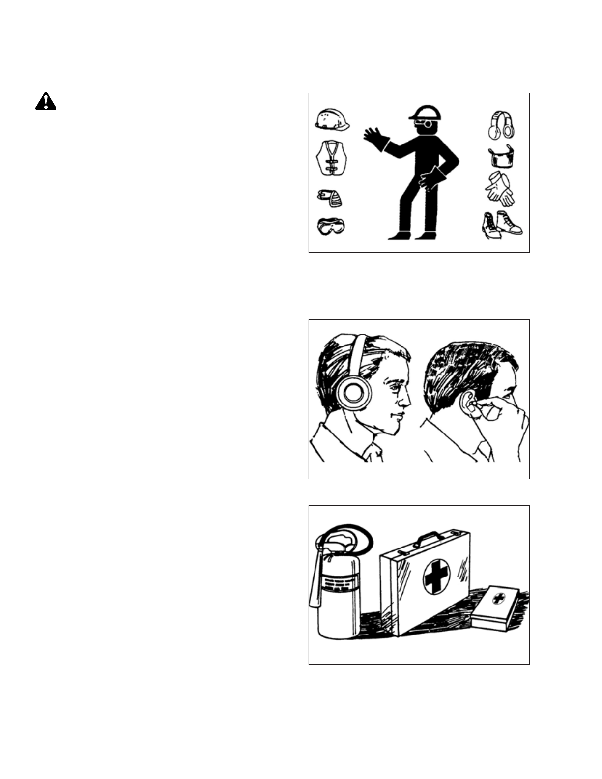
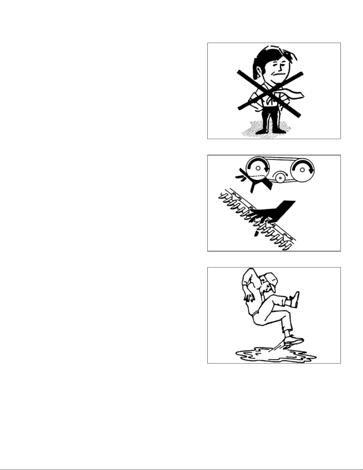
1.2 General Safety .......................................................................................................................................2
1.3 Welding Precaution ................................................................................................................................4
1.4 Safety Signs ...........................................................................................................................................5
Chapter 2: Unloading the Header .............................................................................................................. 7
Chapter 3: Assembling the Header ............................................................................................................ 9
3.1 Removing Shipping Supports ....................................................................................................................9
3.1.1 Installing Adjustable Gauge Roller Kit............................................................................................... 12
3.1.2 Installing Adjustable Skid Shoes Kit.................................................................................................. 15
3.2 Lowering the Header............................................................................................................................. 18
3.3 Unpacking Hydraulic Hoses and Electrical Harness...................................................................................... 20
3.4 Removing Shipping Stands ..................................................................................................................... 21
3.5 Adjusting Rear Baffle Deflectors .............................................................................................................. 23
3.6 Unpacking Curtain ................................................................................................................................ 25
Chapter 4: Attaching Header to M1240 Windrower............................................................................... 27
4.1 Assembling and Installing Forming Shield.................................................................................................. 27
4.2 Routing Electrical Harness ...................................................................................................................... 35
4.3 Attaching Disc Header ........................................................................................................................... 38
4.4 Connecting Rotary Disc Header Hydraulics Using Quick Couplers .................................................................. 45
4.5 Connecting Disc Header Hydraulics Using Hard Plumbing ............................................................................ 47
4.6 Restoring Float for Disc Header............................................................................................................... 50
4.7 Calibrating Windrower Knife Drive on the Harvest Performance Tracker Display.............................................. 52
Chapter 5: Installing Options.................................................................................................................... 55
5.1 Electric Remote Baffle Kit....................................................................................................................... 55
5.2 Crop Dividers Kit................................................................................................................................... 56
5.3 Adjustable Gauge Roller Kit .................................................................................................................... 58
5.4 Adjustable Skid Shoes Kit ....................................................................................................................... 59
Chapter 6: Lubricating the Disc Header................................................................................................... 61
6.1 Lubrication Locations ............................................................................................................................ 62
Chapter 7: Performing Predelivery Checks.............................................................................................. 65
7.1 Conditioner Drive Belt ........................................................................................................................... 65
7.1.1 Inspecting Conditioner Drive Belt.................................................................................................... 65
7.1.2 Adjusting Conditioner Drive Belt ..................................................................................................... 66
TABLE OF CONTENTS

214882 iv Revision C
7.2 Header Float........................................................................................................................................ 68
7.2.1 Checking Float............................................................................................................................. 68
7.2.2 Setting the Float .......................................................................................................................... 69
7.3 Roll Timing .......................................................................................................................................... 70
7.3.1 Adjusting Roll Timing .................................................................................................................... 70
7.4 Roll Gap.............................................................................................................................................. 74
7.4.1 Adjusting Roll Gap........................................................................................................................ 74
7.5 Roll Tension......................................................................................................................................... 75
7.5.1 Checking Roll Tension ................................................................................................................... 75
7.5.2 Adjusting Roll Tension................................................................................................................... 76
7.6 Hanging Drums .................................................................................................................................... 77
7.6.1 Checking and Adjusting Hanging Drum Drive..................................................................................... 77
7.7 Feed Roll Drive..................................................................................................................................... 78
7.7.1 Checking and Adjusting Feed Roll Drive............................................................................................ 78
7.8 Checking and Adding Conditioner Roll Timing Gearbox Oil ........................................................................... 79
7.9 Checking and Adding Oil in Header Drive Gearbox...................................................................................... 80
7.10 Checking and Adding Lubricant in Cutterbar ............................................................................................ 82
7.11 Checking Lights................................................................................................................................... 85
7.12 Checking Manuals............................................................................................................................... 86
7.13 Running up the Header ........................................................................................................................ 87
Chapter 8: Reference ................................................................................................................................ 89
8.1 Recommended Lubricants...................................................................................................................... 89
8.2 Torque Specifications ............................................................................................................................ 90
8.2.1 Metric Bolt Specifications .............................................................................................................. 90
8.2.2 Metric Bolt Specifications Bolting into Cast Aluminum ........................................................................ 92
8.2.3 O-Ring Boss Hydraulic Fittings –Adjustable ...................................................................................... 93
8.2.4 O-Ring Boss Hydraulic Fittings –Non-Adjustable................................................................................ 95
8.2.5 O-Ring Face Seal Hydraulic Fittings.................................................................................................. 96
8.2.6 Tapered Pipe Thread Fittings.......................................................................................................... 97
8.3 Conversion Chart.................................................................................................................................. 98
8.4 Definitions .......................................................................................................................................... 99
Predelivery Checklist .............................................................................................................................. 101
TABLE OF CONTENTS

214882 1Revision C
Chapter 1: Safety
1.1 Signal Words
Three signal words, DANGER,WARNING, and CAUTION, are used to alert you to hazardous situations. Two signal words,
IMPORTANT and NOTE, identify non-safety related information. Signal words are selected using the following guidelines:
DANGER
Indicates an imminently hazardous situation that, if not avoided, will result in death or serious injury.
WARNING
Indicates a potentially hazardous situation that, if not avoided, could result in death or serious injury. It may also be
used to alert against unsafe practices.
CAUTION
Indicates a potentially hazardous situation that, if not avoided, may result in minor or moderate injury. It may be used
to alert against unsafe practices.
IMPORTANT:
Indicates a situation that, if not avoided, could result in a malfunction or damage to the machine.
NOTE:
Provides additional information or advice.

214882 2Revision C
1.2 General Safety
1000004
Figure 1.1: Safety Equipment
CAUTION
The following general farm safety precautions should be part of
your operating procedure for all types of machinery.
Protect yourself.
•When assembling, operating, and servicing machinery, wear
all protective clothing and personal safety devices that could
be necessary for job at hand. Do NOT take chances. You may
need the following:
•Hard hat
•Protective footwear with slip-resistant soles
•Protective glasses or goggles
•Heavy gloves
•Wet weather gear
•Respirator or filter mask
1000005
Figure 1.2: Safety Equipment
•Be aware that exposure to loud noises can cause hearing
impairment or loss. Wear suitable hearing protection devices
such as earmuffs or earplugs to help protect against loud
noises.
1010391
Figure 1.3: Safety Equipment
•Provide a first aid kit in case of emergencies.
•Keep a properly maintained fire extinguisher on the machine.
Be familiar with its proper use.
•Keep young children away from machinery at all times.
•Be aware that accidents often happen when the operator is
tired or in a hurry. Take time to consider safest way. NEVER
ignore warning signs of fatigue.
SAFETY

214882 3Revision C
1000007
Figure 1.4: Safety around Equipment
•Wear close-fitting clothing and cover long hair. NEVER wear
dangling items such as scarves or bracelets.
•Keep all shields in place. NEVER alter or remove safety
equipment. Make sure driveline guards can rotate
independently of shaft and can telescope freely.
•Use only service and repair parts made or approved by
equipment manufacturer. Substituted parts may not meet
strength, design, or safety requirements.
1000008
Figure 1.5: Safety around Equipment
•Keep hands, feet, clothing, and hair away from moving parts.
NEVER attempt to clear obstructions or objects from a
machine while engine is running.
•Do NOT modify machine. Unauthorized modifications may
impair machine function and/or safety. It may also shorten
machine’s life.
•To avoid injury or death from unexpected startup of machine,
ALWAYS stop the engine and remove the key from the
ignition before leaving the operator’s seat for any reason.
1000009
Figure 1.6: Safety around Equipment
•Keep service area clean and dry. Wet or oily floors are
slippery. Wet spots can be dangerous when working with
electrical equipment. Be sure all electrical outlets and tools
are properly grounded.
•Keep work area well lit.
•Keep machinery clean. Straw and chaff on a hot engine is a
fire hazard. Do NOT allow oil or grease to accumulate on
service platforms, ladders, or controls. Clean machines before
storage.
•NEVER use gasoline, naphtha, or any volatile material for
cleaning purposes. These materials may be toxic and/or
flammable.
•When storing machinery, cover sharp or extending
components to prevent injury from accidental contact.
SAFETY

214882 4Revision C
1.3 Welding Precaution
Welding should never be attempted on the header while it is connected to a windrower.
WARNING
Severe damage to sensitive, expensive electronics can result from welding on the header while it is connected to the
windrower. It can be impossible to know what effect high current could have with regard to future malfunctions or
shorter lifespan. It is very important that welding on the header is not attempted while the header is connected to the
windrower.
If you need to do any welding on the header, it should first be disconnected and removed from the windrower.
If it is unfeasible to disconnect the header from the windrower before attempting welding,for welding precautions detailing
all electrical components that must be disconnected first for safe welding.
SAFETY

214882 5Revision C
1.4 Safety Signs
1000694
Figure 1.7: Operator’s Manual Decal
•Keep safety signs clean and legible at all times.
•Replace safety signs that are missing or illegible.
•If original part on which a safety sign was installed is
replaced, be sure the repair part displays the current
safety sign.
SAFETY


214882 7Revision C
Chapter 2: Unloading the Header
WARNING
To avoid injury to bystanders from being struck by machinery, do NOT allow people to stand in unloading area.
1013855
A
B
C
Figure 2.1: Minimum Lifting Capacity
A - Load Center of Gravity
B - Load Center 1220 mm (48 in.) from Back of Forks
C - Minimum Fork Length 1981 mm (78 in.)
IMPORTANT:
Equipment used for unloading the header must meet or exceed
the requirements specified below. Using inadequate equipment
may result in chain breakage, machine damage, or the vehicle
tipping.
NOTE:
Forklifts are normally rated for a load located 610 mm (24 in.)
ahead of the back end of the forks. To obtain the forklift
capacity at 1220 mm (48 in.), check with your forklift distributor.
Table 2.1 Lifting Vehicle
Minimum Capacity 3630 kg (8000 lb.)
Minimum Fork Length 198 cm (78 in.)
1028160
Figure 2.2: Lifting Rotary Disc Header off Trailer
1. Remove the hauler’s tie-down straps and chains.
WARNING
Be sure forks are secure before moving away from load. Stand
clear when lifting.
2. Approach the rotary disc header from its underside and
slide the forks under the lifting framework as far as
possible.
IMPORTANT:
If the load is two units wide, take care to avoid contacting
the other machine.
3. Raise the rotary disc header off the deck.

214882 8Revision C
1028097
Figure 2.3: Moving Disc Header with Forklift
4. Back up until the rotary disc header clears the trailer, and
slowly lower it to 150 mm (6 in.) from the ground.
5. Take the rotary disc header to the storage or setup area.
6. Set the rotary disc header down on secure, level ground. Do
NOT lower the header into working position.
7. Check for shipping damage and missing parts.
UNLOADING THE HEADER

214882 9Revision C
Chapter 3: Assembling the Header
Follow each procedure in this chapter in order.
3.1 Removing Shipping Supports
To remove the shipping supports from the cutterbar side of the header, follow these steps:
1027916
A
A
A
A
B
B
B
Figure 3.1: Shipping Supports
1. Remove four bolts and nuts (A) from each yellow shipping
support (B) and remove the four supports from the
disc header.

214882 10 Revision C
1029718
B
B
AA
A
A
A
A
Figure 3.2: Shipping Stand Brace –Right Side Shown,
Left Side Opposite
2. Remove nuts and bolts (A) from the yellow channel and
header supports.
3. Remove yellow braces (B) from the header.
1029724
A
A
A
A
A
B
B
B
Figure 3.3: Shipping Channel –Right Side Shown, Left
Side Opposite
4. Remove four nuts and bolts (A) holding yellow channel (B)
in place against the plates on both sides of the header.
5. Remove channel (B) from the header.
ASSEMBLING THE HEADER

214882 11 Revision C
1029728
AA
A
A
A
B
B
Figure 3.4: Plates
6. Remove three bolts and washers (A) holding each yellow
plate (B) onto the header supports.
7. Remove plates (B) from the header.
8. Each header is shipped with either gauge rollers or skid
shoes (but not both). Refer to the relevant installation
procedure listed below:
•3.1.1 Installing Adjustable Gauge Roller Kit, page 12
•3.1.2 Installing Adjustable Skid Shoes Kit, page 15
ASSEMBLING THE HEADER

214882 12 Revision C
3.1.1 Installing Adjustable Gauge Roller Kit
Follow these steps and install the Adjustable Gauge Roller kit (MD #B6666) while the header is still set on the ground on its
shipping stands:
NOTE:
If you are installing the Adjustable Skid Shoe kit (MD #B6667), refer to 3.1.2 Installing Adjustable Skid Shoes Kit, page 15.
1028056
A
B
B
C
C
Figure 3.5: Gauge Rollers
1. Remove the gauge rollers from the shipping crate and
remove lynch pin (A) and bar (B) from each gauge roller (C).
Retain the bars and lynch pins.
ASSEMBLING THE HEADER

214882 13 Revision C
1028810
A
A
B
B
C
F
D
E
E
F
C
Figure 3.6: Gauge Roller Assembly
2. Remove and retain clevis pins (A) and lynch pins (B) from
holes (C) on both ends of gauge roller (D).
3. Align holes (C) with holes (E) in the header’s support
bracket (F).
1028035
A
B
C
C
D
Figure 3.7: Clevis Pins and Lynch Pins
4. Secure gauge roller (A) to support bracket (B) using
retained clevis pins (C) and lynch pins (D).
NOTE:
Insert clevis pins (C) from outside gauge roller (A) and
secure with lynch pins (D) from inside gauge roller (A).
ASSEMBLING THE HEADER

214882 14 Revision C
1028033
A
B
Figure 3.8: Bar and Support Bracket
5. Fully insert retained bar (A) into slot (B) from the inboard
side of the gauge roller.
1028030
A
B
Figure 3.9: Bar and Lynch Pin
6. Secure bar (A) with retained lynch pin (B).
7. Repeat the installation on the opposite side of the
disc header.
8. Continue to 3.2 Lowering the Header, page 18.
ASSEMBLING THE HEADER
Other manuals for R216
11
Table of contents
Other MacDon Farm Equipment manuals

MacDon
MacDon R116 User manual

MacDon
MacDon M105 User manual

MacDon
MacDon M205 2012 User manual

MacDon
MacDon M100 User manual

MacDon
MacDon A30-D User manual

MacDon
MacDon M150 User manual

MacDon
MacDon M2170NT User manual

MacDon
MacDon D1X Series User manual

MacDon
MacDon M1170NT5 User manual

MacDon
MacDon R216 User manual