MacDon R85 User manual

The harvesting specialists.
R85
Rotary Disc 16-Foot Header for
Self-Propelled Windrower
Operator’s Manual
214014 Revision B
Model Year 2017
Original Instruction

R85 Rotary Disc 16-Foot Self-Propelled Windrower Header
Published: October 2016

Declaration of Conformity
Figure 1: EC Declaration of Conformity, Page 1
214014 iRevision B

Figure 2: EC Declaration of Conformity, Page 2
214014 ii Revision B

Noise Levels
The A-weighted sound pressure level inside the operator’s station of a typical self-propelled vehicle (e.g., M205),
when operated in conjunction with this R85 rotary disc header, is 79 dBA. This measurement was taken in
accordance with ISO 5131. The sound pressure level depends upon the rotary disc speed, crop conditions, as well
theexacttypeofself-propelledvehicleusedtopowertheR85.
214014 iiiRevision B

Introduction
This manual describes operating and maintenance procedures for the MacDon R85 Rotary Disc 16-Foot
Self-Propelled Windrower Header.
Your new 16-foot rotary header can be attached to MacDon M200, M205, and M1240 Self-Propelled Windrowers
and is designed to cut, condition, and lay in windrows a wide variety of grasses and hay crops.
Carefully read all the material provided before attempting to use or service the machine.
Use this manual as your first source of information for the machine.
A parts catalog is also supplied with your new header. If you require more detailed service information, contact your
MacDon Dealer.
When setting up the machine or making adjustments, review and follow the recommended machine settings in all
relevant MacDon publications. Failure to do so may compromise machine function and machine life and may result
in a hazardous situation.
MacDon provides warranty for Customers who operate and maintain their equipment as described in this manual.
A copy of the MacDon Industries Limited Warranty Policy, which explains this warranty, should have been provided
to you by your Dealer. Damage resulting from any of the following conditions will void the warranty:
• Accident
•Misuse
•Abuse
• Improper maintenance or neglect
• Abnormal or extraordinary use of the machine
• Failure to use the machine, equipment, component, or part in accordance with the manufacturer’s instructions
Use the Table of Contents and the Index to guide you to specific areas. Study the Table of Contents to familiarize
yourself with how the material is organized. Keep this manual handy for frequent reference and to pass on to new
Operators or Owners. Call your Dealer if you need assistance, information, or additional copies of this manual.
NOTE: Keep your MacDon publications up-to-date. The most current version can be downloaded from our website
www.macdon.com or from our Dealer-only site (https://portal.macdon.com) (login required).
Store the operator’s manual and the parts catalog in the
plastic manual case (A) located at the right-hand side of
the header.
Figure 3: Manual Storage Case
214014 iv Revision B

Serial Number(s)
Record the serial number of the header in the
space provided.
Header Serial No: ____________
The serial number plate (A) is located on the top cover at
the right side of the header.
Figure 4: Serial Number Location –
Self-Propelled
214014 vRevision B

List of Revisions
At MacDon, we’re continuously making improvements: occasionally these improvements impact product
documentation. The following list provides an account of major changes from the previous version of this document.
Summary of Change Location
Updated fluids and capacities table. 5.2 Recommended Fluids and Lubricants, page 120
Updated conversion chart. 8.2 Conversion Chart, page 198
214014 vi Revision B

TABLE OF CONTENTS
Declaration of Conformity.................................................................................................................. i
Noise Levels ................................................................................................................................... iii
Introduction .....................................................................................................................................iv
Serial Number(s) ............................................................................................................................. v
List of Revisions ..............................................................................................................................vi
1 Safety .................................................................................................................................................... 1
1.1 Safety Alert Symbols........................................................................................................................ 1
1.2 Signal Words................................................................................................................................... 2
1.3 General Safety ................................................................................................................................ 3
1.4 Maintenance Safety ......................................................................................................................... 5
1.5 Hydraulic Safety .............................................................................................................................. 6
1.6 Safety Signs.................................................................................................................................... 7
1.6.1 Installing Safety Decals ............................................................................................................ 7
1.7 Safety Decal Locations .................................................................................................................... 8
1.8 Understanding Safety Signs ............................................................................................................11
2 Product Overview................................................................................................................................19
2.1 Definitions ..................................................................................................................................... 19
2.2 Component Identification................................................................................................................ 21
2.3 Specifications ................................................................................................................................ 22
3 Operation ............................................................................................................................................ 25
3.1 Owner/Operator Responsibilities..................................................................................................... 25
3.2 Operational Safety ......................................................................................................................... 26
3.3 Engaging and Disengaging the Header Safety Props ....................................................................... 28
3.4 Driveshields .................................................................................................................................. 30
3.4.1 Opening the Driveshield: North American Headers................................................................... 30
3.4.2 Closing the Driveshield: North American Headers .................................................................... 30
3.4.3 Opening the Driveshield: Export Headers ................................................................................ 31
3.4.4 Closing the Driveshield: Export Headers.................................................................................. 31
3.4.5 Removing Right Endshield...................................................................................................... 32
3.4.6 Installing Right Endshield........................................................................................................ 32
3.5 Cutterbar Doors............................................................................................................................. 33
3.5.1 Opening the Cutterbar Doors: North America........................................................................... 34
3.5.2 Closing the Cutterbar Doors: North American Header............................................................... 35
3.5.3 Opening the Cutterbar Doors: Export Header........................................................................... 36
3.5.4 Closing the Cutterbar Doors: Export Header ............................................................................ 37
3.6 Daily Start-Up Check ..................................................................................................................... 39
3.7 Attaching the Header ..................................................................................................................... 41
3.7.1 Attaching the Forming Shield ..................................................................................................41
3.7.2 Attaching Header to an M200 and M205 Self-Propelled Windrower ........................................... 44
3.7.3 Attaching Hydraulic Center-Link: M1240 Windrowers ............................................................... 46
3.7.4 Attaching Hydraulic and Electrical Components: M1240 Windrowers......................................... 50
Routing Hydraulic Hoses and Electrical Components to M1240 Windrowers....................... 51
Connecting Header Hydraulics Using Quick Couplers: M1240 Windrowers ........................ 52
Connecting Header Hydraulics Using Hard Plumbing: M1240 Windrowers ......................... 53
3.7.5 Attaching Hydraulic and Electrical Components: M205 Windrowers........................................... 55
3.7.6 Attaching Hydraulic and Electrical Components: M200 Windrowers........................................... 60
3.8 Detaching the Header .................................................................................................................... 67
3.8.1 Detaching the Header: M205 Windrowers................................................................................ 67
3.8.2 Detaching the Header: M200 Windrowers................................................................................ 71
3.8.3 Detaching the Header: M1240 Windrowers.............................................................................. 73
3.9 Break-In Period ............................................................................................................................. 79
3.10 Shutting down the Windrower ......................................................................................................... 80
3.11 Transporting the Header................................................................................................................. 81
214014 viiRevision B

TABLE OF CONTENTS
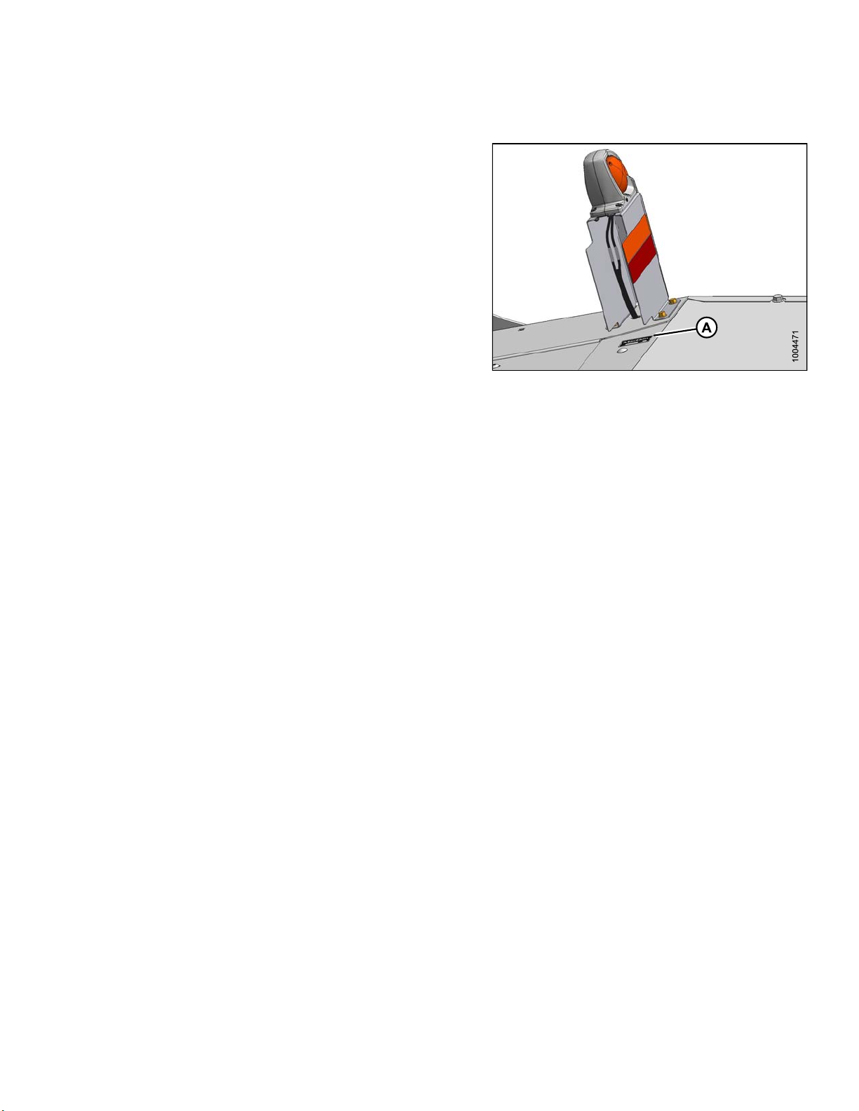
3.12 Adjusting the Transport Lights ........................................................................................................ 82
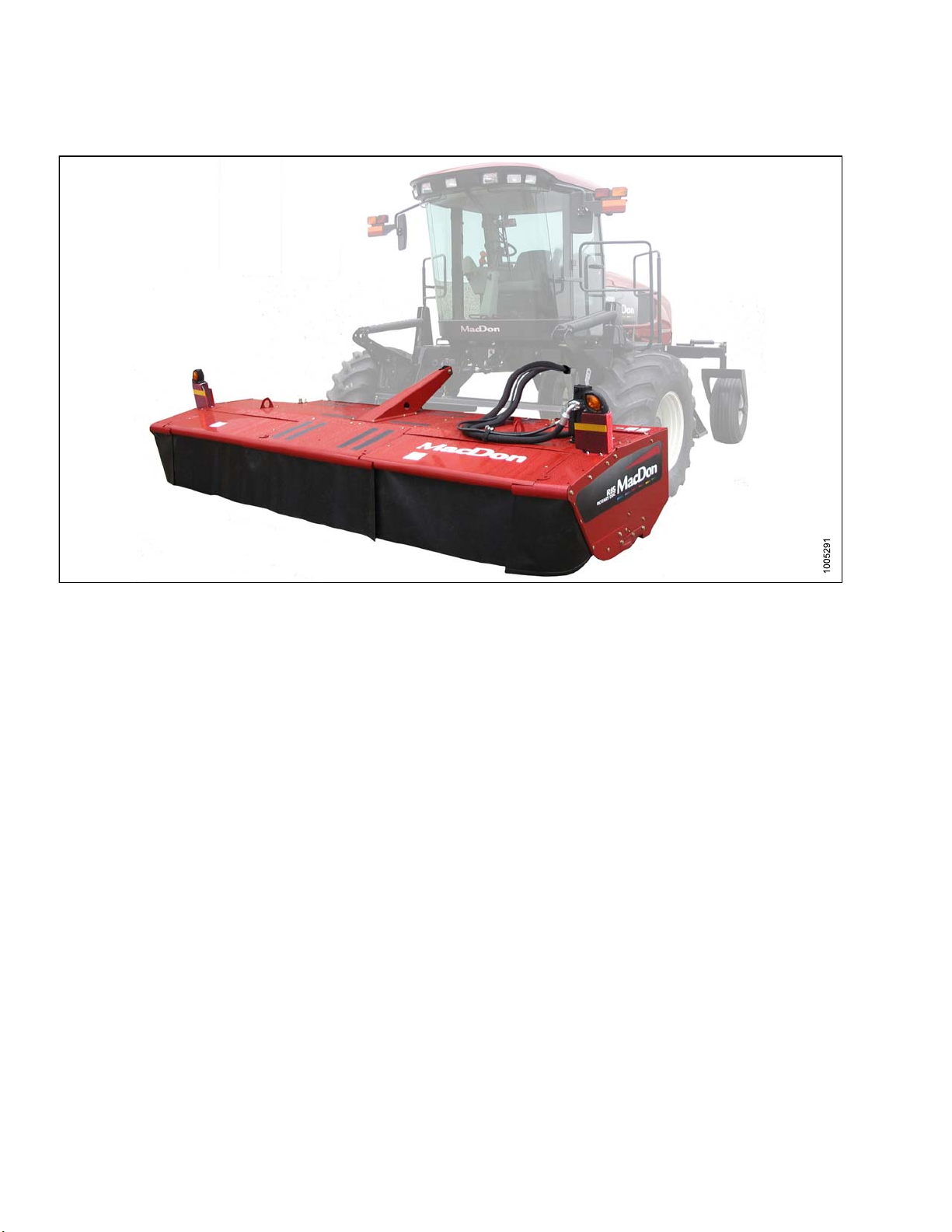
4 Operating the Header .......................................................................................................................... 83
4.1 Header Float ................................................................................................................................. 83
4.1.1 Checking Float....................................................................................................................... 83
4.1.2 Adjusting Float for M200 and M205 Self-Propelled Windrowers................................................. 84
4.1.3 Removing and Restoring Float for M1240 Self-Propelled Windrowers........................................ 84
4.2 Roll Gap........................................................................................................................................ 86
4.2.1 Checking Roll Gap ................................................................................................................. 86
4.2.2 Adjusting Roll Gap ................................................................................................................. 87
4.3 Roll Tension .................................................................................................................................. 89
4.3.1 Adjusting Roll Tension ............................................................................................................ 89
4.4 Roll Timing .................................................................................................................................... 90
4.4.1 Checking Roll Timing.............................................................................................................. 90
4.4.2 Adjusting Roll Timing.............................................................................................................. 91
4.5 Forming Shields ............................................................................................................................ 92
4.5.1 Adjusting the Side Deflectors .................................................................................................. 92
4.5.2 Adjusting the Rear Deflector (Fluffer Shield)............................................................................. 94
4.5.3 Adjusting the Swath Baffle ...................................................................................................... 94
4.6 Header Angle ................................................................................................................................ 96
4.7 Cutting Height ............................................................................................................................... 97
4.7.1 Adjusting Gauge Roller Height ................................................................................................ 97
4.7.2 Adjusting the Skid Shoe Height ............................................................................................... 97
4.8 Disc Speed.................................................................................................................................... 99
4.9 Ground Speed..............................................................................................................................100
4.10 Double Windrowing.......................................................................................................................101
4.11 Tall Crop Feed Plates....................................................................................................................102
4.11.1 Removing the Tall Crop Feed Plates from Storage...................................................................102
Installing Tall Crop Feed Plates under Driven Deflector ....................................................103
Installing Tall Crop Feed Plates under Driveline Deflector .................................................103
4.11.2 Removing Tall Crop Feed Plates ............................................................................................104
Removing Tall Crop Feed Plates from under Driven Deflector ...........................................105
Removing Tall Crop Feed Plates from under Driveline Deflector........................................105
4.11.3 Returning Tall Crop Feed Plates to Storage.............................................................................106
4.12 Tall Crop Divider Option ................................................................................................................107
4.12.1 Installing Tall Crop Divider......................................................................................................107
4.12.2 Removing Tall Crop Divider....................................................................................................108
4.13 Overshot Auger ............................................................................................................................110
4.13.1 Adjusting the Overshot Auger.................................................................................................110
4.14 Stripper Bars ................................................................................................................................113
4.14.1 Adjusting the Stripper Bar ......................................................................................................113
4.15 Haying .........................................................................................................................................116
4.15.1 Curing ..................................................................................................................................116
4.15.2 Topsoil Moisture ....................................................................................................................116
4.15.3 Weather and Topography.......................................................................................................116
4.15.4 Windrow Characteristics ........................................................................................................116
4.15.5 Driving on Windrow ...............................................................................................................117
4.15.6 Raking and Tedding...............................................................................................................117
4.15.7 Using Chemical Drying Agents...............................................................................................117
4.16 Unplugging the Header .................................................................................................................118
5Main
tenance and Servicing ................................................................................................................119
5.1 Preparation for Servicing...............................................................................................................119
5.2 Recommended Fluids and Lubricants ............................................................................................120
5.3 Maintenance Requirements...........................................................................................................121
214014 viii Revision B

TABLE OF CONTENTS
5.3.1 Maintenance Schedule/Record...............................................................................................121
5.3.2 Preseason/Annual Service.....................................................................................................124
5.3.3 End-of-Season Service..........................................................................................................124
5.3.4 Lubrication and Servicing.......................................................................................................125
5.3.5 Greasing Procedure ..............................................................................................................125
5.3.6 Lubrication and Servicing Intervals .........................................................................................126
5.3.7 Lubricating the Cutterbar .......................................................................................................131
Draining the Cutterbar Lubricant .....................................................................................131
Filling the Cutterbar Lubricant .........................................................................................133
5.3.8 Rock Guards.........................................................................................................................135
Inspecting the Rock Guards ...........................................................................................135
5.4 Cutterbar Disc Maintenance ..........................................................................................................136
5.4.1 Direction of Spindle Rotation..................................................................................................136
5.4.2 Inspecting the Cutterbar Discs ...............................................................................................137
5.4.3 Removing a Cutterbar Disc ....................................................................................................137
5.4.4 Installing a Cutterbar Disc ......................................................................................................138
5.4.5 Cutterblades .........................................................................................................................139
Inspecting Cutterblades..................................................................................................139
Inspecting Cutterblade Hardware....................................................................................141
Replacing the Cutterblades ............................................................................................143
5.4.6 Accelerators..........................................................................................................................144
Inspecting Accelerators ..................................................................................................145
Replacing Accelerators ..................................................................................................145
5.4.7 Nut Shield.............................................................................................................................147
Inspecting Nut Shield .....................................................................................................147
Replacing Nut Shield......................................................................................................148
5.4.8 Rotary Deflectors ..................................................................................................................148
Inspecting Rotary Deflectors...........................................................................................148
Removing the Driven Deflector .......................................................................................149
Installing the Driven Deflector .........................................................................................150
Removing the Driveline Deflector....................................................................................150
Installing the Driveline Deflector......................................................................................151
5.4.9 Disc Spindles........................................................................................................................152
Replacing a Spindle Key ................................................................................................152
5.4.10 Cutterbar Doors ....................................................................................................................154
Inspecting Curtains ........................................................................................................154
Inspecting Door Latches: North American Header............................................................154
Inspecting Door Latches: Export Header .........................................................................154
Adjusting Door Latches: Export Header...........................................................................155
Replacing Door Latches: Export Header .........................................................................155
Replacing Door Latch Brackets: Export Header ...............................................................156
5.5 Drive Systems ..............................................................................................................................157
5.5.1 Bevel Gearbox ......................................................................................................................157
Changing the Bevel Gearbox Lubricant ...........................................................................157
5.5.2 Conditioner Drive Belt............................................................................................................158
Inspecting the Conditioner Drive Belt...............................................................................158
Replacing the Conditioner Drive Belt...............................................................................159
5.5.3 Conditioner Gearbox .............................................................................................................161
Changing the Conditioner Gearbox Lubricant ..................................................................161
5.5.4 Header Drive Speed Sensor ..................................................................................................163
Adjusting the Header Drive Speed Sensor.......................................................................163
Replacing the Header Drive Speed Sensor......................................................................164
5.5.5 Auger Drive Belt....................................................................................................................165
Inspecting and Adjusting the Auger Drive Belts................................................................165
214014 ix Revision B

TABLE OF CONTENTS
Replacing the Auger Drive Belts .....................................................................................166
5.5.6 Installing Sealed Bearings......................................................................................................169
5.6 Hydraulics ....................................................................................................................................170
5.6.1 Hydraulic Motor.....................................................................................................................170
Removing the Hydraulic Motor........................................................................................170
Installing the Hydraulic Motor..........................................................................................171
5.6.2 Hydraulic Hoses and Lines ....................................................................................................172
5.7 Electrical System ..........................................................................................................................173
5.7.1 Hazard Lights........................................................................................................................173
Hazard Lights: Replacing Bulbs and Lenses....................................................................173
Hazard Lights: Replacing the Lamp Assembly.................................................................173
Hazard Lights: Replacing the Lamp Bracket ....................................................................174
6 Options and Attachments ..................................................................................................................175
6.1 Options and Attachments: Kits ......................................................................................................175
6.1.1 Adjustable Skid Shoe Kit........................................................................................................175
6.1.2 Cutterbar Repair Tool Kit........................................................................................................175
6.1.3 Double Windrow Attachment (DWA)Double Windrow Attachment - Self Propelled .....................176
6.1.4 Gauge Roller ........................................................................................................................176
6.1.5 Hydraulic Drive: 16-Foot for M200 Self-Propelled....................................................................176
6.1.6 Tall Crop Divider Kit...............................................................................................................176
6.1.7 Tall Crop Feed Plate Kit .........................................................................................................177
7 Troubleshooting .................................................................................................................................179
7.1 Header Performance.....................................................................................................................179
7.2 Mechanical Problems....................................................................................................................182
8 Reference...........................................................................................................................................185
8.1 Torque Specifications....................................................................................................................185
8.1.1 SAE Bolt Torque Specifications ..............................................................................................185
8.1.2 Metric Bolt Specifications.......................................................................................................187
8.1.3 Metric Bolt Specifications Bolting into Cast Aluminum..............................................................190
8.1.4 Flare-Type Hydraulic Fittings..................................................................................................190
8.1.5 O-Ring Boss (ORB) Hydraulic Fittings (Adjustable)..................................................................192
8.1.6 O-Ring Boss (ORB) Hydraulic Fittings (Non-Adjustable) ..........................................................194
8.1.7 O-Ring Face Seal (ORFS) Hydraulic Fittings...........................................................................195
8.1.8 Tapered Pipe Thread Fittings .................................................................................................197
8.2 Conversion Chart..........................................................................................................................198
Index ..................................................................................................................................................199
214014 xRevision B

1Safety
1.1 Safety Alert Symbols
This safety alert symbol indicates important safety
messages in this manual and on safety signs on
the machine.
This symbol means:
•ATTENTION!
•BECOME ALERT!
•YOUR SAFETY IS INVOLVED!
Carefully read and follow the safety message
accompanying this symbol.
Why is safety important to you?
• Accidents disable and kill
• Accidents cost
• Accidents can be avoided
Figure 1.1: Safety Symbol
214014 1Revision B

SAFETY
1.2 Signal Words
Three signal words, DANGER, WARNING,andCAUTION, are used to alert you to hazardous situations. The
appropriate signal word for each situation has been selected using the following guidelines:
DANGER
Indicates an imminently hazardous situation that, if not avoided, will result in death or serious injury.
WARNING
Indicates a potentially hazardous situation that, if not avoided, could result in death or serious injury. It
may also be used to alert against unsafe practices.
CAUTION
Indicates a potentially hazardous situation that, if not avoided, may result in minor or moderate injury. It
may be used to alert against unsafe practices.
214014 2Revision B

SAFETY
1.3 General Safety
CAUTION
The following are general farm safety precautions
that should be part of your operating procedure for
all types of machinery.
Protect yourself.
• When assembling, operating, and servicing machinery,
wear all the protective clothing and personal safety
devices that could be necessary for the job at hand. Do
NOT take chances. You may need the following:
• Hard hat
• Protective footwear with slip resistant soles
• Protective glasses or goggles
• Heavy gloves
• Wet weather gear
• Respirator or filter mask
Figure 1.2: Safety Equipment
• Be aware that exposure to loud noises can cause
hearing impairment or loss. Wear suitable hearing
protection devices such as ear muffs or ear plugs to
help protect against objectionable or loud noises.
Figure 1.3: Safety Equipment
•Provideafirst aid kit for use in case of emergencies.
• Keep a fire extinguisher on the machine. Be sure the
fire extinguisher is properly maintained. Be familiar with
its proper use.
• Keep young children away from the machinery at
all times.
• Be aware that accidents often happen when the
Operator is tired or in a hurry. Take the time to
consider the safest way. Never ignore the warning
signs of fatigue.
Figure 1.4: Safety Equipment
214014 3Revision B

SAFETY
•Wearclose-fitting clothing and cover long hair. Never
wear dangling items such as scarves or bracelets.
• Keep all shields in place. NEVER alter or remove safety
equipment. Make sure driveline guards can rotate
independently of the shaft and can telescope freely.
• Use only service and repair parts made or approved by
the equipment manufacturer. Substituted parts may not
meet strength, design, or safety requirements.
Figure 1.5: Safety around Equipment
• Keep hands, feet, clothing, and hair away from moving
parts. NEVER attempt to clear obstructions or objects
from a machine while the engine is running.
•DoNOT modify the machine. Non-authorized
modifications may impair machine function and/or
safety. It may also shorten the machine’s life.
• To avoid bodily injury or death from unexpected startup
of machine, ALWAYS stop the engine and remove
the key from ignition before leaving operator’s seat for
any reason.
Figure 1.6: Safety around Equipment
• Keep the service area clean and dry. Wet or oily floors
are slippery. Wet spots can be dangerous when working
with electrical equipment. Be sure all electrical outlets
and tools are properly grounded.
• Keep work area well lit.
• Keep machinery clean. Straw and chaff on a hot
engine is a fire hazard. Do NOT allow oil or grease to
accumulate on service platforms, ladders, or controls.
Clean machines before storage.
•NEVER use gasoline, naphtha, or any volatile material
for cleaning purposes. These materials may be toxic
and/or flammable.
• When storing machinery, cover sharp or extending
components to prevent injury from accidental contact.
Figure 1.7: Safety around Equipment
214014 4Revision B

SAFETY
1.4 Maintenance Safety
To ensure your safety while maintaining the machine:
• Review the operator’s manual and all safety items
before operation and/or maintenance of the machine.
• Place all controls in Neutral, stop the engine, set
the park brake, remove the ignition key, and wait for
all moving parts to stop before servicing, adjusting,
and/or repairing.
• Follow good shop practices:
– Keep service areas clean and dry
– Be sure electrical outlets and tools are
properly grounded
– Use adequate lighting for the job at hand Figure 1.8: Safety around Equipment
• Relieve pressure from hydraulic circuits before servicing
and/or disconnecting the machine.
• Make sure all components are tight and that steel lines,
hoses, and couplings are in good condition before
applying pressure to hydraulic systems.
• Keep hands, feet, clothing, and hair away from all
moving and/or rotating parts.
• Clear the area of bystanders, especially children, when
carrying out any maintenance, repairs or, adjustments.
• Install transport lock or place safety stands under the
frame before working under the machine.
• If more than one person is servicing the machine at the
same time, be aware that rotating a driveline or other
mechanically-driven component by hand (for example,
accessing a lube fitting) will cause drive components in
other areas (belts, pulleys, and knives) to move. Stay
clear of driven components at all times.
Figure 1.9: Equipment NOT Safe for Children
•Wearprotectivege
ar when working on the machine.
• Wear heavy gloves when working on knife components.
Figure 1.10: Safety Equipment
214014 5Revision B

SAFETY
1.5 Hydraulic Safety
• Always place all hydraulic controls in Neutral
before dismounting.
• Make sure that all components in the hydraulic system
are kept clean and in good condition.
• Replace any worn, cut, abraded, flattened, or crimped
hoses and steel lines.
•DoNOT attempt any makeshift repairs to the hydraulic
lines, fittings, or hoses by using tapes, clamps, cements,
or welding. The hydraulic system operates under
extremely high pressure. Makeshift repairs will fail
suddenly and create hazardous and unsafe conditions.
Figure 1.11: Testing for Hydraulic Leaks
•Wearprop
er hand and eye protection when searching
for high-pressure hydraulic leaks. Use a piece of
cardboard as a backstop instead of hands to isolate
and identify a leak.
•Ifinjur
ed by a concentrated high-pressure stream of
hydraulic fluid, seek medical attention immediately.
Serious infection or toxic reaction can develop from
hydraulic fluid piercing the skin.
Figure 1.12: Hydraulic Pressure Hazard
• Make sure all components are tight and steel lines,
hoses, and couplings are in good condition before
applying pressure to a hydraulic system.
Figure 1.13: Safety around Equipment
214014 6Revision B

SAFETY
1.6 Safety Signs
• Keep safety signs clean and legible at all times.
• Replace safety signs that are missing or
become illegible.
• If original parts on which a safety sign was installed are
replaced, be sure the repair part also bears the current
safety sign.
• Safety signs are available from your Dealer
Parts Department.
Figure 1.14: Operator’s Manual Decal
1.6.1 Installing Safety Decals
1. Clean and dry installation area.
2. Decide on exact location before you remove decal backing paper.
3. Remove smaller portion of split backing paper.
4. Place sign in position and slowly peel back remaining paper, smoothing sign as it is applied.
5. Prick small air pockets with a pin and smooth out.
214014 7Revision B
Other manuals for R85
10
Table of contents
Other MacDon Farm Equipment manuals

MacDon
MacDon FlexDraper FD1 Series User manual

MacDon
MacDon M105 User manual

MacDon
MacDon M155 User manual

MacDon
MacDon M155 User manual

MacDon
MacDon A40-D User manual

MacDon
MacDon FD75 User manual

MacDon
MacDon FlexDraper FD1 Series User manual

MacDon
MacDon D65 User manual

MacDon
MacDon M155 User manual

MacDon
MacDon R85 User manual

MacDon
MacDon 2000-B User manual

MacDon
MacDon R216 User manual

MacDon
MacDon R85 User manual

MacDon
MacDon M1240 User manual

MacDon
MacDon D65 User manual

MacDon
MacDon A30-S User manual

MacDon
MacDon A30-D User manual

MacDon
MacDon R216 Parts list manual

MacDon
MacDon M1170NT5 User manual

MacDon
MacDon M2170 User manual