MacDon Swath Compressor Guide

Swath Compressor
for M1 Series Windrowers
Setup, Operation, and Parts Manual
215953 Revision A
Original Instruction
The Harvesting Specialists.

Swath Compressor for M1 Series Windrowers
1021731
Published July 2022.
© 2022 MacDon Industries, Ltd.
The information in this publication is based on the information available and in effect at the time of printing. MacDon
Industries, Ltd. makes no representation or warranty of any kind, whether expressed or implied, with respect to the
information in this publication. MacDon Industries, Ltd. reserves the right to make changes at any time without notice.

Introduction
Your Machine
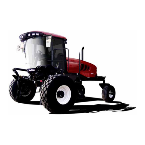
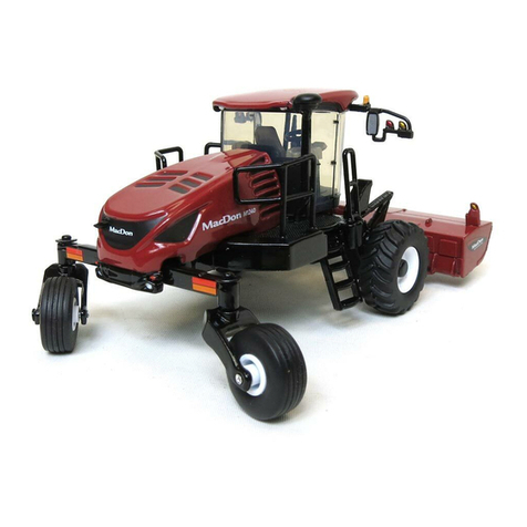
The MacDon Swath Compressor is a large, formed polyethylene sheet designed to mount to the underside of a MacDon
M1 Series Windrower. The MacDon Swath Compressor is designed for use with D1X and D1XL Draper Headers cutting
canola.
IMPORTANT:
M1170NT and M1170NT5 Windrowers are NOT compatible with model year 2022 and prior Swath Compressors. The
model year 2023 Swath Compressor has changes to the dimensions to allow it to be used with a windrower in narrow
transport mode.
The swath compressor shapes the windrow and anchors it into the stubble behind the header to help prevent shelling in
ripe conditions and wind damage. Excessive compression by a swath compressor or roller can increase losses from crop
shelling, and may increase drying time; inadequate compression can leave a windrow prone to wind damage.
The swath compressor height can be adjusted and monitored from within the cab. Height can be adjusted for crop
ripeness, yield, and the amount of compression required. The swath compressor will automatically lift up if an Operator
stops and reverses the windrower.
NOTE:
A preferred height can be saved under a One-Touch-Return preset.
When setting up the machine or making adjustments, review and follow the recommended machine settings in all relevant
MacDon publications. Failure to do so may compromise machine function and machine life and may result in a hazardous
situation.
If the shipment is damaged or is missing parts, contact the following according to your region:
•North America: [email protected]
•Australia: [email protected]
•Brazil: [email protected]
•Europe (except Russia): [email protected]
•Russia: [email protected]
Your Warranty
MacDon provides warranty for Customers who operate and maintain their equipment as described in this manual. A copy
of the MacDon Industries Limited Warranty Policy, which explains this warranty, should have been provided to you by your
Dealer. Damage resulting from any of the following conditions will void the warranty:
•Accident
•Misuse
•Abuse
•Improper maintenance or neglect
•Abnormal or extraordinary use of the machine
•Failure to use the machine, equipment, component, or part in accordance with the manufacturer’s instructions
Your Manual
The following conventions are used in this document:
•M1 Series Windrowers are Dual Direction®, meaning the windrower can be driven in cab-forward or engine-forward
modes. When referencing specific locations on the machine, this manual always assumes a cab-forward direction when
using the terms right and left.
215953 iRevision A

•Unless otherwise noted, use the standard torque values provided in Chapter 6 Reference, page 67 of this document.
NOTE:
Keep your MacDon publications up-to-date. The most current version can be downloaded from our website
(www.macdon.com) or from our Dealer-only site (https://portal.macdon.com) (login required).
Call your MacDon Dealer if you need assistance, information, or additional copies of this manual.
This manual is currently available in English only.
215953 ii Revision A

Summary of Changes
At MacDon, we’re continuously making improvements; occasionally these improvements affect product documentation.
The following list provides an account of major changes from the previous version of this document.
Section Summary of Change Internal Use
Only
Introduction, page i
Added note that M1170NT and M1170NT5 windrowers
are not compatible with 2022 and prior swath
compressors.
Support
Added contact information for shipments with damaged
or missing parts. Publications
1.8 Understanding Safety Signs, page 13
Updated descriptions of safety decals MD #184372 and
MD #166466 to be consistent with other MacDon
manuals. Added missing information to the descriptions
of safety decals MD #174683 and MD #291638.
Publications,
Safety
2.1 Removing Swath Compressor from
Shipping Crate, page 17
Updated shipping assembly to show the new front
deflector MD #310620. ECN 61029
2.2.4 Installing Shield Assembly, page 28 Updated illustration of the front deflector. ECN 60665
Updated illustration of the side deflector in working
position. ECN 62272
Added note that if an M1170NT/NT5 windrower is in
narrow transport mode, there is risk of the side deflectors
contacting the stairs if the deflectors are positioned fully
outboard.
Support
3.2 Calibrating Position Sensor, page 36
Added note that to calibrate the position sensor, the
swath compressor must be attached to the windrower,
but it can be calibrated with or without a header
attached.
Support
3.3.5 Adjusting Side Deflectors, page 44 Updated illustration of the side deflector adjustment. ECN 62272
Added note that if an M1170NT/NT5 windrower is in
narrow transport mode, there is risk of the side deflectors
contacting the stairs if the deflectors are positioned fully
outboard.
Support
4.2.2 Swath Compressor Harness
(MD #209256), page 48 Added cap for P560A to the harness illustration. ECN 55935
5.1 Abbreviations, page 56 Added topic. Publications
5.2 Serial Number Breaks, page 57 Added topic. Publications
5.3 Swath Compressor Shield Assembly,
page 58
Superseded deflector support weldment MD #306165
with MD #306660. Superseded side deflectors
MD #277410 and MD #277411 with MD #306661 and
MD #306662. Updated illustration.
ECN 62272
5.4 Swath Compressor Hydraulics and
Supports, page 60
Superseded front deflector MD #128699 with
MD #310620. Updated illustration. ECN 60665
Removed hydraulic hose MD #277044, and increased the
quantity of hydraulic hose MD #277041 from 1 to 2. ECN 61459
215953 iii Revision A

Serial Number
Record the swath compressor serial number in the space below.
Serial Number: ________________________
1026971
A
Serial Number Plate Location
The serial number plate (A) is located on the left side of the
swath compressor frame.
215953 iv Revision A

215953 vRevision A
Introduction ................................................................................................................................................i
Summary of Changes................................................................................................................................... iii
Serial Number............................................................................................................................................ iv
Chapter 1: Safety ........................................................................................................................................ 1
1.1 Safety Alert Symbols ...............................................................................................................................1
1.2 Signal Words .........................................................................................................................................2
1.3 General Safety .......................................................................................................................................3
1.4 Maintenance Safety ................................................................................................................................5
1.5 Hydraulic Safety .....................................................................................................................................6
1.6 Welding Precaution ................................................................................................................................7
1.7 Safety Signs ......................................................................................................................................... 12
1.7.1 Installing Safety Decals.................................................................................................................. 12
1.8 Understanding Safety Signs .................................................................................................................... 13
Chapter 2: Installation Instructions ......................................................................................................... 17
2.1 Removing Swath Compressor from Shipping Crate ..................................................................................... 17
2.2 Installing Swath Compressor................................................................................................................... 20
2.2.1 Installing Frame ........................................................................................................................... 20
2.2.2 Installing Electrical Harness............................................................................................................ 25
2.2.3 Connecting Hydraulics .................................................................................................................. 26
2.2.4 Installing Shield Assembly.............................................................................................................. 28
Chapter 3: Operation................................................................................................................................ 33
3.1 Activating the Swath Compressor ............................................................................................................ 33
3.2 Calibrating Position Sensor..................................................................................................................... 36
3.3 Using Swath Compressor ....................................................................................................................... 40
3.3.1 Swath Compressor Controls ........................................................................................................... 40
3.3.2 Setting up Swath Compressor......................................................................................................... 41
3.3.3 Programming One-Touch-Return .................................................................................................... 43
3.3.4 Adjusting Compression ................................................................................................................. 43
3.3.5 Adjusting Side Deflectors............................................................................................................... 44
3.3.6 Locking and Unlocking Swath Compressor ........................................................................................ 44
Chapter 4: Maintenance........................................................................................................................... 45
4.1 Removing Swath Compressor Shield ........................................................................................................ 45
4.2 Electrical System .................................................................................................................................. 47
4.2.1 Rotary Sensor (MD #128994) ......................................................................................................... 47
4.2.2 Swath Compressor Harness (MD #209256) ....................................................................................... 48
Harness Connections................................................................................................................... 49
4.2.3 Electrical Schematic...................................................................................................................... 50
4.3 Hydraulic Schematic.............................................................................................................................. 51
TABLE OF CONTENTS


215953 vi Revision A
Chapter 5: Illustrated Parts Lists .............................................................................................................. 55
5.1 Abbreviations ...................................................................................................................................... 56
5.2 Serial Number Breaks............................................................................................................................ 57
5.3 Swath Compressor Shield Assembly ......................................................................................................... 58
5.4 Swath Compressor Hydraulics and Supports.............................................................................................. 60
5.5 Decals ................................................................................................................................................ 64
Chapter 6: Reference ................................................................................................................................ 67
6.1 Torque Specifications ............................................................................................................................ 67
6.1.1 Metric Bolt Specifications .............................................................................................................. 67
6.1.2 Metric Bolt Specifications –Cast Aluminum ...................................................................................... 69
6.1.3 O-Ring Boss Hydraulic Fittings –Adjustable ...................................................................................... 70
6.1.4 O-Ring Boss Hydraulic Fittings –Non-Adjustable................................................................................ 71
6.1.5 O-Ring Face Seal Hydraulic Fittings.................................................................................................. 72
6.1.6 Tapered Pipe Thread Fittings.......................................................................................................... 73
6.2 Conversion Chart.................................................................................................................................. 75
Index.......................................................................................................................................................... 77
Predelivery Checklist ................................................................................................................................ 79
TABLE OF CONTENTS

215953 1Revision A
Chapter 1: Safety
Understanding and consistently following safety procedures helps to ensure the safety of machine operators and
bystanders.
1.1 Safety Alert Symbols
The safety alert symbol indicates important safety messages in this manual and on safety signs on the machine.
1000915
Figure 1.1: Safety Symbol
This symbol means:
•ATTENTION!
•BECOME ALERT!
•YOUR SAFETY IS INVOLVED!
Carefully read and follow the safety message accompanying this
symbol.
Why is safety important to you?
•Accidents disable and kill
•Accidents cost
•Accidents can be avoided

215953 2Revision A
1.2 Signal Words
Three signal words, DANGER,WARNING, and CAUTION, are used to alert you to hazardous situations. Two signal words,
IMPORTANT and NOTE, identify non-safety related information.
Signal words are selected using the following guidelines:
DANGER
Indicates an imminently hazardous situation that, if not avoided, will result in death or serious injury.
WARNING
Indicates a potentially hazardous situation that, if not avoided, could result in death or serious injury. It may also be
used to alert against unsafe practices.
CAUTION
Indicates a potentially hazardous situation that, if not avoided, may result in minor or moderate injury. It may be used
to alert against unsafe practices.
IMPORTANT:
Indicates a situation that, if not avoided, could result in a malfunction or damage to the machine.
NOTE:
Provides additional information or advice.
SAFETY

215953 3Revision A
1.3 General Safety
Protect yourself when assembling, operating, and servicing machinery.
1000004
Figure 1.2: Safety Equipment
CAUTION
The following general farm safety precautions should be part of
your operating procedure for all types of machinery.
Wear all protective clothing and personal safety devices that
could be necessary for the job at hand. Do NOT take chances.
You may need the following:
•Hard hat
•Protective footwear with slip-resistant soles
•Protective glasses or goggles
•Heavy gloves
•Wet weather gear
•Respirator or filter mask
1000005
Figure 1.3: Safety Equipment
In addition, take the following precautions:
•Be aware that exposure to loud noises can cause hearing
impairment. Wear suitable hearing protection devices such
as earmuffs or earplugs to help protect against loud noises.
1010391
Figure 1.4: Safety Equipment
•Provide a first aid kit in case of emergencies.
•Keep a properly maintained fire extinguisher on the
machine. Familiarize yourself with its use.
•Keep young children away from machinery at all times.
•Be aware that accidents often happen when Operators are
fatigued or in a hurry. Take time to consider the safest way
to accomplish a task. NEVER ignore the signs of fatigue.
SAFETY

215953 4Revision A
1000007
Figure 1.5: Safety around Equipment
•Wear close-fitting clothing and cover long hair. NEVER wear
dangling items such as hoodies, scarves or bracelets.
•Keep all shields in place. NEVER alter or remove safety
equipment. Ensure that the driveline guards can rotate
independently of their shaft, and that they can telescope
freely.
•Use only service and repair parts made or approved by the
equipment manufacturer. Parts from other manufacturers
may not meet the correct strength, design, or safety
requirements.
1000008
Figure 1.6: Safety around Equipment
•Keep hands, feet, clothing, and hair away from moving
parts. NEVER attempt to clear obstructions or objects from a
machine while the engine is running.
•Do NOT modify the machine. Unauthorized modifications
may impair the functionality and/or safety of the machine. It
may also shorten the machine’s service life.
•To avoid injury or death from the unexpected startup of the
machine, ALWAYS stop the engine and remove the key from
the ignition before leaving the operator’s seat for any
reason.
1000009
Figure 1.7: Safety around Equipment
•Keep the machine service area clean and dry. Wet and/or
oily floors are slippery. Wet spots can be dangerous when
working with electrical equipment. Ensure that all electrical
outlets and tools are properly grounded.
•Keep the work area well-lit.
•Keep machinery clean. Straw and chaff on a hot engine are
fire hazards. Do NOT allow oil or grease to accumulate on
service platforms, ladders, or controls. Clean machines
before they are stored.
•NEVER use gasoline, naphtha, or any volatile material for
cleaning purposes. These materials may be toxic and/or
flammable.
•When storing machinery, cover any sharp or extending
components to prevent injury from accidental contact.
SAFETY

215953 5Revision A
1.4 Maintenance Safety
Protect yourself when maintaining machinery.
1000009
Figure 1.8: Safety around Equipment
To ensure your safety while maintaining the machine:
•Review the operator’s manual and all safety items before
operating or performing maintenance on the machine.
•Place all controls in Neutral, stop the engine, set the parking
brake, remove the ignition key, and wait for all moving parts
to stop before servicing, adjusting, or repairing the machine.
•Follow good shop practices:
–Keep service areas clean and dry
–Ensure that electrical outlets and tools are properly
grounded
–Keep the work area well lit
1008958
Figure 1.9: Equipment is NOT Safe for Children
•Relieve pressure from hydraulic circuits before servicing
and/or disconnecting the machine.
•Ensure that all components are tight and that steel lines,
hoses, and couplings are in good condition before applying
pressure to hydraulic systems.
•Keep hands, feet, clothing, and hair away from all moving
and/or rotating parts.
•Clear the area of bystanders, especially children, when
carrying out any maintenance, repairs, or adjustments.
•Install the transport lock or place safety stands under the
frame before working under the machine.
•If more than one person is servicing the machine at the
same time, be aware that rotating a driveline or another
mechanically driven component by hand (for example,
accessing a lubricant fitting) will cause drive components in
other areas (belts, pulleys, and knives) to move. Stay clear of
driven components at all times.
1000004
Figure 1.10: Safety Equipment
•Wear protective gear when working on the machine.
•Wear heavy gloves when working on knife components.
SAFETY

215953 6Revision A
1.5 Hydraulic Safety
Protect yourself when assembling, operating, and servicing hydraulic components.
1001205
Figure 1.11: Testing for Hydraulic Leaks
•Always place all hydraulic controls in Neutral before leaving
the operator’s seat.
•Ensure that all the components in the hydraulic system are
kept clean and in good condition.
•Replace any worn, cut, abraded, flattened, or crimped hoses
and steel lines.
•Do NOT attempt any makeshift repairs to hydraulic lines,
fittings, or hoses by using tapes, clamps, cements, or
welding. The hydraulic system operates under extremely
high pressure. Makeshift repairs can fail suddenly and create
hazardous conditions.
1001207
Figure 1.12: Hydraulic Pressure Hazard
•Wear proper hand and eye protection when searching for
high-pressure hydraulic fluid leaks. Use a piece of cardboard
as a backstop instead of your hands to isolate and identify
a leak.
•If injured by a concentrated, high-pressure stream of
hydraulic fluid, seek medical attention immediately. Serious
infection or toxic reaction can develop from hydraulic fluid
piercing the skin.
1000013
Figure 1.13: Safety around Equipment
•Ensure that all components are tight and that steel lines,
hoses, and couplings are in good condition before applying
pressure to a hydraulic system.
SAFETY

215953 7Revision A
1.6 Welding Precaution
Welding should never be attempted on the attachment while it is connected to a windrower.
WARNING
Severe damage to sensitive, expensive electronics can result from welding on the attachment while it is connected to
the windrower. It is impossible to know what effect high current could have with regard to future malfunctions or
shorter lifespan. It is very important that welding to the attachment frame is not attempted while connected to the
windrower.
If welding is required on the attachment frame, it should be removed from the windrower.
If the attachment can not be removed from the windrower, refer to the following for welding precautions detailing
electrical components that must be disconnected before welding.
The following items need to be disconnected:
10176211017621
A
Figure 1.14: Negative Terminals
•Negative battery terminals (A) (two connections)
IMPORTANT:
Always disconnect the battery terminals first, and reconnect
them last.
1017622
A
Figure 1.15: Master Controller
•Master controller (A)
Four connectors: P231, P232, P233, and P234
Location: Behind the cab, near the header lift/fan manifold
To disconnect the connectors, press the two outer tabs, and
pull the connector away from the master controller.
IMPORTANT:
When reconnecting these connectors, ensure that the
connectors are fully seated into the master controller, and
that the two locking tabs on each end of all four connectors
have popped outward. If the tabs are not popped outward,
the connector is not fully seated.
IMPORTANT:
Do NOT power up or operate the windrower until these
connectors are locked into place.
SAFETY

215953 8Revision A
1017623
A
Figure 1.16: Firewall Extension Module
•Firewall extension module (A)
Two connectors: P235 and P236
Location: Behind the cab, near the header lift/fan manifold
To disconnect the connectors, insert the end of a a small
3–6 mm (1/8–1/4 in.) blade screwdriver into the connector’s
locking tab. Gently pry upward (no more than 6 mm
[1/4 in.]) to unlock the connector tab, and then pull the
connector away from the module.
1017624
A
Figure 1.17: Chassis Extension Module
•Chassis extension module (A)
Two connectors: P247 and P248
Location: Under the cab, inside the left frame rail
To disconnect the connectors, insert the end of a small
3–6 mm (1/8–1/4 in.) blade screwdriver into the connector’s
locking tab. Gently pry upward (no more than 6 mm
[1/4 in.]) to unlock the connector tab, and then pull the
connector away from the module.
1019753
A
B
C
C
Figure 1.18: Engine Control Module
•Engine Control Module (ECM)
Two connectors for Cummins: P100 (A) and J1 Cummins
Proprietary ECM Connector (B)
Location: On the engine
To disconnect the connectors, pull the rubber boot off of
the cover, unlock the latch, and undo the main over-center
latch. Remove strain relief bolts (C) so that the connectors
can be pulled away from the ECM.
IMPORTANT:
Be sure to disconnect both connectors. Note the connector
locations for reinstallation.
IMPORTANT:
Be sure to reconnect the connectors in the proper locations.
Do NOT cross connect the connectors.
SAFETY

215953 9Revision A
1017626
A
Figure 1.19: Cab Connectors
NOTE:
To disconnect the remaining circular Deutsch connectors, rotate
the outer collar counterclockwise.
•Cab connectors (A)
Two round connectors: C1 and C2
Location: Under the cab
1017627
A
Figure 1.20: Roof Connectors
•Roof connectors (A)
Four connectors: C10, C12, C13, and C14
Location: Under the cab at the base of the left cab post
1017628
A
Figure 1.21: Chassis Relay Module
•Chassis relay module (A)
Three connectors: P240, P241, and P242
Location: Outside the left frame rail near the batteries
SAFETY

215953 10 Revision A
1017657
A
Figure 1.22: Engine Harness
•Engine harness (A)
Two round connectors: C30 and C31
Location: Inside the left frame rail, at the rear of the
windrower
1017630
A
Figure 1.23: A/C Box Connectors
•Air conditioning (A/C) box connectors (A)
Two connectors: C15 and C16
Location: Rear of the A/C box
1017631
A
Figure 1.24: Wheel Motor Connectors
•Wheel motor connectors (A)
Two round connectors: C25 and C26
Location: Under the center of the frame, just behind the
front cross member
IMPORTANT:
To connect the circular Deutsch connectors without bending
the pins, fully align the plug with the receptacle before
pressing the connector in.
IMPORTANT:
To connect the circular Deutsch connectors without bending the pins, fully align the plug with the receptacle before
pressing the connector in.
SAFETY

215953 11 Revision A
To align the connectors:
1. Observe the channel cuts and mating channel protrusions on the inner part of the circular walls of the connectors.
2. Face the mating connectors towards each other, and rotate the connectors so that the channels are aligned.
3. Press the connectors together while turning the outer connector clockwise until the collar locks.
SAFETY

215953 12 Revision A
1.7 Safety Signs
Safety signs are decals placed on the machine where there is a risk of personal injury, or where the Operator should take
extra precautions before operating the controls. They are usually yellow.
1000694
Figure 1.25: Operator’s Manual Decal
•Keep safety signs clean and legible at all times.
•Replace safety signs that are missing or illegible.
•If the original part on which a safety sign was installed is
replaced, ensure that the repair part displays the current
safety sign.
•Replacement safety signs are available from your MacDon
Dealer.
1.7.1 Installing Safety Decals
Replace any safety decals that are worn or damaged.
1. Decide exactly where you are going to place the decal.
2. Clean and dry the installation area.
3. Remove the smaller portion of the split backing paper.
4. Place the decal in position and slowly peel back the remaining paper, smoothing the decal as it is applied.
5. Prick small air pockets with a pin and smooth them out.
SAFETY
Other manuals for Swath Compressor
1
Table of contents
Other MacDon Farm Equipment manuals

MacDon
MacDon R113 User manual

MacDon
MacDon FD75 User manual

MacDon
MacDon D65 User manual

MacDon
MacDon M1 Series User manual

MacDon
MacDon M1170 Parts list manual

MacDon
MacDon D1X Series User manual

MacDon
MacDon D1X Series User manual

MacDon
MacDon R113 User manual

MacDon
MacDon R80 User manual

MacDon
MacDon R80 User manual

MacDon
MacDon FD75 User manual

MacDon
MacDon R113 User manual

MacDon
MacDon R216 User manual

MacDon
MacDon NEW HOLLAND D2 Series User manual

MacDon
MacDon FlexDraper FD1 Series Parts list manual

MacDon
MacDon DWA Guide

MacDon
MacDon 5000 User manual

MacDon
MacDon R113 User manual

MacDon
MacDon M1 Series User manual

MacDon
MacDon R113 User manual