MacDon R85 User manual

R85
Rotary Disc 16-Foot Header for
Self-Propelled Windrower
Operator’s Manual
214366 Revision A
2018 Model Year
Original Instruction
7KH KDUYHVWLQJ VSHFLDOLVWV

R85 Rotary Disc 4.9-Meter (16-Foot) Self-Propelled Windrower Header
1005291
Published: August 2017

Recommended Fluids and Lubricants
Your machine can operate at top efficiency only if clean lubricants are used.
•Use clean containers to handle all lubricants.
•Store in an area protected from dust, moisture, and other contaminants.
Table .16 Fluids and Capacities
Lubricant Location Description Capacities
Grease
As required
unless otherwise
specified
SAE Multi-Purpose, High temperature extreme
pressure (EP) performance with 0–1% max.
Molybdenum Disulphide (NLGI Grade 2) Lithium
complex base
—
Driveline
slip-joints
High temperature extreme pressure (EP) performance
with 10% max. Molybdenum Disulphide (NLGI
Grade 2) Lithium base
—
Gear Lubricant
Cutterbar
80W-90 gear lubricant with high thermal and oxidation
stability conforming to API gear lubricant service GL-5
minimum (SAE J2360 preferred) specifications such
as Traxon 80W-90 gear oil
4.25L
(4.4USquarts)
Conditioner
gearbox
75W-90 synthetic gear lubricant with high thermal and
oxidation stability conforming to API GL-5 minimum
(SAE J2360 preferred) specifications such as Traxon
E Synthetic 75W-90 gear oil
750ml
(0.79USquarts)
Bevel gearbox 2.1 L (2.2 quarts)

Declaration of Conformity
Figure 1. EC Declaration of Conformity, Page 1
1022972
214366 iRevision A

Figure 2. EC Declaration of Conformity, Page 2
1022973
214366 ii Revision A

Noise Levels
The A-weighted sound pressure level inside the operator’s station of a typical self-propelled vehicle (e.g., M205),
when operated in conjunction with this R85 rotary disc header, is 79 dBA. This measurement was taken in
accordance with ISO 5131. The sound pressure level depends upon the rotary disc speed, crop conditions, as well
the exact type of self-propelled vehicle used to power the R85.
214366 iii Revision A

List of Revisions
At MacDon, we’re continuously making improvements: occasionally these improvements affect product
documentation. The following list provides an account of major changes from the previous version of this
document.
Summary of Change Location
Updated Declaration of Conformity. Declaration of Conformity, page i
Added conventions used in this document. Introduction, page v
Updated illustrations to show new transport lighting
brackets. •Serial Number(s), page vii
•2.2 Component Identification, page 21
Corrected safety decal descriptions for MD #184371,
194465, 194466, and 184386.
1.8 Understanding Safety Signs, page 11
Updated transport light replacement instructions. •Replacing Amber Hazard/Signal Bulb, page 173
•Replacing Amber Hazard/Signal Light Fixture, page
173
Added topic. •4.1.3 Checking Float –M1240 Windrower, page 83
•4.1.4 Setting the Float –M1240 Windrower, page 83
•6.1.8 Solid Drums and Shields Kit, page 178
Removed transport light adjustment procedure; it is not
applicable to the new transport lights.
—
Moved Recommended Fluids and Lubricants to inside
back cover.
Inside back cover
214366 iv Revision A

Introduction
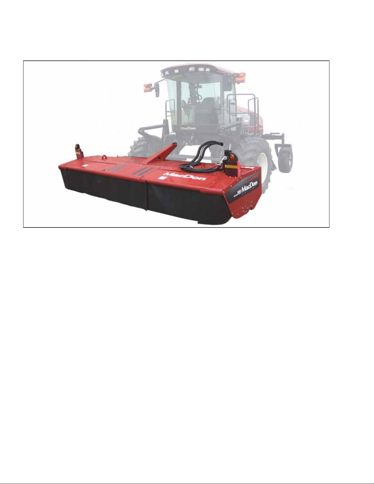
This manual describes operating and maintenance procedures for the MacDon R85 Rotary Disc 16-Foot
Self-Propelled Windrower Header.
Your new 16-foot rotary disc header can be attached to MacDon M200, M205, and M1240 Self-Propelled
Windrowers and is designed to cut, condition, and lay in windrows a wide variety of grasses and hay crops.
Carefully read all the material provided before attempting to use or service the machine.
Use this manual as your first source of information for the machine.
A parts catalog is also supplied with your new header. If you require more detailed service information, contact your
MacDon Dealer.
When setting up the machine or making adjustments, review and follow the recommended machine settings in all
relevant MacDon publications. Failure to do so may compromise machine function and machine life and may result
in a hazardous situation.
MacDon provides warranty for Customers who operate and maintain their equipment as described in this manual. A
copy of the MacDon Industries Limited Warranty Policy, which explains this warranty, should have been provided to
you by your Dealer. Damage resulting from any of the following conditions will void the warranty:
•Accident
•Misuse
•Abuse
•Improper maintenance or neglect
•Abnormal or extraordinary use of the machine
•Failure to use the machine, equipment, component, or part in accordance with the manufacturer’s instructions
Use the Table of Contents and the Index to guide you to specific areas. Study the Table of Contents to familiarize
yourself with how the material is organized. Keep this manual handy for frequent reference and to pass on to new
Operators or Owners. Call your Dealer if you need assistance, information, or additional copies of this manual.
Conventions
The following conventions are used in this document:
•Right and left are determined from the operator’s position, facing forward with the windrower in cab-forward
position.
•Unless otherwise noted, use the standard torque values provided in Chapter 8 Reference, page 185 of this
document.
NOTE: Keep your MacDon publications up-to-date. The most current version can be downloaded from our website
www.macdon.com or from our Dealer-only site (https://portal.macdon.com) (login required).
214366 vRevision A

1004470
A
Figure 3. Manual Storage Case
Store the operator’s manual and the parts catalog in the
plastic manual case (A) located at the right side of the
header.
214366 vi Revision A

Serial Number(s)
1023007
A
Figure 4. Serial Number Location –
Self-Propelled
Record the serial number of the header in the
space provided.
Header Serial No: ____________
The serial number plate (A) is located on the top cover at
the right side of the header.
214366 vii Revision A


214366 ix Revision A
Declaration of Conformity............................................................................................................................i
Noise Levels ............................................................................................................................................ iii
List of Revisions ....................................................................................................................................... iv
Introduction...............................................................................................................................................v
Serial Number(s) ..................................................................................................................................... vii
Chapter 1: Safety .................................................................................................................................... 1
1.1 Safety Alert Symbols ............................................................................................................................1
1.2 Signal Words .......................................................................................................................................2
1.3 General Safety.....................................................................................................................................3
1.4 Maintenance Safety .............................................................................................................................5
1.5 Hydraulic Safety...................................................................................................................................6
1.6 Safety Signs ........................................................................................................................................7
1.6.1 Installing Safety Decals ...............................................................................................................7
1.7 Safety Decal Locations.........................................................................................................................8
1.8 Understanding Safety Signs................................................................................................................ 11
Chapter 2: Product Overview ............................................................................................................ 19
2.1 Definitions .........................................................................................................................................19
2.2 Component Identification ....................................................................................................................21
2.3 Specifications ....................................................................................................................................22
Chapter 3: Operation ........................................................................................................................... 25
3.1 Owner/Operator Responsibilities.........................................................................................................25
3.2 Operational Safety .............................................................................................................................26
3.3 Engaging and Disengaging Header Safety Props .................................................................................28
3.4 Driveshields.......................................................................................................................................30
3.4.1 Opening the Driveshield: North American Headers ......................................................................30
3.4.2 Closing the Driveshield: North American Headers........................................................................30
3.4.3 Opening the Driveshield: Export Headers....................................................................................31
3.4.4 Closing the Driveshield: Export Headers .....................................................................................31
3.4.5 Removing Right Endshield.........................................................................................................32
3.4.6 Installing Right Endshield...........................................................................................................32
3.5 Cutterbar Doors .................................................................................................................................33
3.5.1 Opening the Cutterbar Doors: North America ..............................................................................34
3.5.2 Closing the Cutterbar Doors: North American Header ..................................................................35
3.5.3 Opening the Cutterbar Doors: Export Header ..............................................................................36
3.5.4 Closing the Cutterbar Doors: Export Header................................................................................37
3.6 Daily Start-Up Check..........................................................................................................................39
3.7 Attaching the Header..........................................................................................................................41
3.7.1 Attaching the Forming Shield .....................................................................................................41
TABLE OF CONTENTS

214366 xRevision A
3.7.2 Attaching Header to an M200 and M205 Self-Propelled Windrower...............................................44
3.7.3 Attaching Hydraulic and Electrical Components: M205 Windrowers ..............................................45
3.7.4 Attaching Hydraulic and Electrical Components: M200 Windrowers ..............................................51
3.7.5 Attaching Hydraulic Center-Link with Optional Self-Alignment: M1240 Windrowers ........................57
3.7.6 Attaching Hydraulic and Electrical Components: M1240 Windrowers ............................................62
Routing Hydraulic Hoses and Electrical Components to M1240 Windrowers .................................63
Connecting Header Hydraulics Using Quick Couplers: M1240 Windrowers ...................................64
Connecting Header Hydraulics Using Hard Plumbing: M1240 Windrowers....................................65
3.8 Detaching the Header ........................................................................................................................68
3.8.1 Detaching the Header: M1240 Windrowers .................................................................................68
3.8.2 Detaching the Header: M205 Windrowers ...................................................................................71
3.8.3 Detaching the Header: M200 Windrowers ...................................................................................75
3.9 Break-In Period..................................................................................................................................78
3.10 Shutting down the Windrower............................................................................................................79
3.11 Transporting the Header ...................................................................................................................80
Chapter 4: Operating the Header...................................................................................................... 81
4.1 Header Float......................................................................................................................................81
4.1.1 Checking Float –M200 and M205 Windrowers ............................................................................81
4.1.2 Adjusting Float –M200 and M205 Windrowers ............................................................................82
4.1.3 Checking Float –M1240 Windrower ...........................................................................................83
4.1.4 Setting the Float –M1240 Windrower .........................................................................................83
4.1.5 Removing and Restoring Float –M1240 Windrowers ...................................................................84
4.2 Roll Gap............................................................................................................................................86
4.2.1 Checking Roll Gap ....................................................................................................................86
4.2.2 Adjusting Roll Gap ....................................................................................................................87
4.3 Roll Tension.......................................................................................................................................89
4.3.1 Adjusting Roll Tension ...............................................................................................................89
4.4 Roll Timing ........................................................................................................................................90
4.4.1 Checking Roll Timing.................................................................................................................90
4.4.2 Adjusting Roll Timing .................................................................................................................91
4.5 Forming Shields.................................................................................................................................93
4.5.1 Adjusting the Side Deflectors .....................................................................................................93
4.5.2 Adjusting the Rear Deflector (Fluffer Shield) ................................................................................95
4.5.3 Adjusting the Swath Baffle .........................................................................................................95
4.6 Header Angle ....................................................................................................................................97
4.7 Cutting Height....................................................................................................................................98
4.7.1 Adjusting Gauge Roller Height ...................................................................................................98
4.7.2 Adjusting the Skid Shoe Height ..................................................................................................99
4.8 Disc Speed...................................................................................................................................... 100
4.9 Ground Speed ................................................................................................................................. 101
4.10 Double Windrowing ........................................................................................................................102
TABLE OF CONTENTS

214366 xi Revision A
4.11 Tall Crop Feed Plates .....................................................................................................................103
4.11.1 Removing the Tall Crop Feed Plates from Storage ...................................................................103
Installing Tall Crop Feed Plates under Driven Deflector..............................................................104
Installing Tall Crop Feed Plates under Driveline Deflector ..........................................................105
4.11.2 Removing Tall Crop Feed Plates.............................................................................................106
Removing Tall Crop Feed Plates from under Driven Deflector ....................................................106
Removing Tall Crop Feed Plates from under Driveline Deflector .................................................107
4.11.3 Returning Tall Crop Feed Plates to Storage .............................................................................107
4.12 Tall Crop Divider Option ..................................................................................................................108
4.12.1 Installing Tall Crop Divider......................................................................................................108
4.12.2 Removing Tall Crop Divider ....................................................................................................109
4.13 Overshot Auger.............................................................................................................................. 111
4.13.1 Adjusting the Overshot Auger................................................................................................. 111
4.14 Stripper Bars .................................................................................................................................114
4.14.1 Adjusting the Stripper Bar ...................................................................................................... 114
4.15 Haying .......................................................................................................................................... 117
4.15.1 Curing ..................................................................................................................................117
4.15.2 Topsoil Moisture .................................................................................................................... 117
4.15.3 Weather and Topography....................................................................................................... 117
4.15.4 Windrow Characteristics ........................................................................................................ 118
4.15.5 Driving on Windrow ............................................................................................................... 118
4.15.6 Raking and Tedding............................................................................................................... 118
4.15.7 Using Chemical Drying Agents ............................................................................................... 118
4.16 Unplugging the Header................................................................................................................... 119
Chapter 5: Maintenance and Servicing .........................................................................................121
5.1 Preparation for Servicing ..................................................................................................................121
5.2 Maintenance Requirements ..............................................................................................................122
5.2.1 Maintenance Schedule/Record ................................................................................................122
5.2.2 Preseason/Annual Service.......................................................................................................125
5.2.3 End-of-Season Service............................................................................................................125
5.2.4 Lubrication and Servicing.........................................................................................................126
5.2.5 Greasing Procedure ................................................................................................................127
5.2.6 Lubrication and Servicing Intervals ...........................................................................................127
5.2.7 Lubricating the Cutterbar .........................................................................................................132
Draining the Cutterbar Lubricant ..............................................................................................132
Filling the Cutterbar Lubricant..................................................................................................134
5.2.8 Rock Guards...........................................................................................................................136
Inspecting the Rock Guards ....................................................................................................136
5.3 Cutterbar Discs................................................................................................................................ 137
5.3.1 Direction of Spindle Rotation ....................................................................................................137
5.3.2 Inspecting the Cutterbar Discs..................................................................................................138
5.3.3 Removing a Cutterbar Disc ......................................................................................................138
5.3.4 Installing a Cutterbar Disc ........................................................................................................139
TABLE OF CONTENTS

214366 xii Revision A
5.3.5 Cutterblades ...........................................................................................................................140
Inspecting Discblades .............................................................................................................141
Inspecting Cutterblade Hardware.............................................................................................142
Replacing the Cutterblades .....................................................................................................144
5.3.6 Accelerators ...........................................................................................................................145
Inspecting Accelerators...........................................................................................................146
Replacing Accelerators ...........................................................................................................147
5.3.7 Nut Shield...............................................................................................................................148
Inspecting Nut Shield ..............................................................................................................148
Replacing Nut Shield ..............................................................................................................149
5.3.8 Rotary Deflectors ....................................................................................................................149
Inspecting Rotary Deflectors....................................................................................................149
Removing the Driven Deflector ................................................................................................150
Installing the Driven Deflector ..................................................................................................151
Removing the Driveline Deflector.............................................................................................151
Installing the Driveline Deflector...............................................................................................152
5.3.9 Disc Spindles..........................................................................................................................153
Replacing a Spindle Key .........................................................................................................153
5.3.10 Cutterbar Doors ....................................................................................................................156
Inspecting Curtains.................................................................................................................156
Inspecting Door Latches: North American Header .....................................................................156
Inspecting Door Latches: Export Header ..................................................................................156
Adjusting Door Latches: Export Header....................................................................................156
Replacing Door Latches: Export Header...................................................................................157
Replacing Door Latch Brackets: Export Header ........................................................................157
5.4 Drive Systems ................................................................................................................................. 158
5.4.1 Bevel Gearbox ........................................................................................................................158
Changing the Bevel Gearbox Lubricant ....................................................................................158
5.4.2 Conditioner Drive Belt..............................................................................................................159
Inspecting the Conditioner Drive Belt........................................................................................159
Replacing the Conditioner Drive Belt ........................................................................................160
5.4.3 Conditioner Gearbox ...............................................................................................................162
Changing the Conditioner Gearbox Lubricant ...........................................................................162
5.4.4 Header Drive Speed Sensor ....................................................................................................164
Adjusting the Header Drive Speed Sensor................................................................................164
Replacing the Header Drive Speed Sensor...............................................................................165
5.4.5 Auger Drive Belt......................................................................................................................166
Inspecting and Adjusting the Auger Drive Belts .........................................................................166
Replacing the Auger Drive Belts ..............................................................................................167
5.4.6 Installing Sealed Bearings........................................................................................................169
5.5 Hydraulics .......................................................................................................................................170
5.5.1 Hydraulic Motor.......................................................................................................................170
Removing the Hydraulic Motor.................................................................................................170
Installing the Hydraulic Motor...................................................................................................171
5.5.2 Hydraulic Hoses and Lines.......................................................................................................172
5.6 Electrical System .............................................................................................................................173
5.6.1 Hazard Lights .........................................................................................................................173
Replacing Amber Hazard/Signal Bulb ......................................................................................173
Replacing Amber Hazard/Signal Light Fixture ...........................................................................173
TABLE OF CONTENTS

214366 xiii Revision A
Chapter 6: Options and Attachments............................................................................................ 175
6.1 Options and Attachments: Kits ..........................................................................................................175
6.1.1 Adjustable Skid Shoe Kit..........................................................................................................175
6.1.2 Cutterbar Repair Tool Kit..........................................................................................................175
6.1.3 Double Windrow Attachment (DWA) .........................................................................................176
6.1.4 Gauge Roller ..........................................................................................................................176
6.1.5 Hydraulic Drive: 16-Foot for M200 Self-Propelled ......................................................................176
6.1.6 Tall Crop Divider Kit .................................................................................................................177
6.1.7 Tall Crop Feed Plate Kit ...........................................................................................................177
6.1.8 Solid Drums and Shields Kit .....................................................................................................178
Chapter 7: Troubleshooting .............................................................................................................179
7.1 Header Performance........................................................................................................................179
7.2 Mechanical Problems .......................................................................................................................182
Chapter 8: Reference .........................................................................................................................185
8.1 Torque Specifications .......................................................................................................................185
8.1.1 SAE Bolt Torque Specifications ................................................................................................185
8.1.2 Metric Bolt Specifications .........................................................................................................187
8.1.3 Metric Bolt Specifications Bolting into Cast Aluminum ................................................................189
8.1.4 Flare-Type Hydraulic Fittings....................................................................................................190
8.1.5 O-Ring Boss (ORB) Hydraulic Fittings (Adjustable) ....................................................................191
8.1.6 O-Ring Boss (ORB) Hydraulic Fittings (Non-Adjustable).............................................................193
8.1.7 O-Ring Face Seal (ORFS) Hydraulic Fittings .............................................................................194
8.1.8 Tapered Pipe Thread Fittings ...................................................................................................195
8.2 Conversion Chart.............................................................................................................................196
Index.......................................................................................................................................................197
Recommended Fluids and Lubricants ............................................................. Inside Back Cover
TABLE OF CONTENTS


214366 1Revision A
1 Safety
1.1 Safety Alert Symbols
1000915
Figure 1.1: Safety Symbol
This safety alert symbol indicates important safety
messages in this manual and on safety signs on
the machine.
This symbol means:
•ATTENTION!
•BECOME ALERT!
•YOUR SAFETY IS INVOLVED!
Carefully read and follow the safety message
accompanying this symbol.
Why is safety important to you?
•Accidents disable and kill
•Accidents cost
•Accidents can be avoided

214366 2Revision A
1.2 Signal Words
Three signal words, DANGER, WARNING, and CAUTION, are used to alert you to hazardous situations.
The appropriate signal word for each situation has been selected using the following guidelines:
DANGER
Indicates an imminently hazardous situation that, if not avoided, will result in death or serious injury.
WARNING
Indicates a potentially hazardous situation that, if not avoided, could result in death or serious injury.
It may also be used to alert against unsafe practices.
CAUTION
Indicates a potentially hazardous situation that, if not avoided, may result in minor or moderate injury.
It may be used to alert against unsafe practices.
SAFETY

214366 3Revision A
1.3 General Safety
1000004
Figure 1.2: Safety Equipment
CAUTION
The following are general farm safety precautions that
should be part of your operating procedure for all types
of machinery.
Protect yourself.
•When assembling, operating, and servicing machinery,
wear all protective clothing and personal safety devices
that could be necessary for job at hand. Do NOT take
chances. You may need the following:
•Hard hat
•Protective footwear with slip resistant soles
•Protective glasses or goggles
•Heavy gloves
•Wet weather gear
•Respirator or filter mask
1000005
Figure 1.3: Safety Equipment
•Be aware that exposure to loud noises can cause hearing
impairment or loss. Wear suitable hearing protection
devices such as earmuffs or earplugs to help protect
against loud noises.
1010391
Figure 1.4: Safety Equipment
•Provide a first aid kit for use in case of emergencies.
•Keep a fire extinguisher on the machine. Be sure fire
extinguisher is properly maintained. Be familiar with its
proper use.
•Keep young children away from machinery at all times.
•Be aware that accidents often happen when Operator is
tired or in a hurry. Take time to consider safest way.
Never ignore warning signs of fatigue.
SAFETY
Other manuals for R85
10
Table of contents
Other MacDon Farm Equipment manuals

MacDon
MacDon 5000 User manual

MacDon
MacDon R113 User manual

MacDon
MacDon R85 User manual

MacDon
MacDon D65 User manual

MacDon
MacDon A30-S User manual

MacDon
MacDon Swath Compressor Guide

MacDon
MacDon CA20 User manual

MacDon
MacDon M155E4 User manual

MacDon
MacDon D65 User manual

MacDon
MacDon FlexDraper FD1 Series User manual
Popular Farm Equipment manuals by other brands

Farmers Friend
Farmers Friend Terrateck AP.FF.0001 Notice Instructions

GrainPro
GrainPro TRANSAFELINER MA4081RAD1219-01 instruction manual

Ritchie
Ritchie EcoFount Series installation instructions

Landoll
Landoll 302D-B Operator's manual

Monosem
Monosem NG Plus 4-2020 manual

Krone
Krone Big Pack 890 operating instructions