FD1 Series / FM100 Quick Card – MD #214567 Revision A
Supplement to FD1 Series Combine Header Operator’s Manual
FD1 Series / FM100 Quick Card – MD #214567 Revision A
Supplement to FD1 Series Combine Header Operator’s Manual
1. Before adjusting the float spring adjustment bolts (A), rotate the spring
locks (B) by loosening bolts (C).
2. To increase float (decrease header weight), turn both adjustment
bolts (A) on the left side clockwise. Repeat adjustment at opposite side.
3. To decrease float (increase header weight), turn left side adjustment
bolts (A) counterclockwise. Repeat at opposite side.
IMPORTANT:
Ensure torque wrench indicator readings are equal on both sides of
float module.
NOTE:
For 12.2 and 13.7 m (40 and 45 ft.) double-knife headers, adjust float
as above, then loosen right side float spring bolts two turns.
NOTE:
If adequate header float cannot be achieved using all the available
adjustments, an optional heavy duty spring is available. See your
MacDon Dealer or refer to the parts catalog for ordering information.
Step 4: Setting Header Float
FD1 Series / FM100 Recommended SettingsFD1 Series Draper Header / FM100 Float Module Quick Card Subject to change without notice
1. Place torque wrench (A) onto float lock (B). Note the change in wrench
orientation when checking float module’s left and right side.
2. Push down on torque wrench (A) to rotate bell crank (C) forward.
3. Continue pushing down on torque wrench until the wrench’s
indicator (D) reaches a maximum reading and begins to decrease. Note
the maximum reading.
4. Repeat above steps for opposite side of float module.
5. Refer to Table 1.1 as a guide for float settings.
• If the reading is high, the header is heavy.
• If the reading is low, the header is light.
Step 3: Checking Header Float
Header Size
m (ft.)
Indicator Reading
Cutting on
the Ground
Cutting off
the Ground
9.1 and 10.6 m
(30 and 35 ft.) 1-1/2 to 2 2 to 2-1/2
12.1 and 13.7 m
(40 and 45 ft.) 2 to 2-1/2 2-1/2 to 3
Table 1.1: Float Settings
Delta Rice
Soybeans
Peas
Lentils
Figure 7: Float Adjustment Bolts – Left Side Shown
Figure 6: Checking Float – Left Side Shown
Figure 5: Checking Float – Right Side Shown
IMPORTANT:
Torque settings in Table 1.1: Float Settings are recommended header
float settings. It may be necessary to set float values outside of these
ranges to suit varying crop and field conditions.
1. Remove wing balance linkage cover on left side of the float module by
removing securing bolt and rotating the cover upwards until the inboard
end can be lifted off.
2. Place wing lock spring handles in the unlocked (lower) position.
3. Place torque wrench (A) on bolt (B).
4. Check that pointer (C) is properly positioned as follows:
a. Use the torque wrench (A) to move the bell crank so that the bell
crank’s lower edge (D) is parallel to the top-link’s lower edge (E).
b. Ensure pointer (C) is lined up with the top-link (E). If necessary,
bend the pointer it aligns with bolt hole (J).
5. Move wing upward with torque wrench (A) until the pointer’s lower
alignment tab (F) lines up with the upper edge of the top-link (E). Refer
to Figure 8. Observe the indicator reading (G) on the torque wrench and
record it.
6. Move the wing downward with torque wrench (A) until the pointer’s
upper alignment tab (H) lines up with the lower edge of the top-link (E).
Refer to Figure 9. Observe the indicator reading (G) on the torque
wrench and record it.
7. Check wing balance on opposite side of header.
• If the difference between the readings is 0.5 or less, the wing is
balanced and adjustment is not required.
• If the difference between the readings is more than 0.5, the wing is
not balanced and adjustment is required.
Step 5: Check Wing Balance
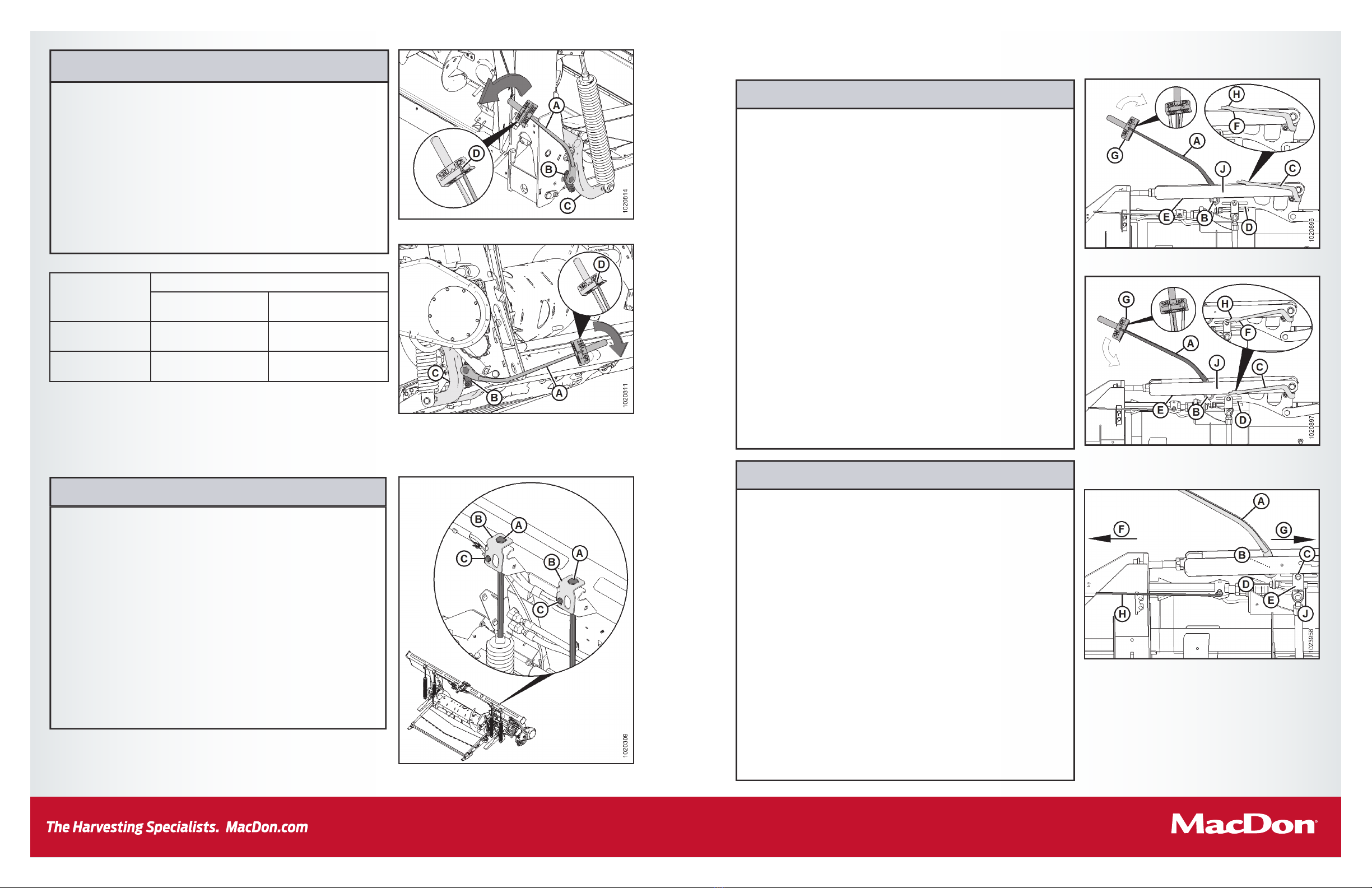
1. Place torque wrench (A) on bolt (B) on the left side of header.
2. Loosen clevis bolt (C) and jam nut (J).
3. Recheck wing balance. Refer to Step 5: Check Wing Balance.
4. If necessary, make the following adjustments:
• If the wing is too heavy, turn the clevis adjuster bolt (D) to move
clevis (E) outboard (F).
• If the wing is too light, turn the clevis adjuster bolt (D) to move
clevis (E) inboard (G).
5. Adjust clevis (E) position (if necessary) until the difference between
torque wrench indicator readings is 0.5 or less. Tighten clevis bolt (C)
and jam nut (J).
6. Place wing lock spring handles (H) in the locked (upper) position. If lock
doesn’t engage, move the wing up and down with the torque wrench (A)
until it locks. When locked, there will be some movement in the linkage.
Repeat on opposite side of header.
7. If the cutterbar is not straight when wings are in lock mode, then further
adjustments are required. Contact your MacDon Dealer.
8. Return the torque wrench (A) to its storage location on the float
module frame.
Step 6: Adjust Wing Balance
IMPORTANT:
Before proceeding, the header float must be set properly. Refer to Step 4: Setting Header Float.
Figure 8: Wing Balance Linkage,
Wings Set too Light – Left Side Shown, Right Opposite
Figure 10: Wing Balance Linkage – Left Side Shown
Figure 9: Wing Balance Linkage,
Wings Set too Heavy – Left Side Shown, Right Opposite
FD1 Series / FM100 Quick Card – MD #214567 Revision A
Supplement to FD1 Series Combine Header Operator’s Manual
FD1 Series / FM100 Quick Card – MD #214567 Revision A
Supplement to FD1 Series Combine Header Operator’s Manual
1. Before adjusting the float spring adjustment bolts (A), rotate the spring
locks (B) by loosening bolts (C).
2. To increase float (decrease header weight), turn both adjustment
bolts (A) on the left side clockwise. Repeat adjustment at opposite side.
3. To decrease float (increase header weight), turn left side adjustment
bolts (A) counterclockwise. Repeat at opposite side.
IMPORTANT:
Ensure torque wrench indicator readings are equal on both sides of
float module.
NOTE:
For 12.2 and 13.7 m (40 and 45 ft.) double-knife headers, adjust float
as above, then loosen right side float spring bolts two turns.
NOTE:
If adequate header float cannot be achieved using all the available
adjustments, an optional heavy duty spring is available. See your
MacDon Dealer or refer to the parts catalog for ordering information.
Step 4: Setting Header Float
FD1 Series / FM100 Recommended SettingsFD1 Series Draper Header / FM100 Float Module Quick Card Subject to change without notice
1. Place torque wrench (A) onto float lock (B). Note the change in wrench
orientation when checking float module’s left and right side.
2. Push down on torque wrench (A) to rotate bell crank (C) forward.
3. Continue pushing down on torque wrench until the wrench’s
indicator (D) reaches a maximum reading and begins to decrease. Note
the maximum reading.
4. Repeat above steps for opposite side of float module.
5. Refer to Table 1.1 as a guide for float settings.
• If the reading is high, the header is heavy.
• If the reading is low, the header is light.
Step 3: Checking Header Float
Header Size
m (ft.)
Indicator Reading
Cutting on
the Ground
Cutting off
the Ground
9.1 and 10.6 m
(30 and 35 ft.) 1-1/2 to 2 2 to 2-1/2
12.1 and 13.7 m
(40 and 45 ft.) 2 to 2-1/2 2-1/2 to 3
Table 1.1: Float Settings
Delta Rice
Soybeans
Peas
Lentils
Figure 7: Float Adjustment Bolts – Left Side Shown
Figure 6: Checking Float – Left Side Shown
Figure 5: Checking Float – Right Side Shown
IMPORTANT:
Torque settings in Table 1.1: Float Settings are recommended header
float settings. It may be necessary to set float values outside of these
ranges to suit varying crop and field conditions.
1. Remove wing balance linkage cover on left side of the float module by
removing securing bolt and rotating the cover upwards until the inboard
end can be lifted off.
2. Place wing lock spring handles in the unlocked (lower) position.
3. Place torque wrench (A) on bolt (B).
4. Check that pointer (C) is properly positioned as follows:
a. Use the torque wrench (A) to move the bell crank so that the bell
crank’s lower edge (D) is parallel to the top-link’s lower edge (E).
b. Ensure pointer (C) is lined up with the top-link (E). If necessary,
bend the pointer it aligns with bolt hole (J).
5. Move wing upward with torque wrench (A) until the pointer’s lower
alignment tab (F) lines up with the upper edge of the top-link (E). Refer
to Figure 8. Observe the indicator reading (G) on the torque wrench and
record it.
6. Move the wing downward with torque wrench (A) until the pointer’s
upper alignment tab (H) lines up with the lower edge of the top-link (E).
Refer to Figure 9. Observe the indicator reading (G) on the torque
wrench and record it.
7. Check wing balance on opposite side of header.
• If the difference between the readings is 0.5 or less, the wing is
balanced and adjustment is not required.
• If the difference between the readings is more than 0.5, the wing is
not balanced and adjustment is required.
Step 5: Check Wing Balance
1. Place torque wrench (A) on bolt (B) on the left side of header.
2. Loosen clevis bolt (C) and jam nut (J).
3. Recheck wing balance. Refer to Step 5: Check Wing Balance.
4. If necessary, make the following adjustments:
• If the wing is too heavy, turn the clevis adjuster bolt (D) to move
clevis (E) outboard (F).
• If the wing is too light, turn the clevis adjuster bolt (D) to move
clevis (E) inboard (G).
5. Adjust clevis (E) position (if necessary) until the difference between
torque wrench indicator readings is 0.5 or less. Tighten clevis bolt (C)
and jam nut (J).
6. Place wing lock spring handles (H) in the locked (upper) position. If lock
doesn’t engage, move the wing up and down with the torque wrench (A)
until it locks. When locked, there will be some movement in the linkage.
Repeat on opposite side of header.
7. If the cutterbar is not straight when wings are in lock mode, then further
adjustments are required. Contact your MacDon Dealer.
8. Return the torque wrench (A) to its storage location on the float
module frame.
Step 6: Adjust Wing Balance
IMPORTANT:
Before proceeding, the header float must be set properly. Refer to Step 4: Setting Header Float.
Figure 8: Wing Balance Linkage,
Wings Set too Light – Left Side Shown, Right Opposite
Figure 10: Wing Balance Linkage – Left Side Shown
Figure 9: Wing Balance Linkage,
Wings Set too Heavy – Left Side Shown, Right Opposite


