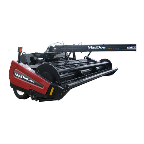
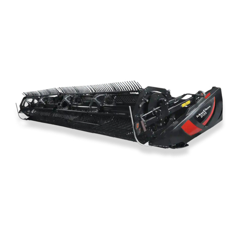
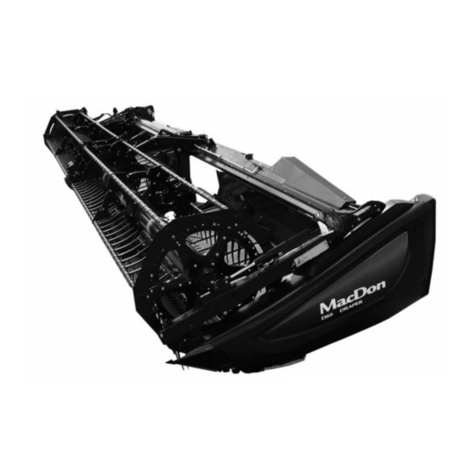
MacDon PW8 User manual

PW8
Pick-Up Header
Operator’s Manual
215575 Revision B
Original Instruction
The Harvesting Specialists.

PW8 Pick-Up Header
Published July 2021.
© 2021 MacDon Industries, Ltd.
The information in this publication is based on the information available and in effect at the time of printing. MacDon
Industries, Ltd. makes no representation or warranty of any kind, whether expressed or implied, with respect to the
information in this publication. MacDon Industries, Ltd. reserves the right to make changes at any time without notice.
California Proposition 65 Warning
Diesel engine exhaust and some of its constituents are known to the State of California to cause cancer, birth defects, and
other reproductive harm. Battery posts, terminals, and related accessories contain lead and lead components. Wash hands
after handling.

Declaration of Conformity
0DF'RQ,QGXVWULHV/WG
0RUD\ 6WUHHW
:LQQLSHJ 0DQLWRED &DQDGD
5- 6
ϭ
Ϯ ŽŵďŝŶĞ WŝĐŬ-hƉ ,ĞĂĚĞƌ
>@ DĂĐŽŶ Wtϴ
ϰ Ɛ ƉĞƌ ^ŚŝƉƉŝŶŐ ŽĐƵŵĞŶƚ
ϱ DĂLJ ϭϮ ϮϬϮϭ
ϲ ͺͺͺͺͺͺͺͺͺͺͺͺͺͺͺͺͺͺͺͺͺͺͺͺͺͺͺͺͺ
ĚƌŝĞŶŶĞ dĂŶŬĞƵ
WƌŽĚƵĐƚ /ŶƚĞŐƌŝƚLJ
E
tĞ ϭ
ĞĐůĂƌĞ ƚŚĂƚ ƚŚĞ ƉƌŽĚƵĐƚ
DĂĐŚŝŶĞ dLJƉĞ Ϯ
EĂŵĞ ΘDŽĚĞů ϯ
^ĞƌŝĂů EƵŵďĞƌ;ƐͿ ϰ
ĨƵůĮůƐ Ăůů ƚŚĞ ƌĞůĞǀĂŶƚ ƉƌŽǀŝƐŝŽŶƐ ŽĨ ƚŚĞ ŝƌĞĐƟǀĞ
ϮϬϬϲϰϮ
,ĂƌŵŽŶŝnjĞĚ ƐƚĂŶĚĂƌĚƐ ƵƐĞĚ ĂƐ ƌĞĨĞƌƌĞĚ ƚŽ ŝŶ ƌƟĐůĞ
ϳ;ϮͿ
E /^K ϰϮϱϰ-ϭϮϬϭϯ
E /^K ϰϮϱϰ-ϳϮϬϬϵ
WůĂĐĞ ĂŶĚ ĚĂƚĞ ŽĨ ĚĞĐůĂƌĂƟŽŶ ϱ
/ĚĞŶƟƚLJ ĂŶĚ ƐŝŐŶĂƚƵƌĞ ŽĨ ƚŚĞ ƉĞƌƐŽŶ ĞŵƉŽǁĞƌĞĚ ƚŽ
ĚƌĂǁ ƵƉ ƚŚĞ ĚĞĐůĂƌĂƟŽŶ ϲ
EĂŵĞ ĂŶĚ ĂĚĚƌĞƐƐ ŽĨ ƚŚĞ ƉĞƌƐŽŶ ĂƵƚŚŽƌŝnjĞĚ ƚŽ
ĐŽŵƉŝůĞ ƚŚĞ ƚĞĐŚŶŝĐĂů ĮůĞ
ĞŶĞĚŝŬƚ ǀŽŶ ZŝĞĚĞƐĞů
'ĞŶĞƌĂů DĂŶĂŐĞƌ DĂĐŽŶ ƵƌŽƉĞ 'ŵď,
,ĂŐĞŶĂƵĞƌ ^ƚƌĂƘĞ ϱϵ
ϲϱϮϬϯ tŝĞƐďĂĚĞŶ ;'ĞƌŵĂŶLJͿ
ďǀŽŶƌŝĞĚĞƐĞůΛŵĂĐĚŽŶĐŽŵ
'
ʻϭ
˃Ϯ
ʻϯ
ˁ;Ϳϰ
ϮϬϬϲϰϮK
ʰ
ϳ;ϮͿ
E /^K ϰϮϱϰ-ϭϮϬϭϯ
E /^K ϰϮϱϰ-ϳϮϬϬϵ
ʺϱ
ʰ
ϲ
ʰ
ʥˀ
˄DĂĐŽŶ ƵƌŽƉĞ 'ŵď,
,ĂŐĞŶĂƵĞƌ ^ƚƌĂƘĞ ϱϵ
ϲϱϮϬϯ tŝĞƐďĂĚĞŶ ;ʧͿ
ďǀŽŶƌŝĞĚĞƐĞůΛŵĂĐĚŽŶĐŽŵ
sŝ ϭ
ĞƌŬůčƌĞƌ Ăƚ ƉƌĚƵŬƚĞƚ
DĂƐŬŝŶƚLJƉĞ Ϯ
EĂǀŶ ŽŐ ŵŽĚĞů ϯ
^ĞƌŝĞŶƵŵŵĞƌ ;-ŶƵŵƌĞͿ ϰ
KƉĨLJůĚĞƌ ĂůůĞ ďĞƐƚĞŵŵĞůƐĞƌ ŝĚŝƌĞŬƟǀ
ϮϬϬϲϰϮ&
ŶǀĞŶĚƚĞ ŚĂƌŵŽŶŝƐĞƌĞĚĞ ƐƚĂŶĚĂƌĚĞƌ ƐŽŵ ŚĞŶǀŝƐƚ
Ɵů ŝƉĂƌĂŐƌĂĨϳ;ϮͿ
E /^K ϰϮϱϰ-ϭϮϬϭϯ
E /^K ϰϮϱϰ-ϳϮϬϬϵ
^ƚĞĚ ŽŐ ĚĂƚŽ ĨŽƌ ĞƌŬůčƌŝŶŐĞŶ ϱ
/ĚĞŶƟƚĞƚ ƉĊ ŽŐ ƵŶĚĞƌƐŬƌŝŌ ĨƌĂ ĚĞŶ ƉĞƌƐŽŶ ƐŽŵ Ğƌ
ďĞŵLJŶĚŝŐĞƚ Ɵů Ăƚ ƵĚĂƌďĞũĚĞ ĞƌŬůčƌŝŶŐĞŶ ϲ
EĂǀŶ ŽŐ ĂĚƌĞƐƐĞ ƉĊ ĚĞŶ ƉĞƌƐŽŶ ƐŽŵ Ğƌ ďĞŵLJŶĚŝŐĞƚ
Ɵů Ăƚ ƵĚĂƌďĞũĚĞ ĚĞŶ ƚĞŬŶŝƐŬĞ Įů
ĞŶĞĚŝŬƚ ǀŽŶ ZŝĞĚĞƐĞů
ŝƌĞŬƚƆƌ DĂĐŽŶ ƵƌŽƉĞ 'ŵď,
,ĂŐĞŶĂƵĞƌ ^ƚƌĂƘĞ ϱϵ
-ϲϱϮϬϯ tŝĞƐďĂĚĞŶ ;dLJƐŬůĂŶĚͿ
ďǀŽŶƌŝĞĚĞƐĞůΛŵĂĐĚŽŶĐŽŵ
tŝƌ ϭ
ƌŬůćƌĞŶ ŚŝĞƌŵŝƚ ĚĂƐƐ ĚĂƐ WƌŽĚƵŬƚ
DĂƐĐŚŝŶĞŶƚLJƉ Ϯ
EĂŵĞ ΘDŽĚĞůů ϯ
^ĞƌŝĞŶŶƵŵŵĞƌ ;ŶͿ ϰ
ĂůůĞ ƌĞůĞǀĂŶƚĞŶ sŽƌƐĐŚƌŝŌĞŶ ĚĞƌ ZŝĐŚƚůŝŶŝĞ
ϮϬϬϲϰϮ' ĞƌĨƺůůƚ
,ĂƌŵŽŶŝƐŝĞƌƚĞ ^ƚĂŶĚĂƌĚƐ ǁƵƌĚĞŶ ǁŝĞ ŝŶ ĨŽůŐĞŶĚĞŶ
ƌƟŬĞůŶ ĂŶŐĞŐĞďĞŶ ǀĞƌǁĞŶĚĞƚϳ;ϮͿ
E /^K ϰϮϱϰ-ϭϮϬϭϯ
E /^K ϰϮϱϰ-ϳϮϬϬϵ
Kƌƚ ƵŶĚ ĂƚƵŵ ĚĞƌ ƌŬůćƌƵŶŐ ϱ
EĂŵĞ ƵŶĚ hŶƚĞƌƐĐŚƌŝŌ ĚĞƌ WĞƌƐŽŶ ĚŝĞ ĚĂnjƵ ďĞĨƵŐƚ
ŝƐƚ ĚŝĞ ƌŬůćƌƵŶŐ ĂƵƐnjƵƐƚĞůůĞŶ ϲ
EĂŵĞ ƵŶĚ ŶƐĐŚƌŝŌ ĚĞƌ WĞƌƐŽŶ ĚŝĞ ĚĂnjƵ ďĞƌĞĐŚƟŐƚ
ŝƐƚ ĚŝĞ ƚĞĐŚŶŝƐĐŚĞŶ hŶƚĞƌůĂŐĞŶ njƵ ĞƌƐƚĞůůĞŶ
ĞŶĞĚŝŬƚ ǀŽŶ ZŝĞĚĞƐĞů
'ĞŶĞƌĂů DĂŶĂŐĞƌ DĂĐŽŶ ƵƌŽƉĞ 'ŵď,
,ĂŐĞŶĂƵĞƌ ^ƚƌĂƘĞ ϱϵ
ϲϱϮϬϯ tŝĞƐďĂĚĞŶ
ďǀŽŶƌŝĞĚĞƐĞůΛŵĂĐĚŽŶĐŽŵ
^
EŽƐŽƚƌŽƐ ϭ
ĚĞĐůĂƌĂŵŽƐ ƋƵĞ Ğů ƉƌŽĚƵĐƚŽ
dŝƉŽ ĚĞ ŵĄƋƵŝŶĂ Ϯ
EŽŵďƌĞ LJŵŽĚĞůŽ ϯ
EƷŵĞƌŽƐ ĚĞ ƐĞƌŝĞ ϰ
ĐƵŵƉůĞ ĐŽŶ ƚŽĚĂƐ ůĂƐ ĚŝƐƉŽƐŝĐŝŽŶĞƐ ƉĞƌƟŶĞŶƚĞƐ ĚĞ ůĂ
ĚŝƌĞĐƚƌŝnj ϮϬϬϲϰϮ
^Ğ ƵƟůŝnjĂƌŽŶ ŶŽƌŵĂƐ ĂƌŵŽŶŝnjĂĚĂƐ ƐĞŐƷŶ ůŽ ĚŝƐƉƵĞƐƚŽ
ĞŶ Ğů ĂƌơĐƵůŽ ϳ;ϮͿ
E /^K ϰϮϱϰ-ϭϮϬϭϯ
E /^K ϰϮϱϰ-ϳϮϬϬϵ
>ƵŐĂƌ LJĨĞĐŚĂ ĚĞ ůĂ ĚĞĐůĂƌĂĐŝſŶ ϱ
/ĚĞŶƟĚĂĚ LJĮƌŵĂ ĚĞ ůĂ ƉĞƌƐŽŶĂ ĨĂĐƵůƚĂĚĂ ƉĂƌĂ ĚƌĂǁ
ƌĞĚĂĐƚĂƌ ůĂ ĚĞĐůĂƌĂĐŝſŶ ϲ
EŽŵďƌĞ LJĚŝƌĞĐĐŝſŶ ĚĞ ůĂ ƉĞƌƐŽŶĂ ĂƵƚŽƌŝnjĂĚĂ ƉĂƌĂ
ĞůĂďŽƌĂƌ Ğů ĞdžƉĞĚŝĞŶƚĞ ƚĠĐŶŝĐŽ
ĞŶĞĚŝŬƚ ǀŽŶ ZŝĞĚĞƐĞů
'ĞƌĞŶƚĞ ŐĞŶĞƌĂů - DĂĐŽŶ ƵƌŽƉĞ 'ŵď,
,ĂŐĞŶĂƵĞƌ ^ƚƌĂƘĞ ϱϵ
ϲϱϮϬϯ tŝĞƐďĂĚĞŶ ;ůĞŵĂŶŝĂͿ
ďǀŽŶƌŝĞĚĞƐĞůΛŵĂĐĚŽŶĐŽŵ
ĞĐůĂƌĂƟŽŶ ŽĨ ŽŶĨŽƌŵŝƚLJ
d
DĞŝĞ ϭ
ĚĞŬůĂƌĞĞƌŝŵĞ Ğƚ ƚŽŽĚĞ
^ĞĂĚŵĞ ƚƺƺƉ Ϯ
Eŝŵŝ ũĂ ŵƵĚĞů ϯ
^ĞĞƌŝĂŶƵŵďƌŝĚ ϰ
ǀĂƐƚĂď ŬƁŝŐŝůĞ ĚŝƌĞŬƟŝǀŝ ϮϬϬϲϰϮm ĂƐũĂŬŽŚĂƐƚĞůĞ
ƐćƚĞƚĞůĞ
<ĂƐƵƚĂƚƵĚ ŽŶ ũćƌŐŶĞǀĂŝĚ ŚĂƌŵŽŶŝƐĞĞƌŝƚƵĚ ƐƚĂŶĚ-
ĂƌĚĞŝĚ ŵŝůůĞůĞ ŽŶ ǀŝŝĚĂƚƵĚ ŬĂ ƉƵŶŬƟƐ ϳ;ϮͿ
E /^K ϰϮϱϰ-ϭϮϬϭϯ
E /^K ϰϮϱϰ-ϳϮϬϬϵ
ĞŬůĂƌĂƚƐŝŽŽŶŝ ŬŽŚƚ ũĂ ŬƵƵƉćĞǀ ϱ
ĞŬůĂƌĂƚƐŝŽŽŶŝ ŬŽŽƐƚĂŵŝƐĞŬƐ ǀŽůŝƚĂƚƵĚ ŝƐŝŬƵ Ŷŝŵŝ ũĂ
ĂůůŬŝƌŝ ϲ
dĞŚŶŝůŝƐĞ ĚŽŬƵŵĞŶĚŝ ŬŽŽƐƚĂŵŝƐĞŬƐ ǀŽůŝƚĂƚƵĚŝƐŝŬƵ
Ŷŝŵŝ ũĂ ĂĂĚƌĞƐƐ
ĞŶĞĚŝŬƚ ǀŽŶ ZŝĞĚĞƐĞů
WĞĂĚŝƌĞŬƚŽƌ DĂĐŽŶ ƵƌŽƉĞ 'ŵď,
,ĂŐĞŶĂƵĞƌ ^ƚƌĂƘĞ ϱϵ
ϲϱϮϬϯ tŝĞƐďĂĚĞŶ ;^ĂŬƐĂŵĂĂͿ
ďǀŽŶƌŝĞĚĞƐĞůΛŵĂĐĚŽŶĐŽŵ
DLJ ϭ
WƌŽŚůĂƓƵũĞŵĞ ǎĞ ƉƌŽĚƵŬƚ
dLJƉ njĂƎşnjĞŶş Ϯ
EĄnjĞǀ ĂŵŽĚĞů ϯ
^ĠƌŝŽǀĠ;ĄͿ ēşƐůŽͿĂͿ ϰ
ƐƉůŸƵũĞ ǀƓĞĐŚŶĂ ƌĞůĞǀĂŶƚŶş ƵƐƚĂŶŽǀĞŶş ƐŵĢƌŶŝĐĞ
ϮϬϬϲϰϮ
LJůLJ ƉŽƵǎŝƚLJ ŚĂƌŵŽŶŝnjŽǀĂŶĠ ƐƚĂŶĚĂƌĚLJ ũĂŬ ũĞ ƵǀĞ-
ĚĞŶŽ ǀēůĄŶŬƵ ϳ;ϮͿ
E /^K ϰϮϱϰ-ϭϮϬϭϯ
E /^K ϰϮϱϰ-ϳϮϬϬϵ
DşƐƚŽ ĂĚĂƚƵŵ ƉƌŽŚůĄƓĞŶş ϱ
/ĚĞŶƟƚĂ ĂƉŽĚƉŝƐ ŽƐŽďLJ ŽƉƌĄǀŶĢŶĠ ŬǀLJĚĄŶş
ƉƌŽŚůĄƓĞŶş ϲ
:ŵĠŶŽ ĂĂĚƌĞƐĂ ŽƐŽďLJ ŽƉƌĄǀŶĢŶĠ ŬǀLJƉůŶĢŶş ƚĞĐŚŶŝ-
ĐŬĠŚŽ ƐŽƵďŽƌƵ
ĞŶĞĚŝŬƚ ǀŽŶ ZŝĞĚĞƐĞů
ŐĞŶĞƌĄůŶş ƎĞĚŝƚĞů DĂĐŽŶ ƵƌŽƉĞ 'ŵď,
,ĂŐĞŶĂƵĞƌ ^ƚƌĂƘĞ ϱϵ
ϲϱϮϬϯ tŝĞƐďĂĚĞŶ ;EĢŵĞĐŬŽͿ
ďǀŽŶƌŝĞĚĞƐĞůΛŵĂĐĚŽŶĐŽŵ
&Z
EŽƵƐ ƐŽƵƐƐŝŐŶĠƐ ϭ
ĠĐůĂƌŽŶƐ ƋƵĞ ůĞ ƉƌŽĚƵŝƚ
dLJƉĞ ĚĞ ŵĂĐŚŝŶĞ Ϯ
EŽŵ Ğƚ ŵŽĚğůĞ ϯ
EƵŵĠƌŽ;ƐͿ ĚĞ ƐĠƌŝĞ ϰ
Ɛƚ ĐŽŶĨŽƌŵĞ ăƚŽƵƚĞƐ ůĞƐ ĚŝƐƉŽƐŝƟŽŶƐ ƉĞƌƟŶĞŶƚĞƐ ĚĞ
ůĂ ĚŝƌĞĐƟǀĞ ϮϬϬϲϰϮ
hƟůŝƐĂƟŽŶ ĚĞƐ ŶŽƌŵĞƐ ŚĂƌŵŽŶŝƐĠĞƐ ĐŽŵŵĞ ŝŶĚŝƋƵĠ
ĚĂŶƐ ůΖƌƟĐůĞ ϳ;ϮͿ
E /^K ϰϮϱϰ-ϭϮϬϭϯ
E /^K ϰϮϱϰ-ϳϮϬϬϵ
>ŝĞƵ Ğƚ ĚĂƚĞ ĚĞ ůĂ ĚĠĐůĂƌĂƟŽŶ ϱ
/ĚĞŶƟƚĠ Ğƚ ƐŝŐŶĂƚƵƌĞ ĚĞ ůĂ ƉĞƌƐŽŶŶĞ ĂLJĂŶƚ ƌĞĕƵ ůĞ
ƉŽƵǀŽŝƌ ĚĞƌĠĚŝŐĞƌ ĐĞƩĞ ĚĠĐůĂƌĂƟŽŶ ϲ
EŽŵ Ğƚ ĂĚƌĞƐƐĞ ĚĞ ůĂ ƉĞƌƐŽŶŶĞ ĂƵƚŽƌŝƐĠĞ ăĐŽŶƐƟ-
ƚƵĞƌ ůĞ ĚŽƐƐŝĞƌ ƚĞĐŚŶŝƋƵĞ
ĞŶĞĚŝŬƚ ǀŽŶ ZŝĞĚĞƐĞů
ŝƌĞĐƚĞƵƌ ŐĠŶĠƌĂů DĂĐŽŶ ƵƌŽƉĞ 'ŵď,
,ĂŐĞŶĂƵĞƌ ^ƚƌĂƘĞ ϱϵ
ϲϱϮϬϯ tŝĞƐďĂĚĞŶ ;ůůĞŵĂŐŶĞͿ
ďǀŽŶƌŝĞĚĞƐĞůΛŵĂĐĚŽŶĐŽŵ
215575 iRevision B

ĞĐůĂƌĂƟŽŶ ŽĨ ŽŶĨŽƌŵŝƚLJ
,h
Dŝ ϭ
njĞŶŶĞů ŬŝũĞůĞŶƚũƺŬ ŚŽŐLJ ĂŬƂǀĞƚŬĞnjƅ ƚĞƌŵĠŬ
'ĠƉ ơƉƵƐĂ Ϯ
EĠǀ ĠƐ ŵŽĚĞůů ϯ
^njĠƌŝĂƐnjĄŵ;ŽŬͿ ϰ
ƚĞůũĞƐşƟ ĂŬƂǀĞƚŬĞnjƅ ŝƌĄŶLJĞůǀ ƂƐƐnjĞƐ ǀŽŶĂƚŬŽnjſ
ĞůƅşƌĄƐĂŝƚ ϮϬϬϲϰϮ<
nj ĂůĄďďŝ ŚĂƌŵŽŶŝnjĄůƚ ƐnjĂďǀĄŶLJŽŬ ŬĞƌƺůƚĞŬ
ĂůŬĂůŵĂnjĄƐƌĂĂϳ;ϮͿ ĐŝŬŬĞůLJ ƐnjĞƌŝŶƚ
E /^K ϰϮϱϰ-ϭϮϬϭϯ
E /^K ϰϮϱϰ-ϳϮϬϬϵ
ŶLJŝůĂƚŬŽnjĂƩĠƚĞů ŝĚĞũĞ ĠƐ ŚĞůLJĞ ϱ
njŽŶ ƐnjĞŵĠůLJ ŬŝůĠƚĞ ĠƐ ĂůĄşƌĄƐĂ ĂŬŝ ũŽŐŽƐƵůƚ Ă
ŶLJŝůĂƚŬŽnjĂƚ ĞůŬĠƐnjşƚĠƐĠƌĞ ϲ
njŽŶ ƐnjĞŵĠůLJ ŶĞǀĞ ĠƐ ĂůĄşƌĄƐĂ ĂŬŝ ĨĞůŚĂƚĂůŵĂnjŽƩĂ
ŵƾƐnjĂŬŝ ĚŽŬƵŵĞŶƚĄĐŝſ ƂƐƐnjĞĄůůşƚĄƐĄƌĂ
ĞŶĞĚŝŬƚ ǀŽŶ ZŝĞĚĞƐĞů
sĞnjĠƌŝŐĂnjŐĂƚſ DĂĐŽŶ ƵƌŽƉĞ 'ŵď,
,ĂŐĞŶĂƵĞƌ ^ƚƌĂƘĞ ϱϵ
ϲϱϮϬϯ tŝĞƐďĂĚĞŶ ;EĠŵĞƚŽƌƐnjĄŐͿ
ďǀŽŶƌŝĞĚĞƐĞůΛŵĂĐĚŽŶĐŽŵ
>d
DĞƐ ϭ
WĂƌĞŝƓŬŝĂŵĞ ŬĂĚ ƓŝƐ ƉƌŽĚƵŬƚĂƐ
DĂƓŝŶŽƐ ƟƉĂƐ Ϯ
WĂǀĂĚŝŶŝŵĂƐ ŝƌ ŵŽĚĞůŝƐ ϯ
^ĞƌŝũŽƐ ŶƵŵĞƌŝƐ ;-ŝĂŝͿ ϰ
ĂƟƟŶŬĂ ƚĂŝŬŽŵƵƐ ƌĞŝŬĂůĂǀŝŵƵƐ ƉĂŐĂů ŝƌĞŬƚLJǀČ
ϮϬϬϲϰϮ
EĂƵĚŽũĂŵŝ ŚĂƌŵŽŶŝnjƵŽƟ ƐƚĂŶĚĂƌƚĂŝ ŬĂŝ ŶƵƌŽĚŽŵĂ
ƐƚƌĂŝƉƐŶLJũĞ ϳ;ϮͿ
E /^K ϰϮϱϰ-ϭϮϬϭϯ
E /^K ϰϮϱϰ-ϳϮϬϬϵ
ĞŬůĂƌĂĐŝũŽƐ ǀŝĞƚĂ ŝƌ ĚĂƚĂ ϱ
ƐŵĞŶƐ ƚĂƉĂƚLJďĦƐ ĚƵŽŵĞŶLJƐ ŝƌ ƉĂƌĂƓĂƐ ĂƐŵĞŶƐ
ťŐĂůŝŽƚŽ ƐƵĚĂƌLJƟ ƓŝČ ĚĞŬůĂƌĂĐŝũČ ϲ
sĂƌĚĂƐ ŝƌ ƉĂǀĂƌĚĦ ĂƐŵĞŶƐ ŬƵƌŝƐ ťŐĂůŝŽƚĂƐ ƐƵĚĂƌLJƟ Ɠť
ƚĞĐŚŶŝŶť ĨĂŝůČ
ĞŶĞĚŝŬƚ ǀŽŶ ZŝĞĚĞƐĞů
'ĞŶĞƌĂůŝŶŝƐ ĚŝƌĞŬƚŽƌŝƵƐ DĂĐŽŶ ƵƌŽƉĞ 'ŵď,
,ĂŐĞŶĂƵĞƌ ^ƚƌĂƘĞ ϱϵ
ϲϱϮϬϯ tŝĞƐďĂĚĞŶ ;sŽŬŝĞƟũĂͿ
ďǀŽŶƌŝĞĚĞƐĞůΛŵĂĐĚŽŶĐŽŵ
>s
DĤƐ ϭ
ĞŬůĂƌĤũĂŵ ŬĂ ƉƌŽĚƵŬƚƐ
DĂƓţŶĂƐ ƟƉƐ Ϯ
EŽƐĂƵŬƵŵƐ ƵŶ ŵŽĚĞůŝƐ ϯ
^ĤƌŝũĂƐ ŶƵŵƵƌƐ;ͲŝͿ ϰ
ƚďŝůƐƚ ǀŝƐĈŵ ďƻƟƐŬĂũĈŵ ŝƌĞŬƤǀĂƐϮϬϬϲϰϮ<
ƉƌĂƐţďĈŵ
WŝĞŵĤƌŽƟ ƓĈĚŝ ƐĂƐŬĂźŽƟĞ ƐƚĂŶĚĂƌƟ ŬĈ ŵŝŶĤƚƐ
ϳ ƉĂŶƚĂ Ϯ ƉƵŶŬƚĈ
E /^K ϰϮϱϰ-ϭϮϬϭϯ
E /^K ϰϮϱϰ-ϳϮϬϬϵ
ĞŬůĂƌĈĐŝũĂƐ ƉĂƌĂŬƐƤƓĂŶĂƐ ǀŝĞƚĂ ƵŶ ĚĂƚƵŵƐ ϱ
dĈƐ ƉĞƌƐŽŶĂƐ ǀĈƌĚƐ ƵnjǀĈƌĚƐ ƵŶ ƉĂƌĂŬƐƚƐ ŬĂƐ ŝƌ
ƉŝůŶǀĂƌŽƚĂƐĂŐĂƚĂǀŽƚ ƓŽ ĚĞŬůĂƌĈĐŝũƵ ϲ
dĈƐ ƉĞƌƐŽŶĂƐ ǀĈƌĚƐ ƵnjǀĈƌĚƐ ƵŶ ĂĚƌĞƐĞ ŬĂƐ ŝƌ
ƉŝůŶǀĂƌŽƚĂ ƐĂƐƚĈĚţƚ ƚĞŚŶŝƐŬŽ ĚŽŬƵŵĞŶƚĈĐŝũƵ
ĞŶĞĚŝŬƚƐ ĨŽŶ ZţĚţnjĞůƐ
+ĞŶĞƌĈůĚŝƌĞŬƚŽƌƐ DĂĐŽŶ ƵƌŽƉĞ 'ŵď,
,ĂŐĞŶĂƵĞƌ ^ƚƌĂƘĞ ϱϵ
ϲϱϮϬϯ tŝĞƐďĂĚĞŶ ;sĈĐŝũĂͿ
ďǀŽŶƌŝĞĚĞƐĞůΛŵĂĐĚŽŶĐŽŵ
E>
tŝũ ϭ
sĞƌŬůĂƌĞŶ ĚĂƚ ŚĞƚ ƉƌŽĚƵĐƚ
DĂĐŚŝŶĞƚLJƉĞ Ϯ
EĂĂŵ ĞŶ ŵŽĚĞů ϯ
^ĞƌŝĞŶƵŵŵĞƌ;ƐͿ ϰ
ǀŽůĚŽĞƚ ĂĂŶ ĂůůĞ ƌĞůĞǀĂŶƚĞ ďĞƉĂůŝŶŐĞŶ ǀĂŶ ĚĞ
ZŝĐŚƚůŝũŶ ϮϬϬϲϰϮ
'ĞŚĂƌŵŽŶŝƐĞĞƌĚĞ ŶŽƌŵĞŶ ƚŽĞŐĞƉĂƐƚ njŽĂůƐ ǀĞƌŵĞůĚ
ŝŶ ƌƟŬĞůϳ;ϮͿ
E /^K ϰϮϱϰ-ϭϮϬϭϯ
E /^K ϰϮϱϰ-ϳϮϬϬϵ
WůĂĂƚƐ ĞŶ ĚĂƚƵŵ ǀĂŶ ǀĞƌŬůĂƌŝŶŐ ϱ
EĂĂŵ ĞŶ ŚĂŶĚƚĞŬĞŶŝŶŐ ǀĂŶ ĚĞ ďĞǀŽĞŐĚĞ ƉĞƌƐŽŽŶ Žŵ
ĚĞ ǀĞƌŬůĂƌŝŶŐ ŽƉ ƚĞ ƐƚĞůůĞŶ ϲ
EĂĂŵ ĞŶ ĂĚƌĞƐ ǀĂŶ ĚĞ ŐĞĂƵƚŽƌŝƐĞĞƌĚĞ ƉĞƌƐŽŽŶ Žŵ
ŚĞƚ ƚĞĐŚŶŝƐĐŚ ĚŽƐƐŝĞƌ ƐĂŵĞŶ ƚĞ ƐƚĞůůĞŶ
ĞŶĞĚŝŬƚ ǀŽŶ ZŝĞĚĞƐĞů
ůŐĞŵĞĞŶ ĚŝƌĞĐƚĞƵƌ DĂĐŽŶ ƵƌŽƉĞ 'ŵď,
,ĂŐĞŶĂƵĞƌ ^ƚƌĂƘĞ ϱϵ
ϲϱϮϬϯ tŝĞƐďĂĚĞŶ ;ƵŝƚƐůĂŶĚͿ
ďǀŽŶƌŝĞĚĞƐĞůΛŵĂĐĚŽŶĐŽŵ
WK
DLJ ŶŝǏĞũ ƉŽĚƉŝƐĂŶŝ ϭ
KƑǁŝĂĚĐnjĂŵLJ ǏĞ ƉƌŽĚƵŬƚ
dLJƉ ƵƌnjČĚnjĞŶŝĂ Ϯ
EĂnjǁĂ ŝŵŽĚĞů ϯ
EƵŵĞƌ ƐĞƌLJũŶLJŶƵŵĞƌLJ ƐĞƌLJũŶĞ ϰ
ƐƉĞųŶŝĂ ǁƐnjLJƐƚŬŝĞ ŽĚƉŽǁŝĞĚŶŝĞ ƉƌnjĞƉŝƐLJ ĚLJƌĞŬƚLJǁLJ
ϮϬϬϲϰϮt
ĂƐƚŽƐŽǁĂůŝƑŵLJ ŶĂƐƚħƉƵũČĐĞ ;njŚĂƌŵŽŶŝnjŽǁĂŶĞͿ
ŶŽƌŵLJ njŐŽĚŶŝĞ njĂƌƚLJŬƵųĞŵϳ;ϮͿ
E /^K ϰϮϱϰ-ϭϮϬϭϯ
E /^K ϰϮϱϰ-ϳϮϬϬϵ
ĂƚĂ ŝŵŝĞũƐĐĞ ŽƑǁŝĂĚĐnjĞŶŝĂ ϱ
/ŵŝħ ŝŶĂnjǁŝƐŬŽ ŽƌĂnj ƉŽĚƉŝƐ ŽƐŽďLJ ƵƉŽǁĂǏŶŝŽŶĞũ ĚŽ
ƉƌnjLJŐŽƚŽǁĂŶŝĂ ĚĞŬůĂƌĂĐũŝ ϲ
/ŵŝħ ŝŶĂnjǁŝƐŬŽ ŽƌĂnj ĂĚƌĞƐ ŽƐŽďLJ ƵƉŽǁĂǏŶŝŽŶĞũ ĚŽ
ƉƌnjLJŐŽƚŽǁĂŶŝĂ ĚŽŬƵŵĞŶƚĂĐũŝ ƚĞĐŚŶŝĐnjŶĞũ
ĞŶĞĚŝŬƚ ǀŽŶ ZŝĞĚĞƐĞů
LJƌĞŬƚŽƌ ŐĞŶĞƌĂůŶLJ DĂĐŽŶ ƵƌŽƉĞ 'ŵď,
,ĂŐĞŶĂƵĞƌ ^ƚƌĂƘĞ ϱϵ
ϲϱϮϬϯ tŝĞƐďĂĚĞŶ ;EŝĞŵĐLJͿ
ďǀŽŶƌŝĞĚĞƐĞůΛŵĂĐĚŽŶĐŽŵ
ZK
EŽŝ ϭ
ĞĐůĂƌĉŵ Đĉ ƵƌŵĉƚŽƌƵů ƉƌŽĚƵƐ
dŝƉƵů ŵĂƕŝŶŝŝ Ϯ
ĞŶƵŵŝƌĞĂ ƕŝ ŵŽĚĞůƵů ϯ
EƵŵĉƌ ;ŶƵŵĞƌĞͿ ƐĞƌŝĞ ϰ
ĐŽƌĞƐƉƵŶĚĞ ƚƵƚƵƌŽƌ ĚŝƐƉŽnjŝƜŝŝůŽƌ ĞƐĞŶƜŝĂůĞ ĂůĞ
ĚŝƌĞĐƟǀĞŝ ϮϬϬϲϰϮ
Ƶ ĨŽƐƚ ĂƉůŝĐĂƚĞ ƵƌŵĉƚŽĂƌĞůĞ ƐƚĂŶĚĂƌĚĞ ĂƌŵŽŶŝnjĂƚĞ
ĐŽŶĨŽƌŵ ĂƌƟĐŽůƵůƵŝ ϳ;ϮͿ
E /^K ϰϮϱϰ-ϭϮϬϭϯ
E /^K ϰϮϱϰ-ϳϮϬϬϵ
ĂƚĂ ƕŝ ůŽĐƵů ĚĞĐůĂƌĂƜŝĞŝ ϱ
/ĚĞŶƟƚĂƚĞĂ ƕŝ ƐĞŵŶĉƚƵƌĂ ƉĞƌƐŽĂŶĞŝ ŠŵƉƵƚĞƌŶŝĐŝƚĞ
ƉĞŶƚƌƵ ŠŶƚŽĐŵŝƌĞĂ ĚĞĐůĂƌĂƜŝĞŝ ϲ
EƵŵĞůĞ ƕŝ ƐĞŵŶĉƚƵƌĂ ƉĞƌƐŽĂŶĞŝ ĂƵƚŽƌŝnjĂƚĞ ƉĞŶƚƌƵ
ŠŶƚŽĐŵŝƌĞĂ ĐĉƌƜŝŝ ƚĞŚŶŝĐĞ
ĞŶĞĚŝŬƚ ǀŽŶ ZŝĞĚĞƐĞů
DĂŶĂŐĞƌ 'ĞŶĞƌĂů DĂĐŽŶ ƵƌŽƉĞ 'ŵď,
,ĂŐĞŶĂƵĞƌ ^ƚƌĂƘĞ ϱϵ
ϲϱϮϬϯ tŝĞƐďĂĚĞŶ ;'ĞƌŵĂŶŝĂͿ
ďǀŽŶƌŝĞĚĞƐĞůΛŵĂĐĚŽŶĐŽŵ
^s
sŝ ϭ
/ŶƚLJŐĂƌ ĂƩ ƉƌŽĚƵŬƚĞŶ
DĂƐŬŝŶƚLJƉ Ϯ
EĂŵŶ ŽĐŚ ŵŽĚĞůů ϯ
^ĞƌŝĞŶƵŵŵĞƌ ϰ
ƵƉƉĨLJůůĞƌ ĂůůĂ ƌĞůĞǀĂŶƚĂ ǀŝůůŬŽƌ ŝĚŝƌĞŬƟǀĞƚ
ϮϬϬϲϰϮ'
,ĂƌŵŽŶŝĞƌĂĚĞ ƐƚĂŶĚĂƌĚĞƌ ĂŶǀćŶĚƐ ƐĊƐŽŵ ĂŶŐĞƐ ŝ
ĂƌƟŬĞůϳ;ϮͿ
E /^K ϰϮϱϰ-ϭϮϬϭϯ
E /^K ϰϮϱϰ-ϳϮϬϬϵ
WůĂƚƐ ŽĐŚ ĚĂƚƵŵ ĨƂƌ ŝŶƚLJŐĞƚ ϱ
/ĚĞŶƟƚĞƚ ŽĐŚ ƐŝŐŶĂƚƵƌ ĨƂƌ ƉĞƌƐŽŶ ŵĞĚ ďĞĨŽŐĞŶŚĞƚ ĂƩ
ƵƉƉƌćƩĂ ŝŶƚLJŐĞƚ ϲ
EĂŵŶ ŽĐŚ ĂĚƌĞƐƐ ĨƂƌ ƉĞƌƐŽŶ ďĞŚƂƌŝŐ ĂƩƵƉƉƌćƩĂ
ĚĞŶ ƚĞŬŶŝƐŬĂ ĚŽŬƵŵĞŶƚĂƟŽŶĞŶ
ĞŶĞĚŝŬƚ ǀŽŶ ZŝĞĚĞƐĞů
ĚŵŝŶŝƐƚƌĂƟǀ ĐŚĞĨ DĂĐŽŶ ƵƌŽƉĞ 'ŵď,
,ĂŐĞŶĂƵĞƌ ^ƚƌĂƘĞ ϱϵ
ϲϱϮϬϯ tŝĞƐďĂĚĞŶ ;dLJƐŬůĂŶĚͿ
ďǀŽŶƌŝĞĚĞƐĞůΛŵĂĐĚŽŶĐŽŵ
^>
Dŝ ϭ
ŝnjũĂǀůũĂŵŽ ĚĂ ŝnjĚĞůĞŬ
sƌƐƚĂ ƐƚƌŽũĂ Ϯ
/ŵĞ ŝŶ ŵŽĚĞů ϯ
^ĞƌŝũƐŬĂ-ĞƓƚĞǀŝůŬĂ-Ğ ϰ
ƵƐƚƌĞnjĂ ǀƐĞŵ njĂĚĞǀŶŝŵ ĚŽůŽēďĂŵ ŝƌĞŬƟǀĞ
ϮϬϬϲϰϮ^
hƉŽƌĂďůũĞŶŝ ƵƐŬůĂũĞŶŝ ƐƚĂŶĚĂƌĚŝ ŬŽƚ ũĞ ŶĂǀĞĚĞŶŽ ǀ
ēůĞŶƵϳ;ϮͿ
E /^K ϰϮϱϰ-ϭϮϬϭϯ
E /^K ϰϮϱϰ-ϳϮϬϬϵ
<ƌĂũ ŝŶ ĚĂƚƵŵ ŝnjũĂǀĞ ϱ
/ƐƚŽǀĞƚŶŽƐƚ ŝŶ ƉŽĚƉŝƐ ŽƐĞďĞ ŽƉŽůŶŽŵŽēĞŶĞ njĂ
ƉƌŝƉƌĂǀŽ ŝnjũĂǀĞ ϲ
/ŵĞ ŝŶ ŶĂƐůŽǀ ŽƐĞďĞ ƉŽŽďůĂƓēĞŶĞ njĂƉƌŝƉƌĂǀŽ
ƚĞŚŶŝēŶĞ ĚĂƚŽƚĞŬĞ
ĞŶĞĚŝŬƚ ǀŽŶ ZŝĞĚĞƐĞů
'ĞŶĞƌĂůŶŝ ĚŝƌĞŬƚŽƌ DĂĐŽŶ ƵƌŽƉĞ 'ŵď,
,ĂŐĞŶĂƵĞƌ ^ƚƌĂƘĞ ϱϵ
ϲϱϮϬϯ tŝĞƐďĂĚĞŶ ;EĞŵēŝũĂͿ
ďǀŽŶƌŝĞĚĞƐĞůΛŵĂĐĚŽŶĐŽŵ
^<
DLJ ϭ
ƚljŵƚŽ ƉƌĞŚůĂƐƵũĞŵĞ ǎĞ ƚĞŶƚŽ ǀljƌŽďŽŬ
dLJƉ njĂƌŝĂĚĞŶŝĂ Ϯ
EĄnjŽǀ ĂŵŽĚĞů ϯ
sljƌŽďŶĠ ēşƐůŽ ϰ
ƐƉŰŸĂ ƉƌşƐůƵƓŶĠ ƵƐƚĂŶŽǀĞŶŝĂ ĂnjĄŬůĂĚŶĠ ƉŽǎŝĂĚĂǀŬLJ
ƐŵĞƌŶŝĐĞē ϮϬϬϲϰϮ^
WŽƵǎŝƚĠ ŚĂƌŵŽŶŝnjŽǀĂŶĠ ŶŽƌŵLJ ŬƚŽƌĠ ƐĂ ƵǀĄĚnjĂũƷ ǀ
ůĄŶŬƵ ē ϳ;ϮͿ
E /^K ϰϮϱϰ-ϭϮϬϭϯ
E /^K ϰϮϱϰ-ϳϮϬϬϵ
DŝĞƐƚŽ ĂĚĄƚƵŵ ƉƌĞŚůĄƐĞŶŝĂ ϱ
DĞŶŽ ĂƉŽĚƉŝƐ ŽƐŽďLJ ŽƉƌĄǀŶĞŶĞũǀLJƉƌĂĐŽǀĂƛ ƚŽƚŽ
ƉƌĞŚůĄƐĞŶŝĞ ϲ
DĞŶŽ ĂĂĚƌĞƐĂ ŽƐŽďLJ ŽƉƌĄǀŶĞŶĞũnjŽƐƚĂǀŝƛ ƚĞĐŚŶŝĐŬlj
ƐƷďŽƌ
ĞŶĞĚŝŬƚ ǀŽŶ ZŝĞĚĞƐĞů
'ĞŶĞƌĄůŶLJ ƌŝĂĚŝƚĞű DĂĐŽŶ ƵƌŽƉĞ 'ŵď,
,ĂŐĞŶĂƵĞƌ ^ƚƌĂƘĞ ϱϵ
ϲϱϮϬϯ tŝĞƐďĂĚĞŶ ;EĞŵĞĐŬŽͿ
ďǀŽŶƌŝĞĚĞƐĞůΛŵĂĐĚŽŶĐŽŵ
/d
EŽŝ ϭ
ŝĐŚŝĂƌŝĂŵŽ ĐŚĞ ŝů ƉƌŽĚŽƩŽ
dŝƉŽ Ěŝ ŵĂĐĐŚŝŶĂ Ϯ
EŽŵĞ ĞŵŽĚĞůůŽ ϯ
EƵŵĞƌŽ;ŝͿ Ěŝ ƐĞƌŝĞ ϰ
ƐŽĚĚŝƐĨĂ ƚƵƩĞ ůĞ ĚŝƐƉŽƐŝnjŝŽŶŝ ƌŝůĞǀĂŶƟ ĚĞůůĂ ĚŝƌĞƫǀĂ
ϮϬϬϲϰϮ
hƟůŝnjnjŽ ĚĞŐůŝ ƐƚĂŶĚĂƌĚ ĂƌŵŽŶŝnjnjĂƟ ĐŽŵĞ ŝŶĚŝĐĂƚŽ
ŶĞůůΖƌƟĐŽůŽ ϳ;ϮͿ
E /^K ϰϮϱϰ-ϭϮϬϭϯ
E /^K ϰϮϱϰ-ϳϮϬϬϵ
>ƵŽŐŽ ĞĚĂƚĂ ĚĞůůĂ ĚŝĐŚŝĂƌĂnjŝŽŶĞ ϱ
EŽŵĞ ĞĮƌŵĂ ĚĞůůĂ ƉĞƌƐŽŶĂ ĂƵƚŽƌŝnjnjĂƚĂ ĂƌĞĚŝŐĞƌĞ ůĂ
ĚŝĐŚŝĂƌĂnjŝŽŶĞ ϲ
EŽŵĞ ĞƉĞƌƐŽŶĂ ĂƵƚŽƌŝnjnjĂƚĂ ĂĐŽŵƉŝůĂƌĞ ŝů ĮůĞ
ƚĞĐŶŝĐŽ
ĞŶĞĚŝŬƚ ǀŽŶ ZŝĞĚĞƐĞů
'ĞŶĞƌĂů DĂŶĂŐĞƌ DĂĐŽŶ ƵƌŽƉĞ 'ŵď,
,ĂŐĞŶĂƵĞƌ ^ƚƌĂƘĞ ϱϵ
ϲϱϮϬϯ tŝĞƐďĂĚĞŶ ;'ĞƌŵĂŶŝĂͿ
ďǀŽŶƌŝĞĚĞƐĞůΛŵĂĐĚŽŶĐŽŵ
Wd
EſƐ ϭ
ĞĐůĂƌĂŵŽƐ ƋƵĞ ŽƉƌŽĚƵƚŽ
dŝƉŽ ĚĞ ŵĄƋƵŝŶĂ Ϯ
EŽŵĞ ĞDŽĚĞůŽ ϯ
EƷŵĞƌŽ;ƐͿ ĚĞ ^ĠƌŝĞ ϰ
ĐƵŵƉƌĞ ƚŽĚĂƐ ĂƐ ĚŝƐƉŽƐŝĕƁĞƐ ƌĞůĞǀĂŶƚĞƐ ĚĂ ŝƌĞĐƟǀĂ
ϮϬϬϲϰϮ
EŽƌŵĂƐ ŚĂƌŵŽŶŝnjĂĚĂƐ ĂƉůŝĐĂĚĂƐ ĐŽŶĨŽƌŵĞ ƌĞĨĞƌŝĚŽ
ŶŽ ƌƟŐŽ ϳ;ϮͿ
E /^K ϰϮϱϰ-ϭϮϬϭϯ
E /^K ϰϮϱϰ-ϳϮϬϬϵ
>ŽĐĂů ĞĚĂƚĂ ĚĂ ĚĞĐůĂƌĂĕĆŽ ϱ
/ĚĞŶƟĚĂĚĞ ĞĂƐƐŝŶĂƚƵƌĂ ĚĂ ƉĞƐƐŽĂ ĂƵƚŽƌŝnjĂĚĂ Ă
ĞůĂďŽƌĂƌ ĂĚĞĐůĂƌĂĕĆŽ ϲ
EŽŵĞ ĞĞŶĚĞƌĞĕŽ ĚĂ ƉĞƐƐŽĂ ĂƵƚŽƌŝnjĂĚĂ ĂĐŽŵƉŝůĂƌ Ž
ĮĐŚĞŝƌŽ ƚĠĐŶŝĐŽ
ĞŶĞĚŝŬƚ ǀŽŶ ZŝĞĚĞƐĞů
'ĞƌĞŶƚĞ 'ĞƌĂů DĂĐŽŶ ƵƌŽƉĂ >ƚĚĂ
,ĂŐĞŶĂƵĞƌ ^ƚƌĂƘĞ ϱϵ
ϲϱϮϬϯ tŝĞƐďĂĚĞŶ ;ůĞŵĂŶŚĂͿ
ďǀŽŶƌŝĞĚĞƐĞůΛŵĂĐĚŽŶĐŽŵ
^Z
Dŝ ϭ
/njũĂǀůũƵũĞŵŽ ĚĂ ƉƌŽŝnjǀŽĚ
dŝƉ ŵĂƓŝŶĞ Ϯ
EĂnjŝǀ ŝŵŽĚĞů ϯ
^ĞƌŝũƐŬŝ ďƌŽũ;ĞǀŝͿ ϰ
/ƐƉƵŶũĂǀĂ ƐǀĞ ƌĞůĞǀĂŶƚŶĞ ŽĚƌĞĚďĞ ĚŝƌĞŬƟǀĞ
ϮϬϬϲϰϮ
<ŽƌŝƓčĞŶŝ ƐƵ ƵƐŬůĂĝĞŶŝ ƐƚĂŶĚĂƌĚŝ ŬĂŽ ƓƚŽ ũĞ ŶĂǀĞĚĞŶŽ
ƵğůĂŶƵϳ;ϮͿ
E /^K ϰϮϱϰ-ϭϮϬϭϯ
E /^K ϰϮϱϰ-ϳϮϬϬϵ
ĂƚƵŵ ŝŵĞƐƚŽ ŝnjĚĂǀĂŶũĂ ĚĞŬůĂƌĂĐŝũĞ ϱ
/ĚĞŶƟƚĞƚ ŝƉŽƚƉŝƐ ůŝĐĂ ŽǀůĂƓčĞŶŽŐ njĂƐĂƐƚĂǀůũĂŶũĞ
ĚĞŬůĂƌĂĐŝũĞ ϲ
/ŵĞ ŝĂĚƌĞƐĂ ŽƐŽďĞ ŽǀůĂƓčĞŶĞ njĂƐĂƐƚĂǀůũĂŶũĞ ƚĞŚ-
ŶŝğŬĞ ĚĂƚŽƚĞŬĞ
ĞŶĞĚŝŬƚ ǀŽŶ ZŝĞĚĞƐĞů
'ĞŶĞƌĂůŶŝ ĚŝƌĞŬƚŽƌ DĂĐŽŶ ƵƌŽƉĞ 'ŵď,
,ĂŐĞŶĂƵĞƌ ^ƚƌĂƘĞ ϱϵ
ϲϱϮϬϯ tŝĞƐďĂĚĞŶ ;EĞŵĂēŬĂͿ
ďǀŽŶƌŝĞĚĞƐĞůΛŵĂĐĚŽŶĐŽŵ

215575 ii Revision B

Introduction
The MacDon PW8 Pick-Up Headeris designed to pick up windrows and feed them into a combine. This manual contains
operating and maintenance procedures for the pick-up header for the following combines:
Combine Model
Case IH 50/60/7088, 51/61/7130, 51/61/7140, 70/8010, 71/81/9120, 72/82/9230, and 72/82/9240
Challenger®600B Series, IDEAL™7, 8, and 9 Series
Fendt®IDEAL™7, 8, and 9 Series
Gleaner®R65, 66, 67, 75, 76, 77, and all S and A Series
John Deere 96/97/9860STS, 96/97/9870, S650/660/670/680/690, 9660WTS, and T670
Massey Ferguson®9005/9500 Series, IDEAL™7, 8, and 9 Series
New Holland All CR/CX Series
Versatile RT490
When setting up the machine or making adjustments, review and follow the recommended machine settings in all relevant
MacDon publications. Failure to do so may compromise machine function and machine life and may result in a hazardous
situation.
MacDon provides warranty for Customers who operate and maintain their equipment as described in this manual. A copy
of the MacDon Industries Limited Warranty Policy, which explains this warranty, should have been provided to you by your
Dealer. Damage resulting from any of the following conditions will void the warranty:
•Accident
•Misuse
•Abuse
•Improper maintenance or neglect
•Abnormal or extraordinary use of the machine
•Failure to use the machine, equipment, component, or part in accordance with the manufacturer’s instructions
Conventions
•Right and left are determined from the operator’s position. The front of the header is the side that faces the crop; the
back of the header is the side that connects to the combine.
•Unless otherwise noted, use the standard torque values provided in Chapter 8.1 Torque Specifications, page 333.
NOTE:
Keep your MacDon publications up-to-date. The most current version can be downloaded from our website
(www.macdon.com) or from our Dealer-only site (https://portal.macdon.com) (login required).
215575 iRevision B

$
Figure 1: Manual Case
Keep this manual handy for frequent reference and to pass on
to new Operators or Owners. The PW8 Pick-Up Header Parts
Catalog also is supplied with your new header. Call your Dealer
if you need assistance, information, or additional copies of the
manuals.
Store the operator’s manual and the parts catalog in the
manual case (A) attached to the back of the header.
Carefully read all the material provided before attempting to
maintain, service, or use the machine.
Use this manual as your first source of information about the
machine. If you follow the instructions provided in this manual,
the pick-up header will work well for many years. Use the Table
of Contents and the Index to guide you to specific areas. Study
the Table of Contents to familiarize yourself with how the
material is organized.
This manual is available in English, French, Portuguese, Russian,
and Spanish.
215575 ii Revision B

Summary of Changes
The following table lists the changes made from the previous version of this document:
Section Summary of Change Internal Use
Only
1.7 Safety Sign Locations, page 8 Removed all non-MacDon illustrations. Technical
Publications
3.10 Header Attachment and
Detachment, page 38
Removed all instructions referencing shipping braces from all sub-
topics in this section.
Technical
Publications
215575 iii Revision B

Serial Number
$
Figure 2: Left Side —Rear View
Serial number plate (A) is located on the left endsheet.
Record the serial number of your MacDon PW8 Pick-Up
Header here:
____________________________________________
215575 iv Revision B

215575 vRevision B
Declaration of Conformity ..............................................................................................................................i
Introduction ................................................................................................................................................i
Summary of Changes................................................................................................................................... iii
Serial Number............................................................................................................................................ iv
Chapter 1: Safety ........................................................................................................................................ 1
1.1 Safety Alert Symbols ...............................................................................................................................1
1.2 Signal Words .........................................................................................................................................2
1.3 General Safety .......................................................................................................................................3
1.4 Maintenance Safety ................................................................................................................................5
1.5 Hydraulic Safety .....................................................................................................................................6
1.6 Safety Signs ...........................................................................................................................................7
1.6.1 Installing Safety Decals....................................................................................................................7
1.7 Safety Sign Locations...............................................................................................................................8
1.8 Understanding Safety Signs .................................................................................................................... 10
Chapter 2: Product Overview................................................................................................................... 17
2.1 Header Specifications............................................................................................................................ 17
2.2 Header Dimensions............................................................................................................................... 19
2.3 Component Identification ...................................................................................................................... 20
2.4 Definitions .......................................................................................................................................... 21
Chapter 3: Operation................................................................................................................................ 23
3.1 Owner/Operator Responsibilities ............................................................................................................ 23
3.2 Operational Safety................................................................................................................................ 24
3.3 Endshields........................................................................................................................................... 25
3.3.1 Opening Left Endshield ................................................................................................................. 25
3.3.2 Closing Left Endshield ................................................................................................................... 26
3.3.3 Removing Left Endshield ............................................................................................................... 27
3.3.4 Installing Left Endshield ................................................................................................................ 28
3.3.5 Removing Right Endshield ............................................................................................................. 30
3.3.6 Installing Right Endshield............................................................................................................... 30
3.4 Header Lift Cylinder Safety Props ............................................................................................................ 32
3.5 Engaging Hold-Down Lift Cylinder Safety Props .......................................................................................... 33
3.6 Daily Start-Up Check ............................................................................................................................. 34
3.7 Shutting Down the Machine ................................................................................................................... 35
3.8 Break-In Period .................................................................................................................................... 36
3.9 Changing Header Opening...................................................................................................................... 37
3.10 Header Attachment and Detachment ..................................................................................................... 38
3.10.1 AGCO IDEAL™............................................................................................................................ 38
Attaching Header to IDEAL™Series Combine ................................................................................... 38
Detaching from AGCO IDEAL™Combine ......................................................................................... 41
TABLE OF CONTENTS

215575 vi Revision B
3.10.2 Case IH ..................................................................................................................................... 44
Attaching Header to Case IH Combine ............................................................................................ 44
Detaching Header from Case IH Combine........................................................................................ 47
3.10.3 Challenger®, Gleaner®, and Massey Ferguson® ................................................................................ 50
Attaching Header to Challenger®, Gleaner®, and Massey Ferguson® Combines...................................... 51
Detaching Header from Challenger®, Gleaner®, and Massey Ferguson® Combine................................... 56
3.10.4 John Deere 60, 70, S, and T Series ................................................................................................. 58
Attaching Header to John Deere 60, 70, S, or T Series Combine .......................................................... 58
Detaching Header from John Deere 60, 70, S, and T Series Combine.................................................... 62
3.10.5 New Holland CR/CX Series Combine .............................................................................................. 64
Attaching Header to New Holland CR/CX Series Combine................................................................... 64
Detaching Header from New Holland CR/CX Combine ....................................................................... 68
3.10.6 Versatile ................................................................................................................................... 70
Attaching Header to Versatile Combine .......................................................................................... 70
Detaching Header from Versatile Combine ...................................................................................... 75
3.11 Header Transport................................................................................................................................ 78
3.11.1 Transport Lights ......................................................................................................................... 78
3.12 Header Operation ............................................................................................................................... 79
3.12.1 Operating Speed ........................................................................................................................ 79
Adjusting Draper Speed ............................................................................................................... 80
3.12.2 Auger Operation ........................................................................................................................ 80
Auger Speed .............................................................................................................................. 80
Checking Auger Position .............................................................................................................. 80
Auger Float................................................................................................................................ 81
Adjusting Auger Position .............................................................................................................. 85
Stripper Plate Clearance............................................................................................................... 86
Adjusting the Stripper Bracket Width –Gleaner® Combines ............................................................... 87
3.12.3 Operating Height........................................................................................................................ 90
Header Height............................................................................................................................ 90
Pick-Up Height ........................................................................................................................... 91
3.12.4 Adjusting Header Float ................................................................................................................ 93
3.12.5 Hold-Downs .............................................................................................................................. 95
Hold-Down Position .................................................................................................................... 95
Adjusting Hold-Down Rod Angle.................................................................................................... 96
3.12.6 Crop Deflectors .......................................................................................................................... 96
Removing Crop Deflectors from Field Position ................................................................................. 96
Installing Crop Deflectors ............................................................................................................. 97
3.12.7 Driveline ................................................................................................................................... 98
Clutch....................................................................................................................................... 98
Driveline Guard .......................................................................................................................... 98
3.13 Unplugging the Header ...................................................................................................................... 100
3.14 Adjusting the Pan Seal Assembly ......................................................................................................... 101
3.15 Storing the Header............................................................................................................................ 102
Chapter 4: Auto Header Height Control ................................................................................................ 103
4.1 Auto Header Height Control System Overview ......................................................................................... 103
4.2 Auto Header Height Control Sensor Operation......................................................................................... 104
4.3 Header Height Sensors ........................................................................................................................ 105
TABLE OF CONTENTS

215575 vii Revision B
4.3.1 Removing Header Height Sensor Assembly —Left Side..................................................................... 105
4.3.2 Installing Header Height Sensor Assembly —Left Side...................................................................... 106
4.3.3 Removing Header Height Control System —Right Side ..................................................................... 107
4.3.4 Installing Header Height Sensor Assembly —Right Side .................................................................... 109
4.4 Height Sensor Output Voltage Range –Combine Requirements .................................................................. 111
4.4.1 Manually Checking Voltage Range................................................................................................. 111
4.4.2 Adjusting Header Height Sensor Voltage Range –Left Side ................................................................ 114
4.4.3 Adjusting Header Height Sensor Voltage Range –Right Side .............................................................. 114
4.5 IDEAL™Series Combines...................................................................................................................... 117
4.5.1 Setting up the Header –IDEAL™Series .......................................................................................... 117
4.5.2 Setting up Automatic Header Controls –IDEAL™Series..................................................................... 122
4.5.3 Calibrating the Header –IDEAL™Series.......................................................................................... 123
4.5.4 Operating the Header –IDEAL™Series........................................................................................... 125
4.5.5 Reviewing Header In-Field Settings –IDEAL™Series ......................................................................... 127
4.6 Case IH 5130/6130/7130 and 5140/6140/7140 Midrange Combines............................................................ 129
4.6.1 Setting up the Header on the Combine Display (Case IH 5130/6130/7130; 5140/6140/7140) .................. 129
4.6.2 Checking Voltage Range from Combine Cab (Case IH 5130/6130/7130; 5140/6140/7140)....................... 130
4.6.3 Calibrating Auto Header Height Control (Case IH 5130/6130/7130; 5140/6140/7140) ............................ 132
4.6.4 Setting Preset Cutting Height (Case IH 5130/6130/7130; 5140/6140/7140) .......................................... 133
4.7 Case IH 7010/8010, 7120/8120/9120, 7230/8230/9230, and 7240/8240/9240 Combines................................ 136
4.7.1 Checking Voltage Range from Combine Cab (Case 8010) ................................................................... 136
4.7.2 Checking Voltage Range from Combine Cab (Case IH 7010/8010; 7120/8120/9120; 7230/8230/9230;
7240/8240/9240)....................................................................................................................... 138
4.7.3 Calibrating Auto Header Height Control (Case IH 7010/8010; 7120/8120/9120; 7230/8230/9230;
7240/8240/9240) –Software Versions Below 28.00 ......................................................................... 139
4.7.4 Calibrating Auto Header Height Control (Case IH 7010/8010; 7120/8120/9120; 7230/8230/9230;
7240/8240/9240) –Software Versions Above 28.00 ......................................................................... 141
4.7.5 Setting Preset Cutting Height (Case 7010/8010, 7120/8120/9120, 7230/8230/9230,
7240/8240/9240)....................................................................................................................... 143
4.8 Challenger®6 Combines ...................................................................................................................... 145
4.8.1 Checking Voltage Range from Combine Cab –Challenger®6 and 7 Series ............................................ 145
4.8.2 Engaging Auto Header Height Control –Challenger®6 Series............................................................. 146
4.8.3 Calibrating Auto Header Height Control –Challenger®6 Series .......................................................... 147
4.8.4 Adjusting Header Height –Challenger®6 Series............................................................................... 149
4.8.5 Adjusting Header Raise/Lower Rate –Challenger®6 Series................................................................ 149
4.8.6 Setting Sensitivity of Auto Header Height Control –Challenger®6 Series ............................................. 151
4.9 Gleaner®R65/R66/R75/R76 and S Series Combines –Except S9 Series......................................................... 152
4.9.1 Checking Voltage Range from Combine Cab –Gleaner®R65/R66/R75/R76 and S Series ......................... 152
4.9.2 Engaging Auto Header Height Control –Gleaner®R65/R66/R75/R76 and S Series ................................. 153
4.9.3 Calibrating Auto Header Height Control –Gleaner®R65/R66/R75/R76 and S Series ............................... 154
4.9.4 Turning Accumulator Off –Gleaner®R65/R66/R75/R76 and S Series................................................... 156
4.9.5 Adjusting Header Raise/Lower Rate –Gleaner®R65/R66/R75/R76 and S Series .................................... 156
4.9.6 Adjusting Ground Pressure –Gleaner®R65/R66/R75/R76 and S Series ................................................ 157
4.9.7 Adjusting Sensitivity of Auto Header Height Control –Gleaner®R65/R66/R75/R76 and S Series............... 158
TABLE OF CONTENTS

215575 viii Revision B
4.9.8 Troubleshooting Alarms and Diagnostic Faults –Gleaner®R65/R66/R75/R76 and S Series ...................... 159
4.10 Gleaner®S9 Series Combines .............................................................................................................. 161
4.10.1 Setting up the Header –Gleaner®S9 Series .................................................................................. 161
4.10.2 Setting up Automatic Header Controls –Gleaner®S9 Series............................................................. 165
4.10.3 Calibrating Header –Gleaner®S9 Series ....................................................................................... 167
4.10.4 Operating with a Gleaner®S9 Series Combine ............................................................................... 171
4.10.5 Header In-Field Settings for Gleaner®S9 Series Combine................................................................. 172
4.11 John Deere 60 Series Combines........................................................................................................... 175
4.11.1 Checking Voltage Range from Combine Cab (John Deere 60 Series)................................................... 175
4.11.2 Calibrating Auto Header Height Control (John Deere 60 Series) ........................................................ 176
4.11.3 Turning Off Accumulator (John Deere 60 Series) ............................................................................ 177
4.11.4 Setting Sensing Grain Header Height (John Deere 60 Series) ............................................................ 178
4.11.5 Setting Sensitivity of Auto Header Height Control (John Deere 60 Series) ........................................... 179
4.11.6 Adjusting Threshold for Drop Rate Valve (John Deere 60 Series) ....................................................... 180
4.12 John Deere 70 Series Combines........................................................................................................... 181
4.12.1 Checking Voltage Range from Combine Cab (John Deere 70 Series)................................................... 181
4.12.2 Calibrating Feeder House Speed (John Deere 70 Series) .................................................................. 183
4.12.3 Calibrating Auto Header Height Control (John Deere 70 Series) ........................................................ 183
4.12.4 Setting Sensitivity of Auto Header Height Control (John Deere 70 Series) ........................................... 185
4.12.5 Adjusting Manual Header Raise/Lower Rate (John Deere 70 Series) .................................................. 185
4.13 John Deere S and T Series Combines .................................................................................................... 187
4.13.1 Checking Voltage Range from Combine Cab (John Deere S and T Series) ............................................ 187
4.13.2 Calibrating Feeder House Fore-Aft Tilt Range (John Deere S and T Series)........................................... 189
4.13.3 Calibrating Auto Header Height Control (John Deere S and T Series).................................................. 191
4.13.4 Setting Sensitivity of Auto Header Height Control (John Deere S and T Series)..................................... 193
4.13.5 Adjusting Manual Header Raise/Lower Rate (John Deere S and T Series)............................................ 194
4.13.6 Setting Preset Cutting Height (John Deere S and T Series)................................................................ 195
4.14 New Holland Combines CX/CR Series (CR Series –Model Year 2014 and Earlier) .......................................... 198
4.14.1 Checking Voltage Range from Combine Cab (New Holland CX/CR Series)............................................ 198
4.14.2 Engaging Auto Header Height Control (New Holland CR/CX Series).................................................... 200
4.14.3 Calibrating Auto Header Height Control (New Holland CR/CX Series) ................................................. 200
Calibrating Maximum Stubble Height ........................................................................................... 202
4.14.4 Adjusting Header Raise Rate (New Holland CR/CX Series) ................................................................ 203
4.14.5 Setting Header Lower Rate (New Holland CR/CX Series) .................................................................. 203
4.14.6 Setting Auto Header Height Control Sensitivity to 200 (New Holland CR/CX Series) .............................. 204
4.14.7 Setting Preset Cutting Height (New Holland CR/CX Series) ............................................................... 204
4.15 New Holland Combines (CR Series –Model Year 2015 and Later) .............................................................. 206
4.15.1 Engaging Auto Header Height Control (New Holland CR Series) ........................................................ 206
4.15.2 Checking Voltage Range from Combine Cab (New Holland CR Series) ................................................ 208
4.15.3 Calibrating Auto Header Height Control (New Holland CR Series) ...................................................... 210
4.15.4 Setting Auto Height (New Holland CR Series)................................................................................. 212
4.15.5 Setting Maximum Work Height (New Holland CR Series) ................................................................. 213
TABLE OF CONTENTS

215575 ix Revision B
Chapter 5: Maintenance and Servicing.................................................................................................. 215
5.1 Preparing Header for Servicing.............................................................................................................. 215
5.2 Maintenance Requirements ................................................................................................................. 216
5.2.1 Maintenance Schedule/Record..................................................................................................... 216
5.2.2 Preseason/Annual Service ........................................................................................................... 218
5.2.3 End-of-Season Service................................................................................................................. 219
5.3 Lubrication ........................................................................................................................................ 220
5.3.1 Greasing Procedure .................................................................................................................... 220
5.3.2 Greasing Points ......................................................................................................................... 221
5.3.3 Lubricating Auger Drive Chain ...................................................................................................... 223
5.4 Installing Sealed Bearing ...................................................................................................................... 224
5.5 Drives............................................................................................................................................... 225
5.5.1 Header Driveshaft ...................................................................................................................... 225
5.5.2 Header Driveline........................................................................................................................ 225
Removing Header Driveline ........................................................................................................ 225
Installing Header Driveline ......................................................................................................... 226
Replacing Driveline Clutch .......................................................................................................... 228
Removing Driveline Guard.......................................................................................................... 229
Installing Driveline Guard ........................................................................................................... 231
Cleaning Driveline Splined Shaft .................................................................................................. 233
5.5.3 Draper Drives ............................................................................................................................ 233
Removing Front Hydraulic Motor................................................................................................. 233
Installing Front Hydraulic Motor .................................................................................................. 235
Removing Rear Hydraulic Motor.................................................................................................. 236
Installing Rear Hydraulic Motor ................................................................................................... 237
Removing Hydraulic Motor Hoses................................................................................................ 238
Installing Hydraulic Motor Hoses ................................................................................................. 240
5.5.4 Auger Drive............................................................................................................................... 242
Auger Drive Chain..................................................................................................................... 242
Auger Drive Sprockets ............................................................................................................... 245
5.6 Auger Maintenance ............................................................................................................................ 251
5.6.1 Replacing Auger Fingers .............................................................................................................. 251
5.6.2 Replacing Auger Finger Guides ..................................................................................................... 252
5.6.3 Replacing Auger Finger Holder ..................................................................................................... 254
5.6.4 Replacing Stripper Plates ............................................................................................................. 257
5.6.5 Replacing Flighting Extensions ...................................................................................................... 258
5.7 Decks ............................................................................................................................................... 260
5.7.1 Draper Belts.............................................................................................................................. 260
Removing Front Draper Belt ....................................................................................................... 260
Installing Front Draper Belt......................................................................................................... 261
Removing Rear Draper Belt ........................................................................................................ 263
Installing Rear Draper Belt.......................................................................................................... 265
5.7.2 Draper Fingers and Guides........................................................................................................... 267
Replacing Draper Fingers ........................................................................................................... 267
Replacing Draper Guide ............................................................................................................. 268
5.7.3 Draper Deck Roller Bearings......................................................................................................... 269
Replacing Drive Roller Bearing on Left Side of Rear Deck ................................................................. 270
TABLE OF CONTENTS

215575 xRevision B
Replacing Drive Roller Bearing on Right Side of Rear Deck................................................................ 274
Replacing Idler Roller Bearing on Left Side of Rear Deck .................................................................. 278
Replacing Idler Roller Bearing on Right Side of Rear Deck ................................................................ 279
Aligning Rear Draper Deck Rollers................................................................................................ 280
Replacing Drive Roller Bearing on Left Side of Front Deck ................................................................ 282
Replacing Drive Roller Bearing on Right Side of Front Deck .............................................................. 285
Replacing Front Deck Idler Roller Bearings .................................................................................... 285
Aligning Front Draper Deck Rollers............................................................................................... 287
5.8 Header Spring Float Assembly............................................................................................................... 292
5.8.1 Removing Header Spring Float Assembly........................................................................................ 292
5.8.2 Installing Header Spring Float Assembly ......................................................................................... 293
5.9 Hold-Downs....................................................................................................................................... 296
5.9.1 Replacing Fiberglass Rods ............................................................................................................ 296
5.9.2 Replacing Master Hold-Down Cylinder ........................................................................................... 297
Removing Master Cylinder ......................................................................................................... 297
Installing Master Cylinder........................................................................................................... 299
5.9.3 Replacing Slave Hold-Down Cylinder.............................................................................................. 300
Removing Slave Cylinder ............................................................................................................ 300
Installing Slave Cylinder ............................................................................................................. 302
5.9.4 Bleeding Cylinders and Lines ........................................................................................................ 303
5.9.5 Hydraulic Hoses and Lines ........................................................................................................... 304
Removing Master Cylinder Hose.................................................................................................. 305
Installing Master Cylinder Hose ................................................................................................... 308
5.10 Draper Speed Sensor ......................................................................................................................... 310
5.10.1 Checking Draper Speed Sensor Position........................................................................................ 310
5.10.2 Adjusting Draper Speed Sensor ................................................................................................... 311
5.10.3 Replacing Draper Speed Sensor .................................................................................................. 312
5.11 Wheels and Tires .............................................................................................................................. 314
5.11.1 Removing Wheel ...................................................................................................................... 314
5.11.2 Installing Wheel ....................................................................................................................... 315
5.11.3 Inflating Tires .......................................................................................................................... 316
5.12 Lights.............................................................................................................................................. 317
5.12.1 Adjusting Transport Lights ......................................................................................................... 317
5.12.2 Replacing Transport Light Bulb ................................................................................................... 317
5.12.3 Replacing Lens ......................................................................................................................... 318
5.12.4 Replacing Lamp Housing............................................................................................................ 318
Chapter 6: Options and Attachments .................................................................................................... 321
6.1 Hold-Down Performance Kit ................................................................................................................. 321
6.2 Seed Saver Performance Kit ................................................................................................................. 322
6.3 Auger Dent Repair Kit.......................................................................................................................... 323
6.4 Combine Completion Package Kits......................................................................................................... 324
6.5 Pivoting Caster Wheels Kit ................................................................................................................... 327
TABLE OF CONTENTS

215575 xi Revision B
Chapter 7: Troubleshooting.................................................................................................................... 329
Chapter 8: Reference .............................................................................................................................. 333
8.1 Torque Specifications .......................................................................................................................... 333
8.2 Conversion Chart................................................................................................................................ 334
Index........................................................................................................................................................ 335
Recommended Fluids and Lubricants.................................................................................................... 341
TABLE OF CONTENTS


215575 1Revision B
Chapter 1: Safety
Understanding and consistently following these safety procedures will help to ensure the safety of those operating the
pick-up header and of bystanders.
1.1 Safety Alert Symbols
The safety alert symbol indicates important safety messages in this manual and on safety signs on the machine.
Figure 1.1: Safety Symbol
This symbol means:
•ATTENTION!
•BECOME ALERT!
•YOUR SAFETY IS INVOLVED!
Carefully read and follow the safety message accompanying this
symbol.
Why is safety important to you?
•Accidents disable and kill
•Accidents cost
•Accidents can be avoided

215575 2Revision B
1.2 Signal Words
Three signal words, DANGER,WARNING, and CAUTION, are used to alert you to hazardous situations. Two signal words,
IMPORTANT and NOTE, identify non-safety related information.
Signal words are selected using the following guidelines:
DANGER
Indicates an imminently hazardous situation that, if not avoided, will result in death or serious injury.
WARNING
Indicates a potentially hazardous situation that, if not avoided, could result in death or serious injury. It may also be
used to alert against unsafe practices.
CAUTION
Indicates a potentially hazardous situation that, if not avoided, may result in minor or moderate injury. It may be used
to alert against unsafe practices.
IMPORTANT:
Indicates a situation that, if not avoided, could result in a malfunction or damage to the machine.
NOTE:
Provides additional information or advice.
SAFETY

215575 3Revision B
1.3 General Safety
Protect yourself when assembling, operating, and servicing machinery.
Figure 1.2: Safety Equipment
CAUTION
The following general farm safety precautions should be part of
your operating procedure for all types of machinery.
Wear all protective clothing and personal safety devices that
could be necessary for the job at hand. Do NOT take chances.
You may need the following:
•Hard hat
•Protective footwear with slip-resistant soles
•Protective glasses or goggles
•Heavy gloves
•Wet weather gear
•Respirator or filter mask
Figure 1.3: Safety Equipment
In addition, take the following precautions:
•Be aware that exposure to loud noises can cause hearing
impairment or loss. Wear suitable hearing protection devices
such as earmuffs or earplugs to help protect against loud
noises.
Figure 1.4: Safety Equipment
•Provide a first aid kit in case of emergencies.
•Keep a properly maintained fire extinguisher on the
machine. Familiarize yourself with its use.
•Keep young children away from machinery at all times.
•Be aware that accidents often happen when Operators are
fatigued or in a hurry. Take time to consider the safest way
to accomplish a task. NEVER ignore the signs of fatigue.
SAFETY

215575 4Revision B
Figure 1.5: Safety around Equipment
•Wear close-fitting clothing and cover long hair. NEVER wear
dangling items such as scarves or bracelets.
•Keep all shields in place. NEVER alter or remove safety
equipment. Ensure that the driveline guards can rotate
independently of their shaft, and that they can telescope
freely.
•Use only service and repair parts made or approved by the
equipment manufacturer. Parts from other manufacturers
may not meet the correct strength, design, or safety
requirements.
Figure 1.6: Safety around Equipment
•Keep hands, feet, clothing, and hair away from moving
parts. NEVER attempt to clear obstructions or objects from a
machine while the engine is running.
•Do NOT modify the machine. Unauthorized modifications
may impair the functionality and/or safety of the machine. It
may also shorten the machine’s service life.
•To avoid injury or death from the unexpected startup of the
machine, ALWAYS stop the engine and remove the key from
the ignition before leaving the operator’s seat for any
reason.
Figure 1.7: Safety around Equipment
•Keep the machine service area clean and dry. Wet and/or
oily floors are slippery. Wet spots can be dangerous when
working with electrical equipment. Ensure that all electrical
outlets and tools are properly grounded.
•Keep the work area well-lit.
•Keep machinery clean. Straw and chaff on a hot engine are
fire hazards. Do NOT allow oil or grease to accumulate on
service platforms, ladders, or controls. Clean machines
before they are stored.
•NEVER use gasoline, naphtha, or any volatile material for
cleaning purposes. These materials may be toxic and/or
flammable.
•When storing machinery, cover any sharp or extending
components to prevent injury from accidental contact.
SAFETY
Other manuals for PW8
2
Table of contents
Other MacDon Farm Equipment manuals

MacDon
MacDon FD75 User manual

MacDon
MacDon M155 User manual

MacDon
MacDon M155 User manual

MacDon
MacDon 3020 User manual

MacDon
MacDon D1X Series User manual

MacDon
MacDon R216 User manual

MacDon
MacDon M2170NT User manual

MacDon
MacDon M100 2009 User manual

MacDon
MacDon R216 User manual

MacDon
MacDon R216 Parts list manual
Popular Farm Equipment manuals by other brands

Redlands
Redlands SBA 330 Operator's manual

Land Pride
Land Pride Powered Rakes PR1660 Operator's manual

Jacobsen
Jacobsen HR6010 ROPS Cab Operator's manual

CONVEY-ALL
CONVEY-ALL 1640-TL Assembly manual

DuraTech Industries
DuraTech Industries HAYBUSTER CMF-1150 Operating Instructions and Parts Reference

Krone
Krone EasyCut F 280 Original operating instructions