Mackworth TA400 User manual

Doc No.995562 Revision of document: A
Rev Date: 21.02.2022
TA400 Transfer Aid
Service Manual

995562 – Revision A Page 2of 21
Contents
1.0 – Introduction ................................................................................................................................... 3
2.0 – Safety Precautions ......................................................................................................................... 3
3.0 – Servicing ......................................................................................................................................... 4
4.0 – Tools, Equipment and Lubricants Required for Servicing .............................................................. 5
5.0 – Decommissioning ........................................................................................................................... 6
6.0 – Spare Parts List............................................................................................................................... 6
7.0 – Servicing – Removal and Replacement .......................................................................................... 7
7.1 – Crossbar ..................................................................................................................................... 7
7.2 – Seat Pad...................................................................................................................................... 9
7.3 – Knee Pad...................................................................................................................................11
7.4 – Foot Tray ..................................................................................................................................12
7.5 – Front Castor..............................................................................................................................13
7.6 – Rear Castors .............................................................................................................................14
7.7 – Manual Leg Rods ......................................................................................................................15
7.8 – Manual Leg Opener..................................................................................................................16
7.8 – Leg ............................................................................................................................................19
7.9 – Frame .......................................................................................................................................20

995562 – Revision A Page 3of 21
1.0 – Introduction
This Manual will explain how to carry out interim servicing and parts replacement on the Mackworth
TA400 Transfer Aid safely and effectively. This document is divided into sections to help a Service
Engineer find the correct information. Each section will show in a step by step fashion the correct
way to disassemble and assemble the Transfer Aid. The aim of the manual is to help and assist you,
so that you can provide a successful service for the end user.
2.0 – Safety Precautions
Read and understand this manual in its entirety before servicing the Mackworth TA400.
•Freeway authorised personnel must complete the Full and Interim services of the
Mackworth TA400.
•The Transfer Aid must not be in use by the user during any form of servicing.
•Ensure that the all servicing procedures are followed correctly as instructed in this manual.
•All listed tools and equipment stated in this manual must be used to safely service this
Transfer Aid.
•Ensure you have assessed all risks for your environment and any persons within that
environment before commencing work.
•Ensure you have all PPE available to carry out the work before commencing.

995562 – Revision A Page 4of 21
3.0 – Servicing
To be completed by Approved Service Engineer
Maintenance should be completed by an approved service engineer every 6 months to ensure the
products required standard is maintained. The service history of the product should be documented
each service.
When Servicing the Hoist, ensure to fill out the Service Log which is located in the back of the User
Manual. When doing so, ensure the Serial Number of the Product and the User Manual match up.
Each Hoist has its designated User Manual which is supplied to the User during commissioning.
3.1 – Inspection Guide
The table below is a guide on how to inspect the hoist during servicing, all component checks must
be completed each service to ensure that the hoist is safe for use. Any component that fails to meet
the required condition must be replaced. Refer to section 9.0 for detailed instructions on component
replacements.
Component
Service/Inspection required
Generic:
Visual inspection of the externals of the Transfer Aid.
Significant damage that may affect the function of the Transfer
Aid along with a clear safety hazard is unacceptable.
Check the Labelling on the hoist to ensure they are all still
legible, this includes the Serial Number and other important
markings.
Clean the Transfer Aid at the end of each service. See User
Manual for cleaning details.
Check all main nuts and bolts to see if they are loose, if so
tighten accordingly.
Check all pivot points for wear.
Crossbar:
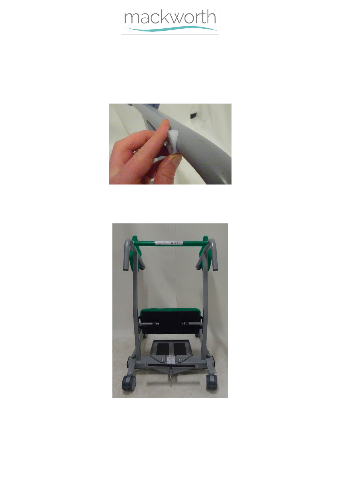
Ensure Crossbar is aligned correctly, with the Labels facing
Horizontally. Re-adjust accordingly.
Knee Pad:
Inspect the Knee Pad for damage including cuts and breaks.
Ensure Knee Pad is still secure and has a slight ability of
rotation.
Seat Pads:
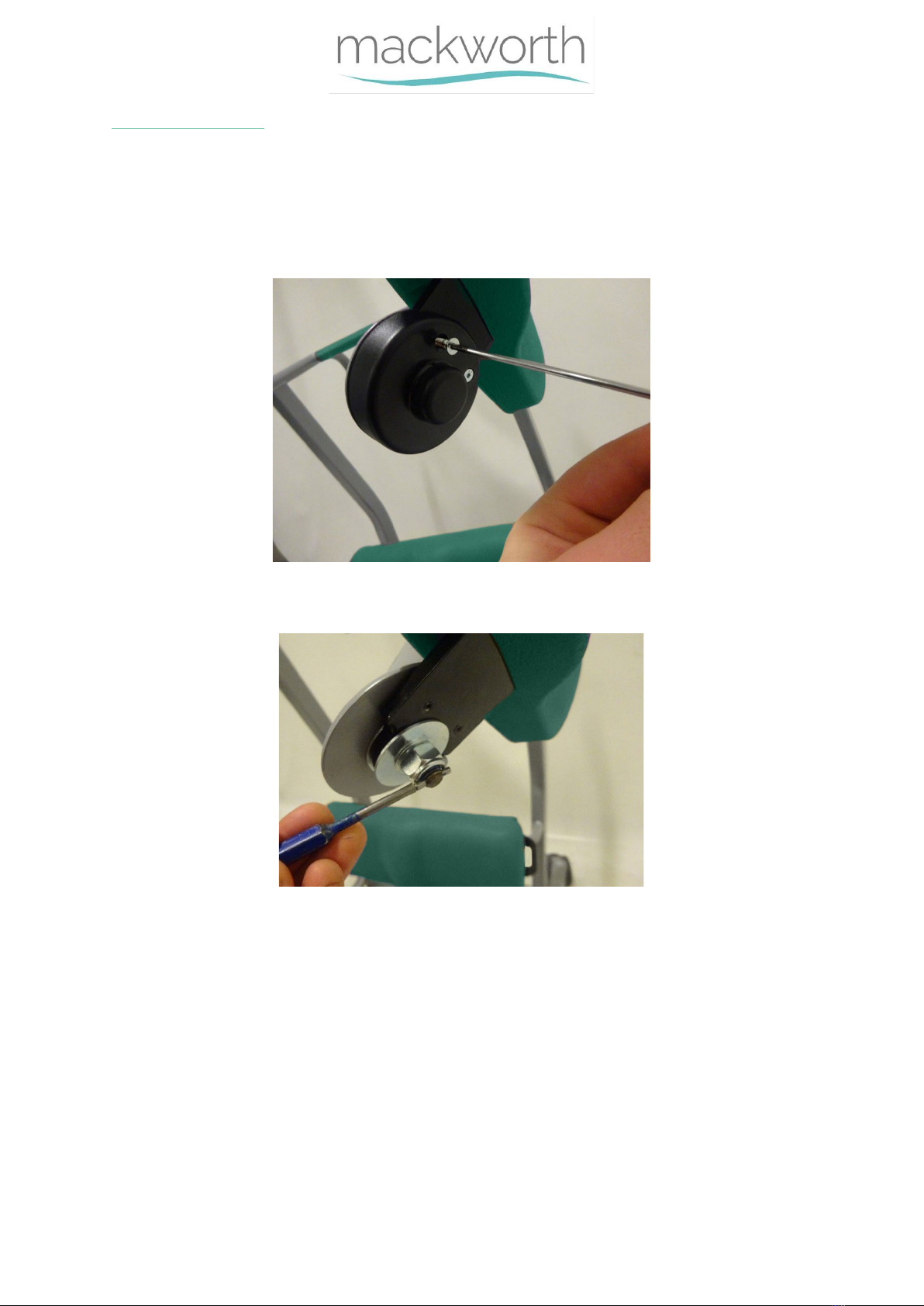
Ensure the seat pads swivel smoothly.
Ensure the seat pads are not damaged, including cuts and
brakes.
Ensure the seat pads align with each other as intended, no
deformation is present.
Foot Tray:
Ensure the Foot Grips are still applied and undamaged.
Inspect the Foot Tray for any permanent deformation or
fatigue.
Ensure no cracks are present and the Foot Tray is attached
correctly.
Ensure Foot Tray is fitted correctly.

995562 – Revision A Page 5of 21
Manual Leg Opener:
Check Leg Opener device, opens and closes the Legs as
intended, ensure it does not require excessive force to
perform this action.
Legs:
Ensure Legs are perpendicular to the Base when closed.
Brakes:
Ensure the Brakes function when activated
Ensure the Transfer Aid can move freely when the Brakes are
deactivated. (Ensure they aren’t rubbing on the Wheels)
Castors and Wheels
Examine the products Wheels and Castors for signs of damage
or wear, ensure they run freely and are not cracked.
Check to see all castors are flat on the floor and Transfer Aid
is stable.
Ensure the product is able to rotate freely with ease.
4.0 – Tools, Equipment and Lubricants Required for
Servicing
When carrying out work on the Mackworth TA400 Transfer Aid you will require the following:
Tools Required
15mm Spanner
17mm Spanner
17mm Ratchet Spanner
2.5mm Allen Key
3mm Allen Key
5mm Allen Key x2
6mm Allen Key
Parallel Pin Punch
Circlip Pliers
Small Nylon Hammer
Equipment Required
Marker Pen
Cloth
Lint Free Cloth
Set Square
Sundries Required
Loctite 243
Equipment Required
Service Manual
User Manual
Spare Parts Manual

995562 – Revision A Page 6of 21
5.0 – Decommissioning
When the Transfer Aid has completed its life cycle and can no longer perform to its intended use
safely, the Transfer Aid must be decommissioned by an approved Service Engineer. The following
specifies the importance of correct disposal procedure including local laws and being
environmentally friendly.
Please observe the local laws on recycling and respect the current laws for disposal within the
community the device is being used within. If there is any uncertainty of the below guidelines,
contact your local authorities to determine the proper method of disposal of potentially
biohazardous parts and accessories.
The relevant components utilised in the manufacture of the device that can be recycled at the end of
the device life are:
Fully recyclables:
Consideration when Recycling:
Steel frame (Frame, Crossbar, Legs)
Seat Pads
Castors
Knee Pad
Initial packaging of the device (cardboard)
Metallic fixing – screws etc.
6.0 – Spare Parts List
For the full list of Spare Parts available for this product. Please refer to the latest revision of the
Spare Parts Manual.
Document Number: 992562.
The Spare Parts Manual can be located on the Mackworth Website: http://mackworthusa.com

995562 – Revision A Page 7of 21
7.0 – Servicing – Removal and Replacement
This section will cover the details of how to remove, refit and replace all serviceable parts to the
Transfer Aid. The step by step process is to be followed in sequence to perform a successful service
on the Product. Unless stated otherwise, all images refer to a Mackworth TA400.
7.1 – Crossbar
This section will instruct the correct procedure on how to remove and replace the TA180
Crossbar.
Removal
Step 1 – Using a 15mm Spanner, remove the Bolt from the Frame to release the Crossbar as
shown, do this for both sides of the Frame.
Step 2 – Remove the Crossbar from the Frame, ensure not to lose the white saddle washers
from either end.

995562 – Revision A Page 8of 21
Refitting / Replacement
Step 3 – Refitting is a reversal of the removal process noting the following points:
A) When aligning the Crossbar, ensure to align the white saddle washers correctly as
shown.
B) Position the Crossbar to ensure correct orientation of the Crossbar, with the Labels
facing horizontally.
C) Apply Loctite 243 to the Crossbar securing bolts.

995562 – Revision A Page 9of 21
7.2 – Seat Pad
In this section it will explain the correct procedure on removing and refitting the Seat Pad.
Removal
Step 1 – Remove the Finger Trap Guard using a 2.5mm Allen Key on the two screws shown.
Step 2 – Using a small Hammer and a Parallel Pin Punch, remove the small retaining pin
which secures the Nut in place.
Step 3 – Using a 17mm Spanner, remove the nut from position.

995562 – Revision A Page 10 of 21
Step 4 – In the following order the parts can be removed – Small Washer, Large Washer,
Seat Pad and Large Washer.
Refitting / Replacement
Step 5 - Refitting is a reversal of the removal process noting the following points:
A) Ensure that the step 4 is followed with the parts attached in the correct order.
B) Ensure that the Seat Pad is attached in the correct orientation, where the Pad faces
inward towards the Frame, and that it sits in position as shown.

995562 – Revision A Page 11 of 21
7.3 – Knee Pad
In this section it will explain the correct procedure on removing and reinstalling the Knee
Pad for servicing procedures or replacement.
Removal
Step 1 – Remove the Bolts and washers on both sides using a 6mm Allen Key.
Step 2 – Knee Pad will be released and can be removed.
Step 3 – (Where applicable) – Use a 3mm Allen Key to remove the Grub screw and slide off
the Knee Pad holder.
Refitting / Replacement
Step 4 - Refitting is a reversal of the removal process noting the following points:
A) Ensure that the Knee Pad is fitted in the correct orientation as shown in the image.

995562 – Revision A Page 12 of 21
B) When fitting the Bolt, ensure the washers are in order as shown below – Bolt,
washer, nylon washer, knee pad, nylon washer.
C) (Where applicable) – Align the Knee Pad holder as shown in the image in step 3.
D) Apply Loctite 243 to both Bolts that secure the Knee Pad
7.4 – Foot Tray
In this section it will explain the correct procedure on removing and reinstalling the Foot
Tray for servicing procedures or replacement.
Removal
Step 1 – Using both hands, raise the Foot Tray from the Foot Tray Pins to remove.
Step 2 – (Where applicable) – If there is a Circlip fitted, use Circlip Pliers to remove the
Circlip and washer each pin, and then refer to Step 1.
Refitting / Replacement
Step 3 - Refitting is a reversal of the removal process.

995562 – Revision A Page 13 of 21
7.5 – Front Castor
In this section it will explain the correct procedure on removing and reinstalling the Front
Castors for servicing procedures or replacement. The below instructions are relevant to both
to both Front Castors.
Removal
Step 1 – Remove the Foot Tray from the product. (Refer to section 7.4)
Step 2 - Place the Transfer Aid on its side for easier service.
Step 3 – Using a 17mm Ratchet Spanner and a 6mm Allen Key, remove the nut and bolt from
the castor to release.
Step 4 – Remove the Castor from the bolt.
Refitting / Replacement
Step 5- Refitting is a reversal of the removal process noting the following points:
A) Ensure that the bolt is fully secured once tightened while ensuring the Castor is able
to spin freely.
B) Ensure the Washer is fitted on the underside of the Castor.

995562 – Revision A Page 14 of 21
7.6 – Rear Castors
Within this section it will explain the correct procedure on removing and reinstalling the
Rear Castors for servicing procedures or replacement. The below instructions are relevant to
all four Castors.
Removal
Step 1 – Remove the Foot Tray from the product. (Refer to section 7.4)
Step 2 - Place the Transfer Aid on its side for easier service.
Step 3 – Using a 17mm Ratchet Spanner and a 6mm Allen Key, remove the nut and bolt from
the castor to release.
Step 4 – Remove the Castor from the bolt.
Refitting / Replacement
Step 5 - Refitting is a reversal of the removal process noting the following point:
A) Ensure that the bolt is fully secured once tightened while ensuring the Castor is able
to spin freely.
B) Ensure the Washer is fitted on the underside of the Castor.

995562 – Revision A Page 15 of 21
7.7 – Manual Leg Rods
Within this section it will explain the correct procedure on removing and reinstalling the
Manual Leg Rods for servicing procedures or replacement.
Removal
Step 1 – Remove the Foot Tray from the product. (Refer to section 7.4)
Step 2 - Place the Transfer Aid on its side for easier service.
Step 3 – Remove the Four Bolts circled in the image below using a 6mm Allen Key.
Step 4 – The Leg Rods can be removed from the product.
Refitting / Replacement
Step 5 - Refitting is a reversal of the removal process noting the following points.
A) Ensure the Bolts are tight and that the Rods are secure, Check functionality of the
Rods by using the Manual Leg Opener. Ensure the Legs fully open and close
smoothly.
B) Use an adequate amount of Loctite 243 on the four Bolts when securing.

995562 – Revision A Page 16 of 21
7.8 – Manual Leg Opener
Within this section it will explain the correct procedure on removing and reinstalling the
Manual Leg Rods for servicing procedures or replacement.
Removal
Step 1 – Remove the Foot Tray from the product. (Refer to section 7.4)
Step 2 - Place the Transfer Aid on its side for easier service.
Step 3 – Remove the Manual Leg Rods from the Base. (Refer to section 7.7)
Step 4 – Remove the Bolt from the Leg Pivot Plate as shown below using a 6mm Allen Key.
Step 5 – Once the Bolt is removed, the Leg Leaver Plate Pin can be removed.
Step 6 – Using a 5mm Allen Key, remove the Bolt and washer shown to release the Leg
Leaver Plate.

995562 – Revision A Page 17 of 21
Step 7 – Ensure the shoulder washer on the inner side of the leaver plate is not lost and
remains inserted into the Leaver Plate.
Step 8 – To remove the Leg Pivot Plate, remove the bolt fixing it in place using an 8mm Allen
Key.
Step 9 – The image below shows the order of the spacers and washer in front of the Pivot
Plate – Spacer, Black Washer, and White Washer.
Step 10 – Remove the Leg Pivot Plate along with the White Washer underneath.

995562 – Revision A Page 18 of 21
Refitting / Replacement
Step 11 - Refitting is a reversal of the removal process noting the following points.
A) Align the Pivot Plate as shown, with the longer end facing towards the rear castors.
B) Ensure the short end fits between the two circled stops on the framework.
C) Ensure the Order is correct for the following parts when fitting the Pivot Plate. White
Washer, Leg Pivot Plate, White Washer, Black Washer, Spacer and Bolt
D) When attaching the Leaver Plate, ensure the shoulder washer is fitted.
E) All three Bolts require an adequate amount of Loctite 243 applied before fitting.

995562 – Revision A Page 19 of 21
7.8 – Leg
Within this section it will explain the correct procedure on removing and reinstalling the Legs
for servicing procedures or replacement. The below information is relevant to both legs on
the product.
Removal
Step 1 – Remove the Foot Tray from the product. (Refer to section 7.4)
Step 2 - Place the Transfer Aid on its side for easier service.
Step 3 – Remove the Manual Leg Rods from the Base. (Refer to section 7.7)
Step 4 – Using two 5mm Allen Keys, remove one of the screws from the Leg Pivot Pin
Step 5 – Remove the Leg Pivot Pin to release the Leg from the Base.
Step 6 – Remove the Leg from the Base.

995562 – Revision A Page 20 of 21
Refitting / Replacement
Step 7 - Refitting is a reversal of the removal process noting the following points.
A) Ensure the Leg is attached the correct orientation, with the castor facing the ground.
B) Apply Loctite 243 to the removed screw when refitting.
7.9 – Frame
Within this section it will explain the correct procedure on removing and reinstalling the Legs
for servicing procedures or replacement. The below information is relevant to both legs on
the product.
Removal
Step 1 – Remove the Crossbar from the Product. (Refer to section 8.1)
Step 2 – Remove the Seat Pads from the Product. (Refer to section 8.2)
Step 3 – Remove the Knee Pad from the Product. (Refer to section 8.3)
Step 4 – Remove the Foot Tray from the Product. (Refer to section 8.4)
Step 5 – Remove the Front Castors from the Product. (Refer to section 8.5)
Step 6 – Remove the Rear Castors from the Product. (Refer to section 8.6)
Step 7 – Remove the Manual Leg Rods from the Product (Refer to section 8.7)
Step 8 – Remove the Manual Leg Opener from the Product. (Refer to section 8.8)
Step 9 – Remove the Legs from the Product. (Refer to section 8.9)
Refitting / Replacement
Step 10 - Refitting is a reversal of the removal process.
Other manuals for TA400
1
Table of contents
Other Mackworth Mobility Aid manuals

Mackworth
Mackworth TA180 User manual

Mackworth
Mackworth M400 User manual

Mackworth
Mackworth SA400 User manual

Mackworth
Mackworth SA180 User manual

Mackworth
Mackworth 540100 User manual

Mackworth
Mackworth SA180 User manual

Mackworth
Mackworth 999029 User manual

Mackworth
Mackworth TA400 User manual

Mackworth
Mackworth M Series User manual

Mackworth
Mackworth M180 User manual
Popular Mobility Aid manuals by other brands

Schuchmann
Schuchmann till Instructions for use

decon
decon Netti 4U Assembly instructions

EasyStand
EasyStand Bantam Medium Perfect Fit Guide

Nightingale
Nightingale ProAxis Plus Instructions for use

iWALKFree
iWALKFree iWALK 2.0 user guide

Invacare
Invacare Tracer SX5 Recliner Assembly and installation instructions