manuals.online logo
Brands
  1. Home
  2. •
  3. Brands
  4. •
  5. MadgeTech
  6. •
  7. Data Logger
  8. •
  9. MadgeTech Bridge120 User manual

MadgeTech Bridge120 User manual

This manual suits for next models

4

Other MadgeTech Data Logger manuals

MadgeTech ThermoVault Specification sheet

MadgeTech

MadgeTech ThermoVault Specification sheet

MadgeTech SHOCK300 Specification sheet

MadgeTech

MadgeTech SHOCK300 Specification sheet

MadgeTech HiTemp1400 User manual

MadgeTech

MadgeTech HiTemp1400 User manual

MadgeTech Volt101A User manual

MadgeTech

MadgeTech Volt101A User manual

MadgeTech RTDTemp2000 User manual

MadgeTech

MadgeTech RTDTemp2000 User manual

MadgeTech EggTemp-RH User manual

MadgeTech

MadgeTech EggTemp-RH User manual

MadgeTech PRHTemp2000 User manual

MadgeTech

MadgeTech PRHTemp2000 User manual

MadgeTech Temp1000 User manual

MadgeTech

MadgeTech Temp1000 User manual

MadgeTech HiTemp140-FPST-36 User manual

MadgeTech

MadgeTech HiTemp140-FPST-36 User manual

MadgeTech RFPulse2000A User manual

MadgeTech

MadgeTech RFPulse2000A User manual

MadgeTech Process101A User manual

MadgeTech

MadgeTech Process101A User manual

MadgeTech RFCurrent2000A Specification sheet

MadgeTech

MadgeTech RFCurrent2000A Specification sheet

MadgeTech Volt101A-30V Specification sheet

MadgeTech

MadgeTech Volt101A-30V Specification sheet

MadgeTech MadgeNET RFTemp2000A Specification sheet

MadgeTech

MadgeTech MadgeNET RFTemp2000A Specification sheet

MadgeTech RTDTemp2000 User manual

MadgeTech

MadgeTech RTDTemp2000 User manual

MadgeTech QuadRTDTempV2 Specification sheet

MadgeTech

MadgeTech QuadRTDTempV2 Specification sheet

MadgeTech HITEMP140-1 Specification sheet

MadgeTech

MadgeTech HITEMP140-1 Specification sheet

MadgeTech Pulse101A Specification sheet

MadgeTech

MadgeTech Pulse101A Specification sheet

MadgeTech HiTemp140 Series Specification sheet

MadgeTech

MadgeTech HiTemp140 Series Specification sheet

MadgeTech Event101A User manual

MadgeTech

MadgeTech Event101A User manual

MadgeTech Shock101-5 User manual

MadgeTech

MadgeTech Shock101-5 User manual

MadgeTech HiTemp140-PT Specification sheet

MadgeTech

MadgeTech HiTemp140-PT Specification sheet

MadgeTech PR2009 Specification sheet

MadgeTech

MadgeTech PR2009 Specification sheet

MadgeTech Bridge120 Series User manual

MadgeTech

MadgeTech Bridge120 Series User manual

Popular Data Logger manuals by other brands

UGCS SkyHub user manual

UGCS

UGCS SkyHub user manual

Avisaro 4.0 Series user manual

Avisaro

Avisaro 4.0 Series user manual

DDB C3 manual

DDB

DDB C3 manual

TESTO 176 instruction manual

TESTO

TESTO 176 instruction manual

HBM SOMAT XR CX22B-R operating manual

HBM

HBM SOMAT XR CX22B-R operating manual

Agtrix 380i manual

Agtrix

Agtrix 380i manual

Beijing ART Tech PCI2320 user manual

Beijing ART Tech

Beijing ART Tech PCI2320 user manual

Athena GET SL1 user manual

Athena

Athena GET SL1 user manual

Motec Systems C185 user manual

Motec Systems

Motec Systems C185 user manual

Beijing ART Tech USB2832 user manual

Beijing ART Tech

Beijing ART Tech USB2832 user manual

HT Italia XL421 user manual

HT Italia

HT Italia XL421 user manual

Racelogic VBOX LapTimer quick start guide

Racelogic

Racelogic VBOX LapTimer quick start guide

Edu-Logger 900-240 Guide

Edu-Logger

Edu-Logger 900-240 Guide

Elma DT173 manual

Elma

Elma DT173 manual

Comet U0121M user guide

Comet

Comet U0121M user guide

pico Technology PT-104 user guide

pico Technology

pico Technology PT-104 user guide

Sensus DIAVASO user manual

Sensus

Sensus DIAVASO user manual

Soil Instruments GTecLink user manual

Soil Instruments

Soil Instruments GTecLink user manual

manuals.online logo
manuals.online logoBrands
  • About & Mission
  • Contact us
  • Privacy Policy
  • Terms and Conditions

Copyright 2025 Manuals.Online. All Rights Reserved.

Bridge120
Red 485
Dark Blue Pantone 289
Light Blue 58% of Pantone 289
Red 485
Dark Blue Pantone 289
Light Blue 58% of Pantone 289
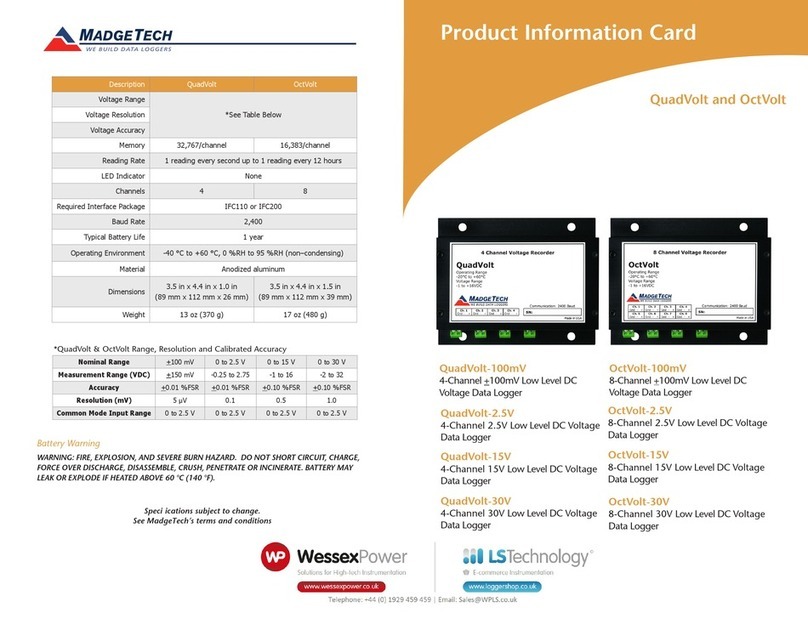
*Bridge120 Range, Resolution and Accuracy
Nominal Range +10mV +25mV +100mV +1000mV
Measurement Range +15mV +37.5mV +120mV +1200mV
Resolution 1µV 2.5µV 5µV 50µV
Accuracy +0.25%FSR +0.10%FSR +0.05%FSR +0.01%FSR
Input Range 0 to 2.5V 0 to 2.5V 0 to 2.5V 0 to 2.5V
Reference Voltage 2.5V 2.5V 2.5V 2.5V
Battery Warning
WARNING: FIRE, EXPLOSION, AND SEVERE BURN HAZARD. DO NOT SHORT CIRCUIT, CHARGE,
FORCE OVER DISCHARGE, DISASSEMBLE, CRUSH, PENETRATE OR INCINERATE. BATTERY MAY
LEAK OR EXPLODE IF HEATED ABOVE 80°C (176°F).
Specifications subject to change.
Bridge120-10
10mV, 20 Hz, Bridge Data Logger
Bridge120-25
25mV, 20 Hz, Bridge Data Logger
Bridge120-100
100mV, 20 Hz, Bridge Data Logger
Bridge120-1000
1000mV, 20 Hz, Bridge Data Logger
Part Number Bridge120
Range
See Table Below*Resolution
Accuracy
Memory 32,767
Sample Rate 20Hz to 12 hours
Units V, mV,
µ
V, Engineering Units specied through software
Required Interface Package IFC110 or IFC200
Baud rate 57,600
Typical Battery Life 25 days
Operating Environment –40°C to +80°C (-40°F to 176°F),
0%RH to 95%RH (non-condensing)
Material ABS plastic
Dimensions 0.8” x 1.7” x 2.7” (20mm x 43mm x 69mm)
Approvals CE Pending
Product Information Card
www. .com information@itm.com1.800.561.8187
Product Notes
The Bridge120 data logger is designed to interface with and measure strain gauges and load
cells. The device provides an excitation voltage of 2.5V’s and is available in the following
millivolt input ranges: ±10mV, ±25mV, ±100mV, ±1000mV. The Bridge120 features a
sampling rate of up to 20Hz.
LEDs
Once started, the LED will flash at the selected reading rate to indicate the device is running.
Configuring the Data Logger
Voltage Divider Configuration
The Voltage Divider configuration is a frequently used setup to measure bridge strain.
1. Jumper between POWER and REF+
2. Place a 12k resistor between REF+ and REF-
3. Jumper between REF- and IN+
4. Place the strain gage between IN+ and IN-
5. Jumper between IN- and GROUND
Conversions
To convert the Voltage values into Ohms, use the following formula:
Example: The MadgeTech software reports a voltage of 20mV in the circuit described above.
The strain gage resistance is therefore:
The resistor Ro between REF+ and REF- and the strain gage value form the mV reference
(mVref). This may be expressed as:
The Bridge120-25 has a resolution of about 2µV. If the resistance of the strain gage
changes by +.1, the device would measure a change of approximately +20µV. Conversely,
this voltage resolution translates in Ohms to approximately:
Note: The maximum voltage must be kept within the specified input range. See data sheet for details.
Installation Guide
Installing the Interface cable
- IFC200
Insert the device into a USB port. The drivers will install automatically.
- IFC110
Plug the serial cable into the port and verify it is secure.
Installing the software
Insert the Software USB into an open USB port. If the autorun does not appear, locate the
drive on the computer and double click on Autorun.exe. Follow the onscreen instructions.
Connecting the data logger
- Once the software is installed and running, plug the interface cable into the data logger.
- Click the Communication Menu, then Auto Configure Port.
- After a moment, a box will appear stating a device has been found.
- Click OK. The Device Status box will appear. Click OK.
- At this point, communications have been configured for your logger. These settings can
be found under the Communication Menu.
Device Operation
Starting the data logger
- Click Device Menu then Start Device.
- Choose the desired start method.
- Choose the start parameters by selecting a Reading Rate suitable for your application.
- Enter in any other desired parameters and click Start.
- A box will appear stating the data logger has been started. Click OK.
- Disconnect the data logger from the interface cable and place it in the environment.
Note: The device will stop recording data when the end of memory is reached or the device is stopped. At this
point the device cannot be restarted until it has been re-armed by the computer.
Downloading data from a data logger
- Connect the data logger to the interface cable.
- Click the Device Menu then Read Device Data. This will offload recorded data onto the PC.
Device Maintenance
Battery Replacement
Materials: Small Phillips Head Screwdriver and a Replacement Battery (LTC-7PN)
- Puncture the center of the back label with the screw driver and unscrew the enclosure.
- Remove the battery by pulling it perpendicular to the circuit board.
- Insert the new battery into the terminals and verify it is secure.
- Screw the enclosure back together securely.
Note: Be sure not to over tighten the screws or strip the threads.
Recalibration
Bridge120 standard calibration values:
Product Quick Reference Card
POWER
REF +
REF -
IN +
IN -
GROUND
Ro=12kΩ
Strain Gauge Rsg
Bridge120
Logger Voltage 10mV 25mV 100mV 1000mV
Strain (V) 0V and
9-10mV
0V and
22.5-25mV
0V and
90-100mV
0V and
900-1000mV
www. .com information@itm.com1.800.561.8187