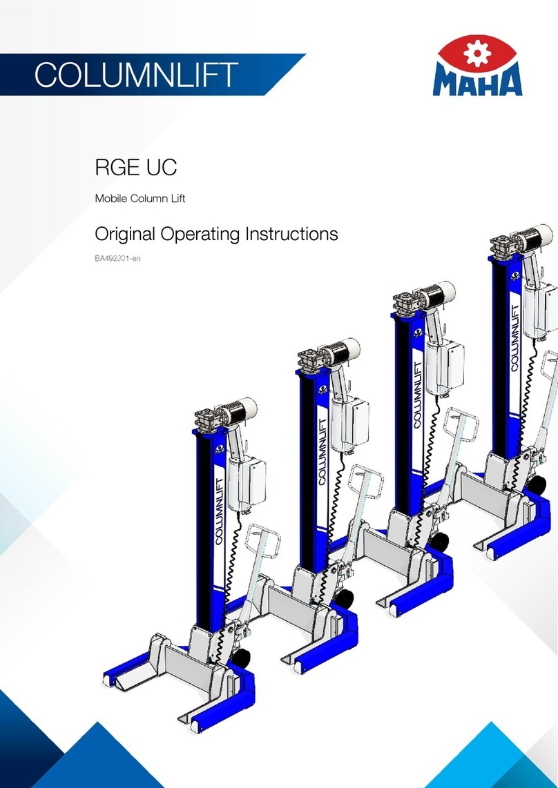
MAHA RGE UNI TRAM User manual

Fehler! Verwenden Sie die Registerkarte 'Start', um Name dem Text zuzuweisen, der hier angezeigt werden soll.Fehler! Verwenden Sie
die Registerkarte 'Start', um Name dem Text zuzuweisen, der hier angezeigt werden soll.Fehler! Verwenden Sie die Registerkarte
'Start', um Name dem Text zuzuweisen, der hier angezeigt werden soll.
RGE UNI TRAM
Mobile Column Lift
Original Operating Instructions
BA491701-en
Pos: 1 /-----Fo rmat-----/MANUE LLER UMBRUCH Seitenumbruch@ 0\mod_1134403577687_0.do cx @ 1277 @ @ 1

2
BA491701-en
Pos: 2 /-----Fo rmat-----/Inhaltsve rzeichnis- 3 Ebenen @ 5\mod_116886744 1046_75.do cx @ 729 20 @ @ 1
Contents
1Safety ......................................................................................................................5
1.1 Introduction......................................................................................................................................... 5
1.2 Symbols .............................................................................................................................................. 5
1.3 Intended Use....................................................................................................................................... 5
1.4 Inappropriate Use................................................................................................................................ 5
1.5 Safety Instructions for Commissioning................................................................................................. 5
1.6 Safety Instructions for Operation ......................................................................................................... 5
1.7 Safety Instructions for Servicing........................................................................................................... 6
1.8 What to Do in the Event of Defects or Malfunctions............................................................................. 6
1.9 What to Do in the Event of an Accident............................................................................................... 6
1.10 Safety Features ................................................................................................................................... 7
1.10.1 Locking Device.................................................................................................................................... 7
1.10.2 Braking Motor ..................................................................................................................................... 7
1.10.3 Phase Sequence Relay........................................................................................................................ 7
1.10.4 Thermal Overload Protection............................................................................................................... 7
1.10.5 Safety Shutdown after Motor Overload................................................................................................ 7
1.10.6 Warning and Information Labels .......................................................................................................... 7
2Description...............................................................................................................8
2.1 General Information............................................................................................................................. 8
2.2 Noise Emission.................................................................................................................................... 8
2.3 Specifications...................................................................................................................................... 8
2.4 Sample Nameplate.............................................................................................................................. 9
3Installation..............................................................................................................10
4Operation...............................................................................................................11
4.1 Requirements on the Operator .......................................................................................................... 11
4.2 Handling / Moving the Columns ........................................................................................................ 11
4.3 Lift Positioning................................................................................................................................... 12
4.4 Controls ............................................................................................................................................ 14
4.5 Main Switch ...................................................................................................................................... 15
4.6 Emergency Stop................................................................................................................................ 15
4.7 Operating Modes .............................................................................................................................. 15
4.7.1 Automatic Mode................................................................................................................................ 15
4.7.2 Single Mode ...................................................................................................................................... 16
4.7.3 Group Mode...................................................................................................................................... 17
4.7.4 Cable Remote Control....................................................................................................................... 17
4.8 Emergency-down Function, Mechanical............................................................................................ 18
4.9 Operation with more than 6 Columns................................................................................................ 19
4.10 Load Acknowledge Switch (Optional) ................................................................................................ 20
5Maintenance ..........................................................................................................21
3
BA491701-en
5.1 Annual Inspection.............................................................................................................................. 21
5.2 Care Instructions ............................................................................................................................... 21
5.3 Spare Parts ....................................................................................................................................... 21
5.4 Maintenance by the Operator............................................................................................................ 22
5.4.1 Recirculating Ball Nut ........................................................................................................................ 22
5.4.2 Options ............................................................................................................................................. 23
5.5 Setting the Hydraulic Jack................................................................................................................. 24
5.6 Display Codes ................................................................................................................................... 25
6Service Lifetime......................................................................................................27
7Dismantling ............................................................................................................27
8Disposal.................................................................................................................27
9Contents of the Declaration of Conformity ..............................................................27
10 Company Information.............................................................................................28
Pos: 3 /-----Fo rmat-----/MANUE LLER UMBRUCH Seitenumbruch@ 0\mod_1134403577687_0.do cx@ 1277 @ @ 1

4
BA491701-en
Pos: 4 /-----Fo rmat-----/MANUE LLER UMBRUCH Seitenumbruch@ 0\mod_1134403577687_0.do cx @ 1277 @ @ 1

5
BA491701-en
Pos: 5/Technische Dokumentation/AlleGeräte/Überschriften/Überschriften1/S/Überschrift1: S icherheit @ 6\mod_11744823999 06_75.docx @ 76962@ 1 @ 1
1
Safety
Pos: 6 /Technische Dokumentation/Alle Geräte/Überschriften/Überschriften 1.1/E/Überschrift 1.1: Einführung @ 6\mod_1174482219 062_75.docx @ 7679 3@ 2 @ 1
1.1
Introduction
Pos: 7 /Technische Dokumentation/Alle Geräte/Inhalte/Sicherheit/Inhalt: Einführung Sicherheit @ 6\mod_1175609639 562_75.docx @ 87528 @ @ 1
Thoroughly read this manual before operating the equipment and comply with the instructions.
Always display the manual in a conspicuous location.
Personal injury and property damage incurred due to non-compliance with these safety
instructions are not covered by the product liability regulations.
Pos: 8/Technische Dokumentation/AlleGeräte/Überschriften/Überschriften1.1/S/Über schrift 1.1: Sy mbole @ 6\mod_1174482270875_75. docx @ 76865 @ 2 @ 1
1.2
Symbols
Pos: 9 /Technische Dokumentation/Alle Geräte/Inhalte/Sicherheit/Inhalt: Symbole Sicherheit @ 14\mod_1239866667866_ 75.doc x @ 361518 @ @ 1
Important safety instructions. Failure to comply with instructions could result in personal injury or
property damage.
Important information.
Pos: 10 /TechnischeDokumentation/Alle Geräte/Überschriften/Überschriften 1.1/B/Überschrift 1.1: BestimmungsgemäßerGebrauch @ 6\mod_1176734022203_75. docx @ 88746 @ 2@ 1
1.3
Intended Use
Pos: 11 /Technische Dokumentation/Hebetechnik/49 Radgreifer-Hebebühnen/0001 Radgreifer-Hebebühnen Alle/Inhalte/Inhalt: Bestimmungsgemäßer Gebrauch RG-HBZ Schiene @ 22\mod_129 4930190394_75.doc x@ 9 62205 @ @ 1
•This lift is to be used exclusively for the safe lifting of rail vehicles. Observe the rated load
capacity.
•The lift shall not be modified without the express written consent of the manufacturer. In case of
non-compliance the declaration of conformity becomes void.
Pos: 12 /TechnischeDokumentation/Alle Geräte/Überschriften/Überschriften 1.1/B/Überschrift 1.1: BestimmungswidrigerGebrauch @ 18\mod_1255530265027_ 75.docx @ 471571 @ 2 @ 1
1.4
Inappropriate Use
Pos: 13 /Technische Dokumentation/Hebetechnik/00 HBZ Alle/Inhalte/Inhalt: Bestimmungswidriger Gebrauch HBZ@ 19\mod_1267188702628_75.do cx @ 794843 @ @ 1
Any use other than described is inappropriate, for example:
•Climbing on the lift supports
•Transporting persons on the lift supports
•Usage as mobile work platform or for other lifting operations
Pos: 14 /Technische Dokumentation/Alle Geräte/Überschriften/Überschriften1.1/S/Überschrift1.1: Sicherheitsvorschriften fürdie Inbetriebnahme@ 6\mod_1174482269 156_75.docx @ 76838 @ 2 @ 1
1.5
Safety Instructions for Commissioning
Pos: 15 /Technische Dokumentation/Hebetechnik/49 Radgreifer-Hebebühnen/0001 Rad greifer-Hebebühnen Alle/Inhalte/Inhalt: Sicherheitsvorschriften für die I nbetriebnahme RG-HBZ @ 6\mo d_1178094134921_75. docx @ 90757 @ @ 1
•Use the lift on a hard, level surface only.
•The standard lift version may not be installed and commissioned in the vicinity of explosives or
flammable liquids.
Pos: 16 /Technische Dokumentation/Alle Geräte/Überschriften/Überschriften 1.1/S/Überschrift 1.1: Sicherheitsvorschriften für den Betrieb @ 6\mod_117448226 8953_75.docx @ 76826 @ 2@ 1
1.6
Safety Instructions for Operation
Pos: 17 /Technische Dokumentation/Hebetechnik/49 Radgreifer-Hebebühnen/0001 Rad greifer-Hebebühnen Alle/Inhalte/Inhalt: Sicherheitsvorschriften für den Be trieb RG-HBZ @ 6\mod_11780946579 21_75.docx @ 9 0770 @ @ 1
•Read the detailed operating manual.
•Lift operation by trained personnel over 18 years only.
•Do not exceed the rated load capacity per column as indicated on the lift nameplate.

6
BA491701-en
•Ensure an unobstructed movement of lift and vehicle.
•After raising the vehicle briefly, stop and check the lift supports for secure contact with the
vehicle.
•Closely watch lift and vehicle during raising and lowering cycles.
•The working area which cannot be overviewed by the operator should be monitored by a
second person.
•When operating the lift in single or group mode, make sure the vehicle is not tilted.
•Do not allow anyone to stay in lift area during raising and lowering cycles.
•Do not allow anyone to climb on lift or inside raised vehicle.
•Keep lift and vehicle free of tools and parts.
•When using the lift outdoors, lower the vehicle and stop operation when the wind velocity
exceeds 6 m/s.
•Push the support forks completely under the wheels or lift points of the vehicle to be raised.
•Do not drive over or pinch electrical cables.
Pos: 18 /Technische Dokumentation/Alle Geräte/Überschriften/Überschriften 1.1/S/Überschrift 1.1: Sicherheitsvorschriften für Ser vicearbeiten@ 6\mod_1174482270640_ 75.docx @ 76850 @ 2@ 1
1.7
Safety Instructions for Servicing
Pos: 19 /Technische Dokumentation/Hebetechnik/49 Radgreifer-Hebebühnen/0001 Radgreifer-Hebebühnen Alle/Inhalte/Inhalt: Sicherheitsvorschriften für Servicearbeiten RG -HBZ @ 6\mod_ 1178095227937_75. docx @ 9079 3 @ @ 1
•Service work may be done by authorized service technicians only.
•Turn off and padlock the main switch before doing any repair, maintenance or setup work.
•Disconnect the mains plug before opening the control box.
•Work on the electrical equipment may be done by service technicians or certified electricians
only.
•Ensure that ecologically harmful substances are disposed of only in accordance with the
appropriate regulations.
•Do not use high pressure or steam jet cleaners. Use of caustic cleaning agents may damage
the lift.
•Do not replace or override the lift safety devices.
Pos: 20 /Technische Dokumentation/Alle Geräte/Überschriften/Überschriften 1.1/V/Überschrift 1.1: Verhalten im S törfall @ 6\mod_117809700 8375_75.doc x @ 90829 @ 2@ 1
1.8
What to Do in the Event of Defects or Malfunctions
Pos: 21 /Technische Dokumentation/Hebetechnik/00 HBZ Alle/Inhalte/Inhalt: Verhalten im Störfall HBZ @ 19\mod_126717709549 4_75.docx @ 79 4570 @ @ 1
•In case of defects or malfunctions such as uncontrolled lift movement or deformation of the
superstructure, support or lower the lift immediately.
•Turn off the main switch and secure it against unauthorized usage. Contact service.
Pos: 22 /Technische Dokumentation/Alle Geräte/Überschriften/Überschriften 1.1/V/Überschrift 1.1: Verhalten bei Unfällen @ 19 \mo d_1267177245337_75.d ocx @ 794600 @ 2 @ 1
1.9
What to Do in the Event of an Accident
Pos: 23 /TechnischeDokumentation/Alle Geräte/Inhalte/Sicherheit/Inhalt: Verhalten bei Unfällen@ 34\mod_13811288 04654_75.do cx @ 1837123 @ @ 1
•The injured person is to be removed from the danger area. Find out where dressing and
bandages are kept. Seek first-aid.
•Provide first-aid (stop bleeding, immobilise injured limbs), report the accident and seal off the
accident site.
•Immediately report any accident to your supervisor. Make sure a record is kept of every
occasion first-aid is provided, e.g. in an accident book.
•Remain calm and answer any questions that may arise.
Pos: 24 /-----Fo rmat-----/MA NUELLER UMBRUCH Seitenumbruch @ 0\mod_113440357768 7_0.docx @ 1277 @ @ 1

7
BA491701-en
Pos: 25 /Technische Dokumentation/Alle Geräte/Überschriften/Überschriften 1.1/S/Überschrift 1.1: Sicherheitseinrichtungen @ 6\mod_ 1174483324765_75.doc x @ 77103 @ 2 @ 1
1.10
Safety Features
Pos: 26 /Technische Dokumentation/Hebetechnik/49 Radgreifer-Hebebühnen/0001 Radg reifer-Hebebühnen Alle/Inhalte/Inhalt: Sicherheitseinrichtungen RG-HBZ @ 17\mo d_1250235608088_75. docx @ 4279 93 @ 333333 @ 1
1.10.1
Locking Device
The locking device serves to prevent inadvertent lowering motions caused by gear,
load nut or lifting screw failure. The carriage is blocked by safety wedge (1) and
counterwedge (2).
1.10.2
Braking Motor
The motors are equipped with AC spring pressure brakes. Once the motors
are switched off, the brakes prevent any further movements.
1.10.3
Phase Sequence Relay
The phase sequence relay in the power supply unit ensures safe and
independent operation.
1.10.4
Thermal Overload Protection
Overload protection via electronically monitored thermoswitches.
1.10.5
Safety Shutdown after Motor Overload
The motor load is permanently monitored by the control PCB. If an overload of
≥15 %
occurs, the
system will switch off automatically. In this case the lift cannot be raised any more, but it can be
normally lowered to bottom position.
1.10.6
Warning and Information Labels
Do not change or remove the warning and information labels. Order replacement for defective
labels.
Pos: 27 /-----Fo rmat-----/MA NUELLER UMBRUCH Seitenumbruch @ 0\mod_113440357768 7_0.docx @ 1277 @ @ 1

8
BA491701-en
Pos: 28 /Technische Dokumentation/AlleGe räte/Überschriften/Überschriften1/B/Überschrift 1: Beschreibung @ 6\mod_11744822714 53_75.docx @ 76889 @ 1 @ 1
2
Description
Pos: 29 /TechnischeDokumentation/Alle Geräte/Überschriften/Überschriften 1.1/A/Überschrift 1.1: Allgemeines @ 6\mod_1182865005781_ 75.docx @ 9 7736 @ 2 @ 1
2.1
General Information
Pos: 30 /Technische Dokumentation/Hebetechnik/49 Radgreifer-Hebebühnen/1701 RGEUNI TRAM/BA/Inhalt:4917 Beschreibung Allgemeines @ 24\mod_131252889 4161_75.docx @ 1027060 @ @ 1
The mobile column lifts of the RGE series are produced as wheel engaging or universal lifts.
Depending on the version, the lift system consists of 2 or 4 columns and can be expanded to 6
columns in the standard version.
The lift can be expanded up to 12 columns when using a special power supply unit.
All components are easily accessible under the lifted vehicle due to a generous maximum lifting
height of 1750 mm. An extended lifting height of 2400 mm is optionally available.
The lift is a mobile unit whereby the columns can be substituted with stands when vehicles are to
be worked on for a longer period of time. The lifting columns are free to be used on other vehicles.
Pos: 31 /TechnischeDokumentation/Alle Geräte/Überschriften/Überschriften 1.1/L/Überschrift 1.1: Lärmemission@ 13\mod_1236767272078 _75.docx @ 354579 @ 2@ 1
2.2
Noise Emission
Pos: 32 /Technische Dokumentation/Hebetechnik/00 HBZAlle/Inha lte/Inhalt:Schalldruckpegel < 70 dB(A) @ 14\mod_ 1241593887290_75.do cx @ 371013 @ @ 1
The sound pressure level is lower than 70 dB(A) in the working area of the operator.
Pos: 33 /Technische Dokumentation/Alle Geräte/Überschriften/Überschriften 1.1/T/Überschrift 1.1: Technische Daten @ 7\mod_1184075526343_ 75.docx @ 9 9711 @ 2 @ 1
2.3
Specifications
Pos: 34 /Technische Dokumentation/Hebetechnik/49 Radgreifer-Hebebühnen/1701 RGEUNI TRAM/BA/Inhalt:4917 Technische Da ten@ 24\mod_1312529058363_75.do cx@ 102709 0@ @ 1
Load capacity per column 7500 kg
Lifting height (standard) 1750 mm
Raising/Lowering time * 113 s
Raising speed 0.92 m/min
Motor power 1.5 kW
System of protection IP 54
Supply voltage 3~ 380/220 V; 50 Hz
Net weight per column w/o support * 452 kg
Surface load 0.5 N/mm2
* Applies to standard lifting height of 1750 mm. Raising/Lowering time and Net weight differ from
the above figures when lift is equipped with special lifting height.
Pos: 35 /Technische Dokumentation/Hebetechnik/00 HBZ Alle/Inhalte/Info!/Inhalt: Info - BetriebswarmerZustand/ Techn. Änderu ngen HBZ @ 6\mod_1177427042703_75. docx @ 9 0160 @ @ 1
The properties indicated apply to lifts running at operating temperature.
Specifications are subject to change without notice.
Pos: 36 /-----Fo rmat-----/MA NUELLER UMBRUCH Seitenumbruch @ 0\mod_113440357768 7_0.docx @ 1277 @ @ 1

9
BA491701-en
Pos: 37 /TechnischeDokumentation/Alle Geräte/Überschriften/Überschriften 1.1/T/Überschrift 1.1: Typenschild-Muster @ 11\mod_122762220609 6_75.docx @ 275574 @ 2@ 1
2.4
Sample Nameplate
Pos: 38 /Technische Dokumentation/Hebetechnik/49 Radgreifer-Hebebühnen/1701 RGEUNI TRAM/BA/Inhalt: 4917 Typenschild -Muste r @ 24\mod_1312532491441_ 75.docx @ 1027250 @ @ 1
Mobile Lifting System
Ser. No. / Date of Production: ***
Project: ***
Type: ***
Supply Voltage: ***
Frequency: ***
Rated Current: ***
Fuse Protection: ***
Load Capacity per Column: ***
System of Protection: ***
WEEE-Reg.-No. ***
Pos: 39 /-----Fo rmat-----/MA NUELLER UMBRUCH Seitenumbruch @ 0\mod_113440357768 7_0.docx @ 1277 @ @ 1

10
BA491701-en
Pos: 40 /Technische Dokumentation/Alle Geräte/Überschriften/Überschriften 1/I/Überschrift 1: Installation @ 6\mod_ 1182339865390_75.doc x@ 96509 @ 1 @ 1
3
Installation
Pos: 41 /Technische Dokumentation/Hebetechnik/49 Radgreifer-Hebebühnen/1701 RGEUNI TRAM/BA/Inhalt: 4917 Installation (Bild) @ 19\mod_ 1264751873991_0.docx @ 688897 @ @ 1
Pos: 42 /Technische Dokumentation/Hebetechnik/49 Radgreifer-Hebeb ühnen/1701 RGE UNI TRAM/BA/Inhalt: 4917 Installation ( Text) @ 24\mod_131253410 6864_75.docx @ 1027310 @ @ 1
Example of a simple load support. The design of other supports may differ considerably depending
on the application requirements.
The support must be connected to the carriage using
all
six thread holes. The following fasteners
are needed:
6 Bolts M16x60-12.9 MAHA # 22 0912 16060 1
6 Washers M16 300 HV MAHA # 22 0125 16 2
Tightening torque:
270 Nm
Pos: 43 /-----Fo rmat-----/MA NUELLER UMBRUCH Seitenumbruch @ 0\mod_113440357768 7_0.docx @ 1277 @ @ 1

11
BA491701-en
Pos: 44 /Technische Dokumentation/AlleGe räte/Überschriften/Überschriften1/B/Überschrift 1: Bedienung @ 6\mod_ 1174482271218_75.do cx @ 76877 @ 1@ 1
4
Operation
Pos: 45 /Technische Dokumentation/Papierkorb/Überschriften/Überschrift1.1: Anforderungen an den Bediener @ 18\mod_1255531954990_75. docx @ 471737@ 2 @ 1
4.1
Requirements on the Operator
Pos: 46 /Technische Dokumentation/AlleGe räte/Inhalte/Warnung!/Inhalt: Warnung- Anforderungenan den Bediener@ 19\mod_1267188989 019_75.docx @ 79 4905 @ @ 1
All persons employed in the operation, maintenance, installation, removal and disposal of the plant
must
•be at least 18 years old,
•be trained and instructed in writing,
•have read and understood this manual
•be on record as having been intructed in safety guidelines.
Pos: 47 /TechnischeDokumentation/AlleGeräte/Überschriften/Überschriften1.1/T/Überschrift1.1: Transport/ Verschieben von Hubsäulen @ 12\mod_1231486358029 _75.docx @ 300405 @ 2 @ 1
4.2
Handling / Moving the Columns
Pos: 48 /Technische Dokumentation/Hebetechnik/49 Radgreifer-Hebebühnen/0801 RGE/BA/Inhalt:4908 Transport/Verschieben (Bilder) @ 12\mod_1231486938020_0. docx @ 300505 @ @ 1
Pos: 49 /TechnischeDokumentation/Papierkorb/Hebetechnik/Inhalt: Transport/Verschieben (Text) RGE@ 12\mod_1231486726149 _75.docx @ 300480 @ @ 1
Screw a lifting-eye bolt M16 into the tap hole on the motor plate of the column. Insert a chain or
strap through the ring and lift the column using a hoist or forklift.
Close hydraulic valve by putting valve lever in position 3.
Pump with handle to raise the moving gear. Move column to desired position.
To lower the moving gear, open the hydraulic valve by putting the valve lever in position 1. The
column is ready for operation.
Position 2 is the neutral position.
Pos: 50 /-----Fo rmat-----/MA NUELLER UMBRUCH Seitenumbruch @ 0\mod_113440357768 7_0.docx @ 1277 @ @ 1

12
BA491701-en
Pos: 51 /Technische Dokumentation/Alle Geräte/Überschriften/Überschriften 1.1/A/Überschrift 1.1: Aufstellen der Hebebühne @ 12\mod_1231747750802_ 75.docx @ 301020 @ 2@ 1
4.3
Lift Positioning
Pos: 52 /Technische Dokumentation/Papierkorb/Hebetechnik/Inhalt: Anschlussschema RGE (Text) @ 12\mod_123174855 0599_75.doc x @ 301095 @ @ 1
Connection Diagram
B
Control Unit
1
Connecting Cable
V
Power Supply Unit
2
Dummy Plug
E
Input Terminal
3
Mains Plug
A
Output Terminal
Pos: 53 /Technische Dokumentation/Hebetechnik/49 Radgreifer-Hebebühnen/0801 RGE/BA/Inhalt: 4908 Anschlussschema (Bilder) @ 12\mod_ 1231748798771_0.docx @ 301120 @ @ 1

13
BA491701-en
Pos: 54 /Technische Dokumentation/Papierkorb/Hebetechnik/Inhalt: Aufstellen der He bebühne (Teil 1) @ 12\mod_ 1231748934630_75.do cx @ 301145 @ @ 1
•Use the lift on a hard, level surface only, preferably concrete.
•Apply the parking brake after positioning the vehicle.
•Push the support forks completely under the wheels/lift points of the vehicle.
•Attach the power supply unit (V) to the control unit (B) of the column closest to the mains
socket.
•Interconnect the columns using connecting cables (1) between input terminals (E) and output
terminals (A). Connect a dummy plug or the remote control (2) to the output terminal of the last
column.
Pos: 55 /TechnischeDokumentation/Hebetechnik/00 HBZ Alle/Inhalte/Warnung!/Inhalt: Warnung -Verlegte Kabel @ 12\mod_1231749063 771_75.docx @ 301170 @ @1
Do not drive over or pinch electrical cables.
Pos: 56 /Technische Dokumentation/Hebetechnik/00 HBZ Alle/Inhalte/Info!/Inhalt: Info - Aufstellen der Hebebühne @ 12\mod_ 1231749115349_75.doc x @ 301205 @ @ 1
Secure the connecting cable plugs using the safety clamps.
The plugs and terminals are coded.
Pos: 57 /Technische Dokumentation/Papierkorb/Hebetechnik/Inhalt: Aufstellen der He bebühne (Teil 2) @ 12\mod_ 1231749215146_75.do cx @ 301230 @ @ 1
•Connect the mains plug (3) of the master column with the 400 V mains socket. Recheck the
electrical connections.
•Once the main switch is turned on, the lift is ready for operation.
Pos: 58 /-----Fo rmat-----/MA NUELLER UMBRUCH Seitenumbruch @ 0\mod_113440357768 7_0.docx @ 1277 @ @ 1

14
BA491701-en
Pos: 59/Technische Dokumentation/AlleGeräte/Überschriften/Überschriften1.1/B/Überschrift1.1: Bedienelemente@ 13\mod_1237975099177_75.doc x@ 359008 @ 2 @ 1
4.4
Controls
Pos: 60 /Technische Dokumentation/Hebetechnik/49 Radgreifer-Hebebühnen/0801 RGE/BA/Inhalt: 4908 Bedienelemente (Bilder) @ 25\mod_1319463749 099_0.docx @ 1065861 @ @ 1
Pos: 61/TechnischeDokumentation/Papierkorb/Hebetechnik/Inhalt:BedienelementeRGE (Text)@ 12\mod_12314908100 14_75.doc x @ 300760 @ @ 1
V
Power Supply Unit
B
Control Unit
1
Main Switch
2
LED Display
Indicates operating and error states.
3
Selector Button (on Control Unit)
Use this button to select between: Automatic / Single / Group mode
4
Seven-Segment Display (on Control Unit)
Indicates operating and error codes.
5
RAISE Button (on Control Unit)
Press and hold this button to raise the lift. Lift stops once button is released or upward travel
stop is reached.
6
LOWER Button (on Control Unit)
Press and hold this button to lower the lift. Lift stops once button is released or downward
travel stop is reached.
7
Emergency Stop Button (on Control Unit)
In case of emergency press this button to disconnect the lift from the mains supply.
Pull out the button to make the lift ready for operation.
Pos: 62 /-----Fo rmat-----/MA NUELLER UMBRUCH Seitenumbruch @ 0\mod_113440357768 7_0.docx @ 1277 @ @ 1

15
BA491701-en
Pos: 63 /TechnischeDokumentation/AlleGeräte/Überschriften/Überschriften1.1/H/Überschrift1.1: Hauptschalter@ 6\mod_ 1177592858312_75.do cx @ 90635 @ 2 @ 1
4.5
Main Switch
Pos: 64 /Technische Dokumentation/Hebetechnik/00 HBZ Alle/Inhalte/Inhalt: Hauptschalter mit Not-Halt-Funktion HBZ @ 22\mod_12958744755 28_75.docx @ 9 64591 @ @ 1
The main switch is used as emergency switch. In case of emergency turn it to position 0.
•Main switch in position 0: Power supply is interrupted
•Main switch in position 1: Lift is ready for operation
•When in position 0, the main switch can be protected against tampering
by means of a padlock.
Pos: 65 /Technische Dokumentation/Alle Geräte/Überschriften/Überschriften1.1/N/Überschrift 1.1:Not-Halt-Schalter @ 12\mod_1231762685415_75.d ocx @ 302085 @ 2 @ 1
4.6
Emergency Stop
Pos: 66 /Technische Dokumentation/Papierkorb/Hebetechnik/Inhalt: Not-Halt @ 1 2\mod_1231763835049_ 75.docx @ 302215@ @ 1
In case of emergency push the emergency stop button to stop the lift movement immediately.
Pos: 67 /Technische Dokumentation/Hebetechnik/00 HBZ Alle/Inhalte/Info!/Inhalt: Info - Not-Ha lt @ 12\mod_1231764019 369_75.d ocx @ 302260 @ @ 1
To make the lift ready for operation, unlock the emergency stop button and switch off the lift briefly
using the main switch.
Pos: 68/TechnischeDokumentation/AlleGeräte/Überschriften/Überschriften1.1/B/Überschrift1.1: Betriebsarten@ 14\mod_1242282663093 _75.docx @ 375477 @ 2 @ 1
4.7
Operating Modes
Pos: 69 /TechnischeDokumentation/Alle Geräte/Überschriften/Überschriften 1.1.1/A/Überschrift 1.1.1: Automatik-Betrieb@ 12\mod_1231753241005_75. docx @ 301580 @ 3 @ 1
4.7.1
Automatic Mode
Pos: 70 /Technische Dokumentation/Papierkorb/Hebetechnik/Inhalt: Automatik-Betrieb RGE @ 12\mod_12317533 48068_75.d ocx @ 301635 @ @ 1
Select "Automatic mode" by pressing this button on each column.
Activation of this operating mode is indicated by the letter A on the seven-
segment display.
Use these buttons on the control unit to raise or lower the lift.
Pos: 71 /Technische Dokumentation/Hebetechnik/00 HBZ Alle/Inhalte/Info!/Inhalt: Info - Automatikbetrieb RGE @ 12\mod _1231754332521_ 75.docx @ 301660 @ @ 1
After switch-on the lift is in automatic mode.
Pos: 72 /-----Fo rmat-----/MA NUELLER UMBRUCH Seitenumbruch @ 0\mod_113440357768 7_0.docx @ 1277 @ @ 1

16
BA491701-en
Pos: 73 /Technische Dokumentation/Alle Geräte/Überschriften/Überschrifte n 1.1.1/S/Übe rschrift 1.1.1: S ingle-Betrieb@ 12\mod_1231750604 943_75.docx @ 301400 @ 3 @ 1
4.7.2
Single Mode
Pos: 74 /TechnischeDokumentation/Hebetechnik/00 HBZ Alle/Inhalte/Warnung!/Inhalt: Warnung -Einze lbetriebRG @ 20\mod_ 1268321800281_75.do cx@ 824738 @ @ 1
When operating the lift in Single mode, make sure the vehicle is not tilted. Otherwise the vehicle
may fall off the lift!
Pos: 75 /Technische Dokumentation/Papierkorb/Hebetechnik/Inhalt: Single-Betrieb (mit Warnung) RGE @ 20\mod _1268321049708_75.do cx @ 824703 @ @ 1
Select "Single mode" by pressing this
button on the desired column.
Activation of this operating mode is
indicated by the lit LED on the selector
button and the letter S on the seven-
segment display.
The columns not in Single mode are
temporarily inoperative. This is indicated by
the letter A flashing on the seven-segment
display.
Use these buttons to raise or lower the lift.or
Pos: 76 /Technische Dokumentation/Hebetechnik/00 HBZ Alle/Inhalte/Info!/Inhalt: Info - Verschiedene Hubsäulen RGE @ 12\mod_1231755449 651_75.docx @ 301710 @ @1
The single mode can also be used for several columns simultaneously
Pos: 77 /Technische Dokumentation/Hebetechnik/00 HBZ Alle/Inhalte/Info!/Inhalt: Info - Single-Betrieb RGE @ 12\mo d_1231756197190_75.docx @ 301735 @ @ 1
Height offsets between individual columns will be maintained after switch-over to automatic mode.
The offset can be removed either
– by equalizing the carriages in single mode or
– by lowering all carriages to bottom position in automatic mode.
•Lift switches off once first carriage reaches upward travel stop.
Pos: 78 /-----Fo rmat-----/MA NUELLER UMBRUCH Seitenumbruch @ 0\mod_113440357768 7_0.docx @ 1277 @ @ 1

17
BA491701-en
Pos: 79 /Technische Dokumentation/Alle Geräte/Überschriften/Überschriften1.1.1/G/Überschrift1.1.1:G ruppen-Betrieb@ 12\mod_1231756478332_ 75.docx @ 301760 @ 3 @ 1
4.7.3
Group Mode
Pos: 80 /TechnischeDokumentation/Hebetechnik/00 HBZ Alle/Inhalte/Warnung!/Inhalt: Warnung -GruppenbetriebRG @ 20\mo d_1268321843218_75.d ocx @ 824769 @ @ 1
When operating the lift in Group mode, make sure the vehicle is not tilted. Otherwise the vehicle
may fall off the lift!
Pos: 81 /Technische Dokumentation/Papierkorb/Hebetechnik/Inhalt: Gruppen-Betr ieb (mit Warnung) RGE @ 21\mod_12819 58619825_75.d ocx @ 879 733 @ @ 1
2 sec
Select "Group mode" by pressing and
holding this button for approx. two
seconds.
Activation of this operating mode is
indicated by the lit LED on the selector
button and the letter G on the seven-
segment display.
The columns not in Group mode are
temporarily inoperative. This is indicated by
the letter A flashing on the seven-segment
display.
Use these buttons to raise or lower the lift.or
Pos: 82 /Technische Dokumentation/AlleGe räte/Überschriften/Überschriften1.1.1/K/Überschrift 1.1.1: Kabelfernbedienung @ 12\mod_1231757725 696_75.docx @ 301860 @ 3 @ 1
4.7.4
Cable Remote Control
Pos: 83 /Technische Dokumentation/Papierkorb/Hebetechnik/Inhalt: Kabelfernbedienung RGE @ 12\mod_123175811 5175_75.docx @ 301885 @ @ 1
A remote control (model TCNA 10-2) is optionally available.
The RAISE, LOWER and Emergency Stop buttons have the same functions as the corresponding
buttons on the column control units.
Pos: 84 /Technische Dokumentation/Hebetechnik/00 HBZ Alle/Inhalte/Info!/Inhalt: Info - Kabelfernbedienung RGE@ 12\mod_1231760974 987_75.doc x@ 3019 50 @ @ 1
Except for the emergency stop button, the remote control is not usable in single mode.
Pos: 85 /-----Fo rmat-----/MA NUELLER UMBRUCH Seitenumbruch @ 0\mod_113440357768 7_0.docx @ 1277 @ @ 1

18
BA491701-en
Pos: 86 /Technische Dokumentation/Alle Geräte/Überschriften/Überschriften 1.1/N/Überschrift 1.1: Not ab-Funktion, mechanisch @ 15\mod_1245250921286_ 75.docx @ 390749 @ 2@ 1
4.8
Emergency-down Function, Mechanical
Pos: 87 /TechnischeDokumentation/Hebetechnik/00 HBZ Alle/Inhalte/Warnung!/Inhalt: Warnung -Manue llesAbsenken nur durch geschultes Personal@ 6\mod_ 1180962217687_75.do cx @ 95217 @ @ 1
Authorized personnel only! Do not restart the lift before the error has been remedied.
Pos: 88 /TechnischeDokumentation/Papierkorb/Hebetechnik/Inhalt: Manuelles Absenken RGE/RGA@ 24\mod_131010827 8807_75.docx @ 10221 48 @ @ 1
In case of power failure or defects the lift can be lowered manually.
Once the locking device is in engagement, manual lowering is no longer possible.
The following components are required for manual lowering:
A Lever at brake motor B Locking device
1 Pull or shake the safety wedge downward on each column.
2 First push onto the latch using a long screw driver, then additionally push the manual release
lever (in arrow direction).
Intermittently lower the columns in increments of approx. 50 mm (2 in), until the lift is in bottom
position.
Pos: 89 /-----Fo rmat-----/MA NUELLER UMBRUCH Zeilenschaltung @ 7\mod_11951389 65731_0.docx @ 132177 @ @1
Pos: 90 /Technische Dokumentation/Hebetechnik/49 Radgreifer-Hebebühnen/0801 RGE/BA/Inhalt: 4908 Manuelles Ab senken RGE/RGA (Bilder) @ 42\mod_1433145052043_ 0.docx @ 2249463 @ @ 1
Pos:91 /-----Fo rmat-----/MA NUELLER UMBRUCH Seitenumbruch @ 0\mod_11344035 77687_0.doc x @ 1277 @ @1
1 2

19
BA491701-en
Pos: 92 /Technische Dokumentation/AlleGe räte/Überschriften/Überschriften1.1/B/Überschrift 1.1: Betrieb mit mehr als 6 Hubsäulen @ 8\mod_12033413 48470_75.doc x @ 147360 @ 2 @ 1
4.9
Operation with more than 6 Columns
Pos: 93 /Technische Dokumentation/Papierkorb/Hebetechnik/Inhalt: Betrieb mit mehr a ls 6 Hubsäulen (Text) RGE @ 24\mod_ 1310385829100_75.do cx@ 1022781 @ @ 1
Using the optionally available special control unit, the RGE lift can be operated with up to 12
columns – 2 column branches with 6 columns each.
A
Special control unit
B
Control unit
C
Connecting cable
D
Dummy plug or Cable remote control
E
Power cord with Mains plug
Branch 2
Branch 1
Pos: 94 /Technische Dokumentation/Hebetechnik/49 Radgreifer-Hebebühnen/0801 RGE/BA/Inhalt: 4908Betrieb mit mehr als 6 Hubsäulen (Bild) @ 24\mod_13103859 17208_0.doc x@ 102279 7 @ @ 1
A
B
D
E
B
CC
OUT OUT
OUT IN IN IN IN IN IN IN IN
OUT OUT OUT OUT OUT OUT OUT
D
Pos:95 /-----Fo rmat-----/MANUELLER UMBRUCH Se itenumbruch @ 0\mod_1134403577687_ 0.docx @ 1277 @ @ 1

20
BA491701-en
Pos: 96 /Technische Dokumentation/Alle Geräte/Überschriften/Überschriften 1.1/L/Überschrift 1.1: Lastquittierschalter (Option) @ 24\mod_ 1312530420908_75.do cx @ 1027160 @ 2 @ 1
4.10
Load Acknowledge Switch (Optional)
Pos: 97 /Technische Dokumentation/Hebetechnik/49 Radgreifer-Hebebühnen/1701 RGE UNI TRAM/BA/ Inhalt: 4917 La stquittierschalter(Bild) @ 24\mod_1312530786222_0.d ocx@ 102719 0@ @ 1
Pos: 98 /Technische Dokumentation/Hebetechnik/49 Radgreifer-Hebebühnen/1701 RGEUNI TRAM/BA/Inhalt:4917 Lastquittierschalter (Text) @ 24\mod_ 1312530945894_75.d ocx @ 1027220 @ @ 1
A
Spring-loaded thrust pieces
C
Prism support
B
Simple support plate
D
Non-contact proximity switch
MAHA's mobile lifting systems for trams come standard with an electronic overload protection,
which automatically detects overload occurring at any one column and subsequently shuts off the
system.
In addition, load acknowledge switches are optionally available for tram lifts. Using these switches,
correct load positioning at the lift supports can be easily monitored. Each column is positioned at
the load and switches off as soon as the load properly contacts the support. When all columns
have been positioned correctly at the load (Setup mode), the lift control switches over to regular
operation (Automatic mode).
The load acknowledge switches can be used in combination with various supports such as simple
support plates or prism supports.
Pos: 99 /Technische Dokumentation/Hebetechnik/49 Radgreifer-Hebebühnen/1701 RGEUNI TRAM/BA/Inhalt: 4917 Lastquittierschalter Einricht-/A uto-Modu s @ 36\mod_139 3921531842_75.doc x@ 19 14559 @ @ 1
Setup mode
Automatic mode
1
Load does
not lie flat
against
support of this
column.
Display code is
flashing.
2
Load does
lie flat against
support of this
column.
Display code
lighting
permanently.
3
Load does
lie flat against
supports of
all
columns.
Lifting system
is ready for
operation.
Pos: 100 /-----Fo rmat-----/MA NUELLER UMBRUCH Seitenumbruch @ 0\mod_11344035776 87_0.docx @ 1277 @ @ 1
Table of contents
Other MAHA Lifting System manuals

MAHA
MAHA DUO GN Series User manual

MAHA
MAHA MA STAR 5.5 User manual

MAHA
MAHA ZS SQUARE II 3.5 User manual

MAHA
MAHA HL CS Series User manual

MAHA
MAHA MGH Series User manual

MAHA
MAHA MPL 3.5 User manual

MAHA
MAHA ECONLIFT 6500 User manual

MAHA
MAHA Pitforce AB User manual

MAHA
MAHA MA STAR 3.5 A User manual

MAHA
MAHA ZS SQUARE II Series User manual
Popular Lifting System manuals by other brands

Global Lift
Global Lift Proformance Series owner's manual

The Handy
The Handy S.A.M.2 INSTRUCTIONS, PARTS DRAWING, PART LIST

WPG
WPG QUADRA-TILT MRTA811LDC3 operating instructions

Dynatech
Dynatech QUASAR Instructions for use

LiftSmart
LiftSmart MLM Mini-Pro Series Operator's manual

Fantek
Fantek T-109 operating instructions