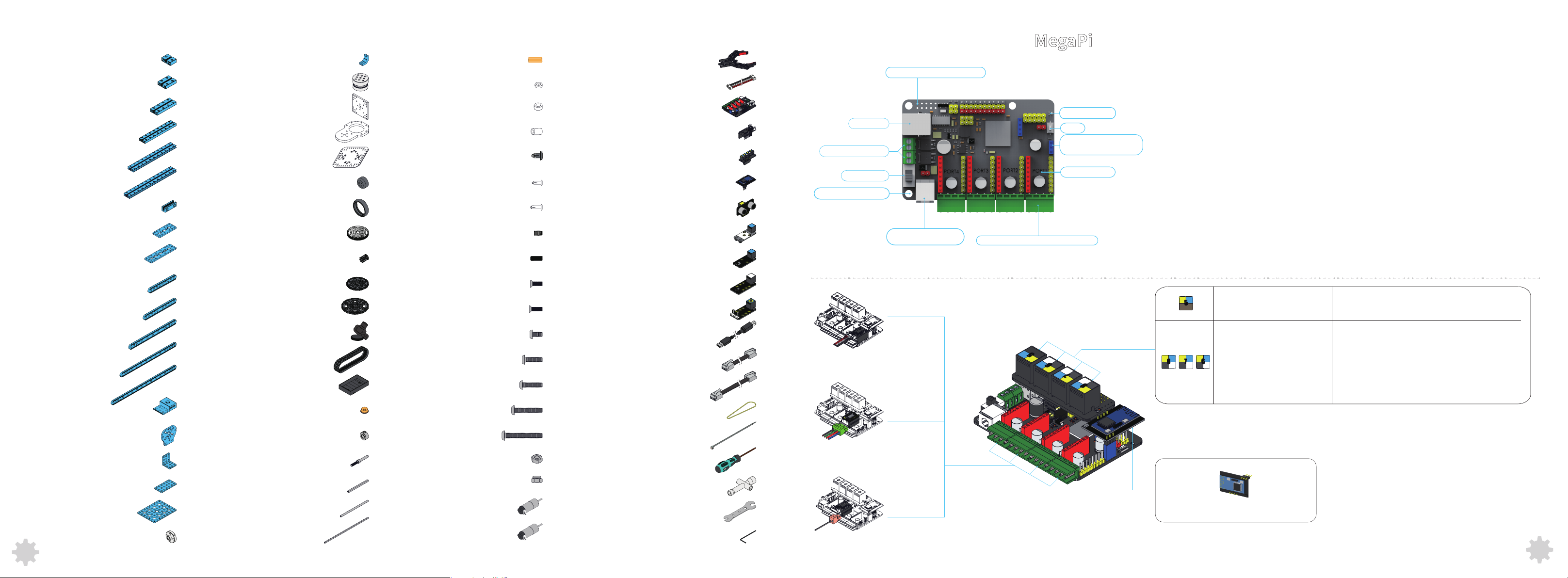
Basic Knowledge -- MegaPi
The various colors on MegaPi represents
specialized functions:
1. Red Pin--power output/motor output
2. Yellow Pin--I/O pin
3. Blue Pin--wireless communication interface
4. Black Pin--power GND
5. Green Interface--
power output/motor output
Technical Specifications
● Microcontroller: ATMEGA2560-16AU
● Input Voltage: DC 6V-12V
● Operating Voltage: DC 5V
● I/O Pins: 43
● Serial Ports: 3
● I
2
C Interface: 1
● SPI Interface: 1
● Analog Input Pins: 15
Bluetooth Communication Module
Hardware serial port Me Bluetooth
Me Bluetooth Module (Dual Mode)
Me Ultrasonic Sensor
Me RGB LED
Me Limit Switch
Me 7 Segment Serial Display
Me PIR Motion Sensor
Me Shutter
Me Line Follower
Me Infrared Receiver Decode
Me 3 Axis Accelerometer
and Gyro Sensor
Me Light and Grayscale
Sensor
Me Potentiometer
Me Joystick
Me 4 Button
Me Sound Sensor
One way digital interface
Dual digital interface
I²C port
Dual & one way analog interface
DC Motor Driver
Encoder Motor Driver
Stepper Motor Driver
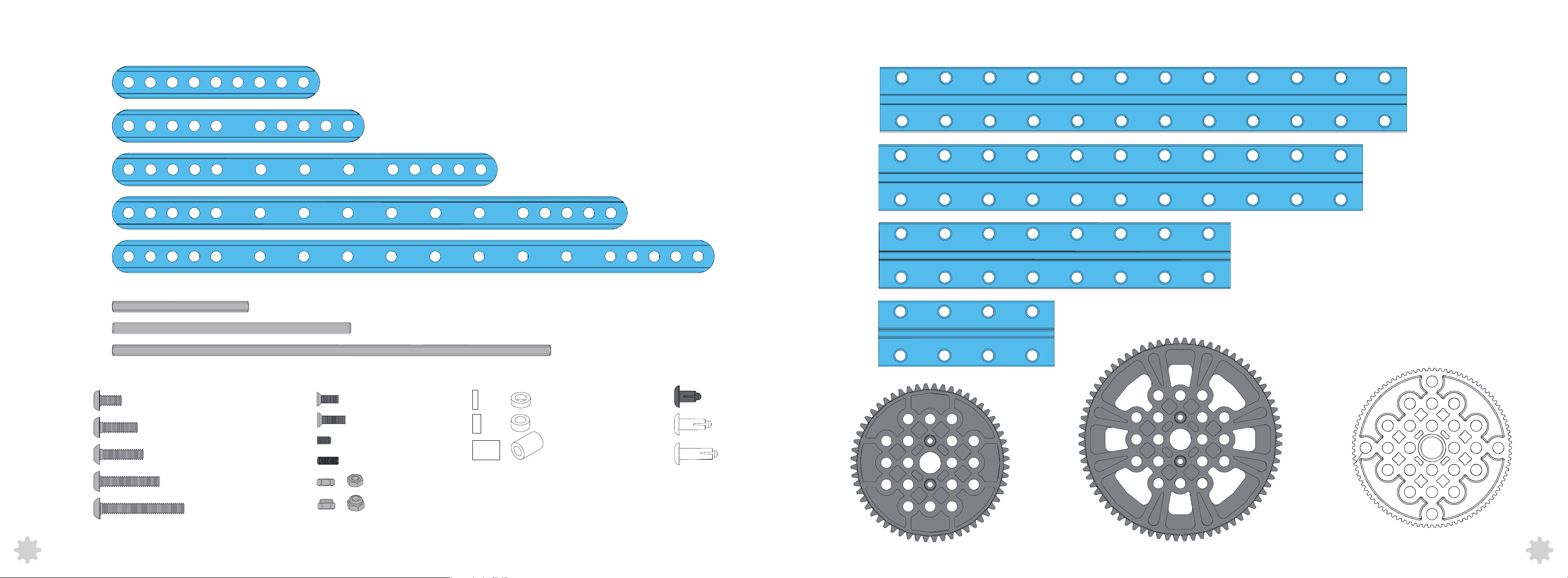
1× Plane Bearing TurntableD34x24mm
1× Quick Release Plate
4× Stiffener1616-08-M4
6× Shaft Connector 4mm
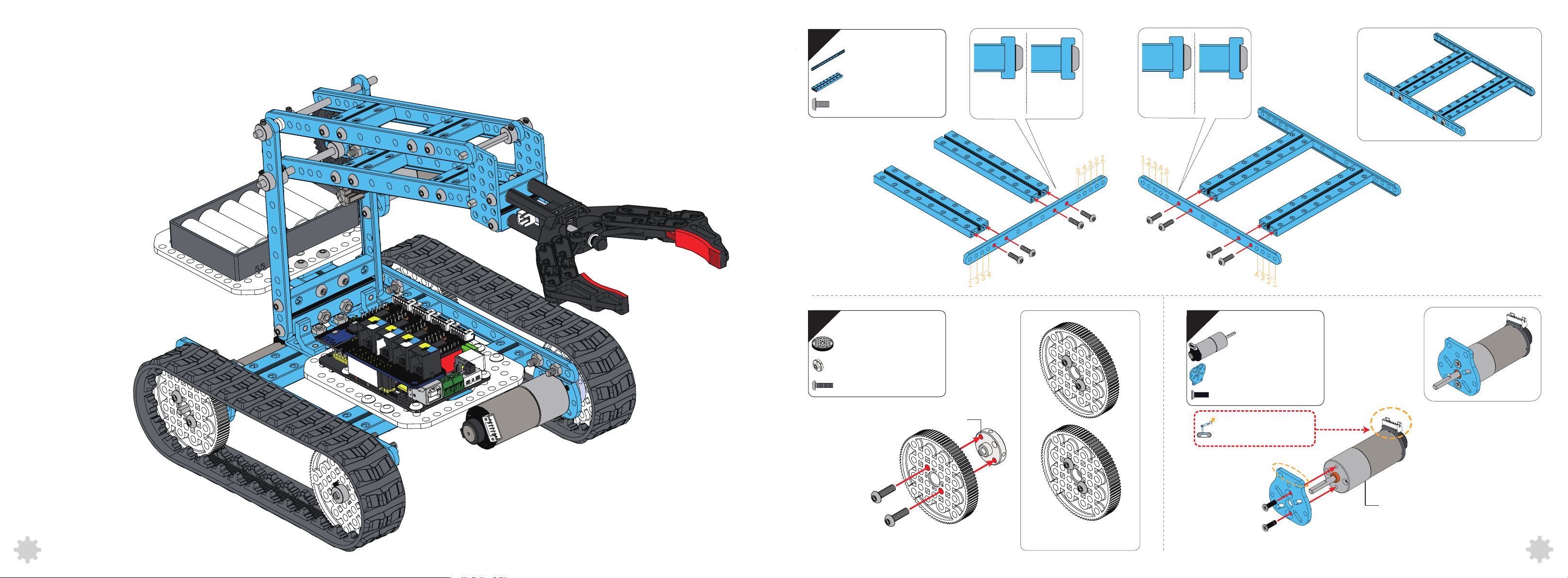
4× Beam0824-016
5× Beam0824-032
3× Beam0824-064
2× Beam0824-128
1× Slide Beam0824-176
2× Slide Beam0824-192
2× Beam0808-024
2× Beam0412-220
6× Beam0412-188
4× Beam0412-140
4× Beam0412-092
4× Beam0412-076
3× Plate0324-088
2× Plate0324-056
2× Bracket P3
1× Plate 7×9-B
2× Plate 3×6
4× Bracket 3×3
3× 25mm DC Motor Bracket
2× 25mm Motor Bracket-72T
2× MegaPi Acrylic Bracket
4× Rubber Blanket
4× Tire 90T B
6× Plastic Timing Pulley 90T
3× Plastic Gear 8T
2× Plastic Gear 56T
6× Threaded Shaft 4×39mm
12× Shaft Collar 4mm
12× Flange Copper Sleeve 4×8×4mm
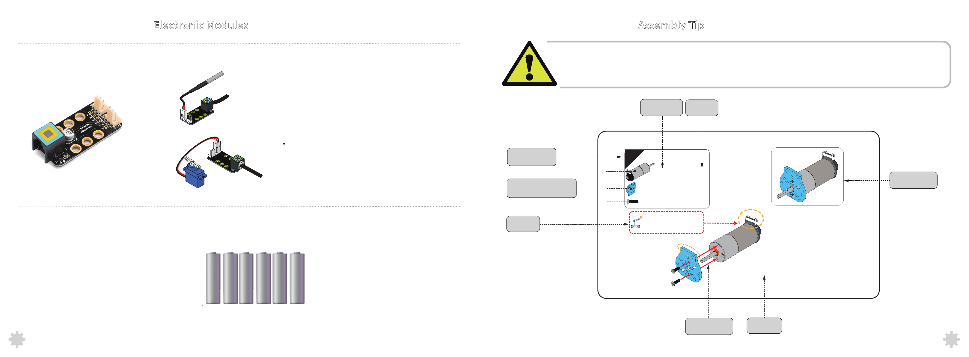
1× Battery Holder 6AA
2× Track 80×139mm
1× 360° Mobile Phone Bracket
2× Plastic Gear 72T
2× D shaft D4×50mm
20× Plastic Rivet 4060
20× Plastic Rivet 4100
2× Plastic Ring 4×7×10
8× Plastic Ring 4×7×3
4× Plastic Ring 4×7×2
4× Brass Stud M4×16
1× D shaft D4×160mm
2× Shaft D4×88mm
20× Plastic Rivet 4120
12×
Headless Set Screw M3×5
8× Headless Set Screw M3×8
6× Countersunk Screw M3×8
4× Countersunk Screw M3×10
50× Screw M4×8
46× Screw M4×14
2× 25mm DC Encoder
Motor 9V/185RPM
1× 25mm DC Encoder
Motor 9V/86RPM
10× Nylon Lock Nut M4
47× Nut M4
4× Screw M4×30
4× Screw M4×22
10× Screw M4×16
1× Makeblock Robot Gripper
1× Me Line Follower
1× Me Shutter
1× Me Ultrasonic Sensor
1× Bluetooth Module
1× Megapi Shield for RJ25
4× Megapi Encoder/DC Motor Driver
1× MegaPi
3× 25mm DC Encoder Motor Cable
1× Me 3-Axis Accelerometer
and Gyro Sensor
1× Me Adapter
1× USB Cable B-1.3m
2× 6P6C RJ25 Cable-20cm
1× 6P6C RJ25 Cable-35cm
10× Rubber Band
10× Nylon Cable Tie 1.9×100
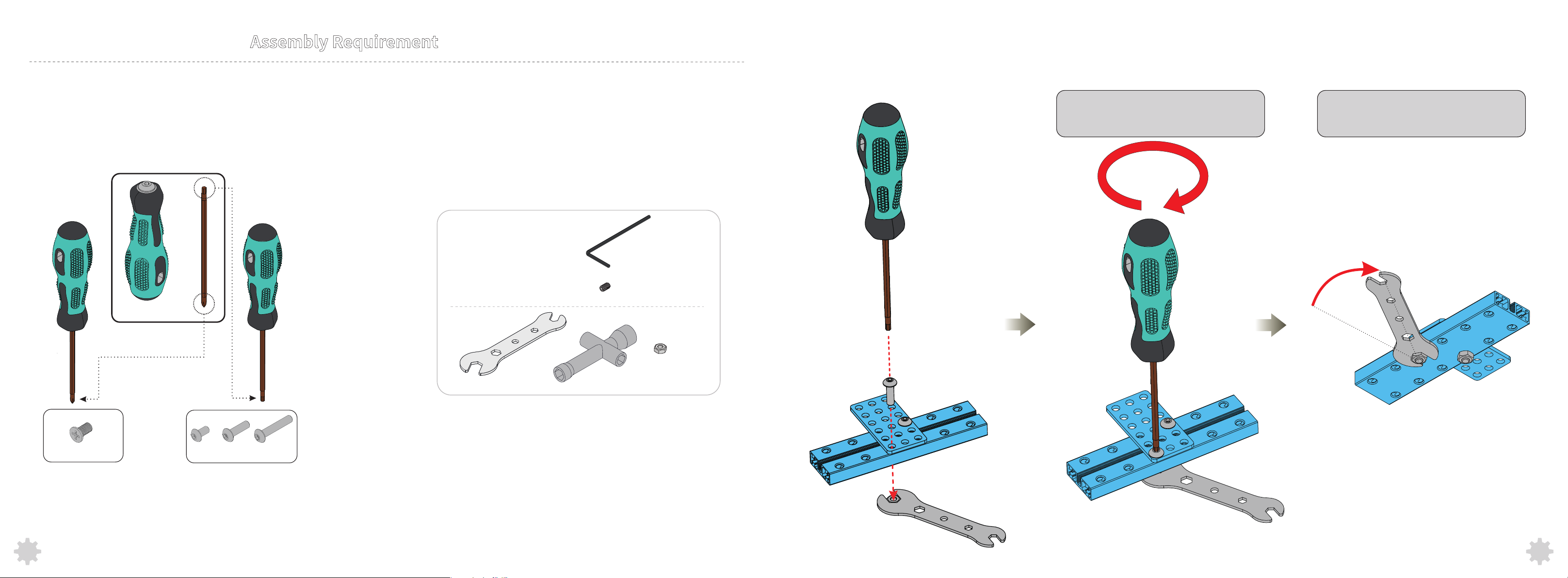
1× Wrench 5mm&7mm
1× Small Fourway Socket Wrench
1× HEX Key 1.5mm
1× Cross&2.5mm HEX Screwdriver
45
MegaPi is a main control board specially designed for makers and also an ideal option for being applied
to education field and all kinds of matches. It is based on Arduino MEGA 2560 and supports program-
ming with Arduino IDE perfectly. MegaPi can be divided into 6 function area, allowing you to connect
with various plug-in modules to drive motors and sensor and to realize wireless communication. MegaPi
has strong motor-driving ability which is capable of driving 10 servos or 8 DC motors simultaneously. It is
the ideal option for various robotic projects, such as smart robot car and 3D printer.
Power Indicator
USB-B type
Power Switch
High-Power DC
Power Supply (6-12V)
Raspberry Pi Communication
Reset
Wireless
Communication Module
Motor Driver*4
Stepper Motor/DC Motor Interface*4
High-Power Output
M4 Mounting Hole*3