Makita 4101RH User manual

Tile Cutter
110
mm
(4-318")
110
mm
(4-3/8")
MODEL
4101RH
236
mm
3.0
kg
(9-
114")
(6.6
Ibs)
12,000
34
mm
21
mm
(1-318")
(1
3/16")
INSTRUCTION MANUAL
I
1
S
PECl
F
I
CAT1
0
N
S
weight
I
Net
No
load speed Overall
(RPMI
length
Max. cutting capacities
Wheel
diameter

GENERAL SAFETY RULES
(For
All
Tools)
WARNING!
Read and understand all instructions.
Failure
to
follow
all
instructions
listed
below,
may
result
in
electric
shock,
fire
and/or
serious
personal
injury.
SAVE THESE INSTRUCTIONS
READ ALL INSTRUCTIONS.
WORK AREA
1.
Keep your work area clean and well
lit.
Cluttered benches and dark areas invite
accidents.
2.
Donot operate power tools
in
explosiveatmospheres, suchas
in
the presence
of flammable liquids, gases, or dust. Power tools create sparks which
may
ignite the dust or fumes.
3.
Keep bystanders, children, and visitors away while operating a power tool.
Distractions can cause you to lose control.
ELECT
Rl
CAL SAFETY
4.
Double Insulatedtools are equipped witha polarized plug(oneblade iswider
than the other.) This plug will
fit
in
a polarized outlet only one way.
If
the
plug does not
fit
fully in the outlet, reverse the plug.
If
it
still does not fit,
contact a qualified electrician to install a polarized outlet. Do not change
the plug in any way. Double insulation eliminates the need for the three
wire grounded power cord and grounded power supply system.
5.
Avoid body contact with grounded surfaces such as pipes, radiators, ranges
and refrigerators. There is an increased risk of electric shock if your body is
grounded.
6.
Don't expose power tools torain or wet conditions. Water entering a power
tool
will
increase the risk of electric shock.
7.
Do not abuse the cord. Never use the cord tocarry the tools
or
pullthe plug
from an outlet. Keep cord away from heat, oil, sharp edges or moving parts.
Replace damaged cords immediately. Damaged cords increase the risk of
electric shock.
8.
When operatinga power tooloutside, use an outdoor extension cord marked
"W-A" or "W." These cords are rated for outdoor use and reduce the risk
of electric shock.
PERSONAL SAFETY
9.
Stay alert, watchwhat you are doing and usecommonsense whenoperating
a power tool.
Do
not use tool while tired or under the influence of drugs,
alcohol, or medication.
A
moment of inattention while operating power tools
may result in serious personal injury.
IO.
Dressproperly. Donot wear loose clothingor jewelry. Containlonghair. Keep
your hair, clothing, andglovesaway from movingparts. Looseclothes, jewelry
or long hair can be caught
in
moving parts.
2

11. Avoid accidental starting. Be sure switch
is
off before plugging
in.
Carrying
tools with your finger onthe switch or plugging intools that have the switch
on invites accidents.
12.
Remove adjusting keys or switches before turning the tool on.
A
wrench or
a key that is left attached toa rotating part of the tool may result in personal
injury.
13.
Do
notoverreach. Keep proper footing and balanceatalltimes. Properfooting
and balance enables better control of the tool in unexpected situations.
14.
Use safety equipment. Always wear eye protection. Dust mask, non-skid
safety shoes, hard hat, or hearing protection must be used for appropriate
conditions.
TOOL
USE AND CARE
15. Use clamps or other practical way to secure and support the workpiece to
a stable platform. Holdingthe work by handor against your body is unstable
and may lead to
loss
of control.
16.
Do
notforce tool. Usethe correct tool for your application. The correct tool
will
do the job better and safer at the rate for which
it
is designed.
17.
Do
not use tool
if
switch does not turn
it
on or off. Any tool that cannot
be controlled with the switch is dangerous and must be repaired.
18.
Disconnect the plugfrom the power source before making any adjustments,
changing accessories, or storing the tool. Such preventive safety measures
reduce the risk of starting the tool accidentally.
19. Store idle tools out of reach of children and other untrained persons. Tools
are dangerous in the hands of untrained users.
20. Maintain tools with care. Keep cutting tools sharp and clean. Properly
maintained tools, with sharp cutting edges are less likely tobindand are easier
to
control.
21.
Check for misalignment or binding of moving parts, breakage of parts, and
any other condition that may affect the tools operation. If damaged, have
the tool serviced before using. Many accidents are caused by poorly main-
tained tools.
22. Use only accessories that are recommended by the manufacturer for your
model. Accessories that may be suitable for one tool, may become hazardous
when used on another tool.
SERVICE
23.
Tool
service must be performed only by qualified repair personnel. Service
or
maintenance performed by unqualified personnel could result in a risk
of
injury.
24.
When servicing a tool, use only identicalreplacement parts.
Follow
instruc-
tions in the Maintenance section of this manual. Use of unauthorized parts
or failure tofollow Maintenance Instructionsmay create a risk of electric shock
or injury.
3

Specific Safety Rules
1.
DANGER! Keep hands away from cutting area and blade. Keep your second
handonauxiliary handle, or motorhousing. If bothhands are holdingthe saw,
they cannot be cut by the blade.
Keep your body positionedtoeither side of the saw blade, but not
in
line with
the saw blade. KICKBACK could cause the saw to jump backwards. (See
"Causes and Operator Prevention of Kickback")
Do notreachunderneaththe work. Don't remove to remove cut material when
blade is moving.
CAUTION: Blades coast after turn off.
2.
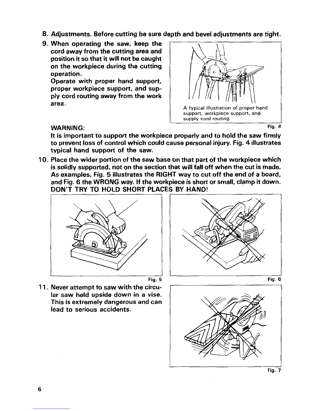
NEVER hold piece being cut
in
your hands or across your leg. It is important
tosupport the work properlyto minimize body exposure, blade binding, or
loss
of control.
3.
Holdtool by insulatedgripping surfaces when performingan operation where
the cutting tool may contact hidden wiring or its own cord. Contact
with
a
"live" wire
will
also make exposed metal parts
of
the tool "live" and shock
the operator.
4.
When rippingalways usea ripfence or straight edge guide. This improves the
accuracy of cut and reduces the chance for blade binding.
5.
Always useblades withcorrectsize andshape (diamondvs. round) arbor holes.
Blades
that
do not matchthe mounting hardware of the saw will runeccentri-
cally, causing
loss
of control.
6.
Never use damaged or incorrect blade washers or bolts. The blade washers
and bolt were specially designed for your saw, for optimum performance and
safety or operation.
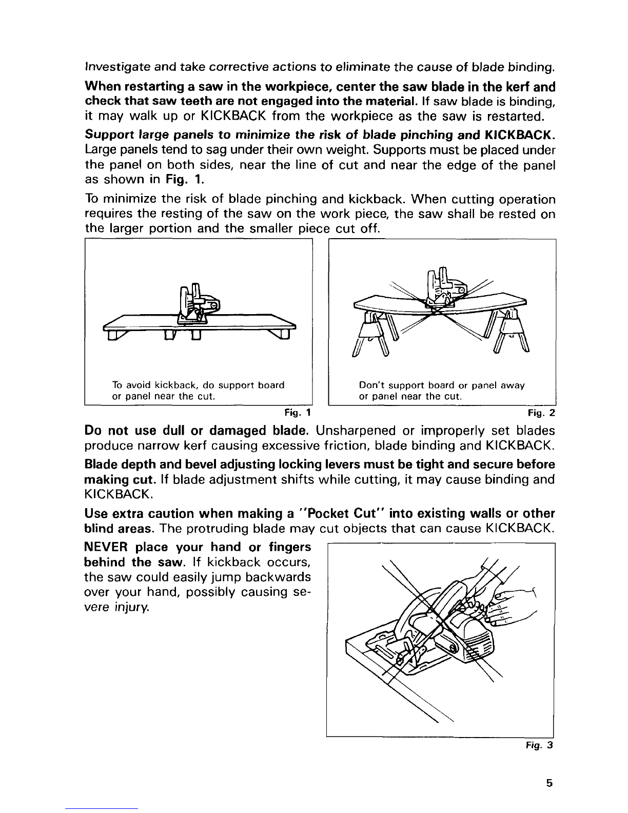
Kickback is a sudden reaction to a pinched, bound or misaligned saw blade,
causing an uncontrolled saw to lift up and out of the workpiece toward the
operator.
Whenthe blade is pinched
or
bound tightly by the kerf closing down, the blade
stalls and the motor reaction drives the unit rapidly back toward the operator.
If the blade becomes twisted or misaligned in the cut, the teeth at the back
edge of the blade candig into the top surface of the material being cutcausing
the blade to climb out of the kerf and jump back toward operator.
Kickback
is
the result of tool misuse and/or incorrect operating procedures or
conditions and can be avoided by taking proper precautions as given below.
Maintain a firm grip with both hands onthe saw and position your body and
arm to allow you to resist KICKBACK forces. KICKBACK forces can be
controlled by the operator, if proper precautions are taken.
When blade is binding, or when interrupting a cutfor any reason, release the
trigger and hold the saw motionless in the material untilthe blade comes to
a complete stop. Never attempt to remove the saw from the work or
pull
the saw backward while the blade is
in
motion or KICKBACK may occur.
7.
Causes and Operator Prevention of Kickback:
4

Investigate andtake corrective actions toeliminate the cause of blade binding.
When restartinga saw
in
the workpiece, center the saw blade
in
the kerf and
check that saw teeth are not engagedintothe material. If saw bladeis binding,
it
may walk up or KICKBACK from the workpiece as the saw is restarted.
Support large panels to minimize the
risk
of blade pinching and
KICKBACK.
Large panelstend to sag undertheir ownweight. Supports must beplacedunder
the panel on both sides, near the line of cut and near the edge of the panel
as shown in Fig.
1.
To
minimize the risk of blade pinching and kickback. When cutting operation
requires the resting of the saw on the work piece, the saw shall be rested on
the larger portion and the smaller piece cut off.
To
avoid kickback, do support board
or panel near the cut. Don't support board or panel away
or
panel near the
cut.
Fig.
1
Fig.
:
Do
not use dull
or
damaged blade. Unsharpened or improperly set blades
produce narrow kerf causing excessive friction, blade binding and KICKBACK.
Bladedepth and beveladjustinglockinglevers must betight and securebefore
making cut. If blade adjustment shifts while cutting,
it
may cause binding and
KICKBACK.
Use extra caution when making a "Pocket Cut" into existing walls or other
blind areas. The protruding blade may cut objects that can cause KICKBACK.
NEVER
place your hand or fingers
behind the saw. If kickback occurs,
the saw could easily jump backwards
over your hand, possibly causing se-
vere injury.
Fig.
C
5

8.
Adjustments. Before cutting be sure depth and beveladjustments are tight.
I
I
9.
When operating the saw, keep the
cord away from the cutting area and
position
it
so
that
it
willnotbecaught
on the workpiece during the cutting
operation.
Operate with proper hand support,
proper workpiece support, and sup-
ply cordroutingaway from the work
area.
WARN
IN
G
:
A
typical illustration
of
proper hand
support, workpiece support, and
supply cord routing.
Fig.
1
It
isimportanttosupport the workpiece properly andtohold the saw firmly
toprevent
loss
of control which could cause personalinjury. Fig.
4
illustrates
typical hand support of the saw.
10.
Placethewider portion of thesaw baseonthat partof the workpiece which
issolidly supported, notonthe section that willfalloff whenthe cut ismade.
As
examples, Fig.
5
illustrates the RIGHT way tocut off the end of a board,
and Fig.
6
the WRONG way. Ifthe workpiece is short or small, clamp
it
down.
DON'T TRY TO HOLD SHORT PLACES
BY
HAND!
I
Fig.
'
I
Fig.
11.
Neverattemptto saw withthecircu
tar saw held upside down
in
a
vise.
This isextremely dangerous andcan
lead to serious accidents.
6

12.
If the plug or receptacle does get wet, DON'T unplugthe cord. Disconnect
the fuse or circuit breaker that supplies power tothe tool. Then unplug and
examine for presence of water
in
the receptacle.
13.
WARNING
-
To
reduce the risk of electrocution when using an extension
cord, keep
ALL
connections dry and off the ground.
14.
Ground Fault Circuit Interrupter (GFCI)protection should be providedonthe
circuit(s1or outlet(s)to be usedfor the tool. Receptaclesare availablehaving
built-in GFCI protection and may be used for this measure of safety.
SAVE THESE INSTRUCTIONS.
7

SYMBOLS
The followings show the symbols usedfor tool.
v
.................................
volts
A
.................................
amperes
HZ
.................................
herts
.................................
kilograms
kg
h
.................................
hours
min
.................................
minutes
S
.................................
seconds
TJ
.................................
alternating current
-
direct current
____
.................................
n,
.................................
no load speed
'L
.................................
alternating or direct current
-
.................................
Class
II
Construction
A
.................................
splash-proof construction
AA
.................................
watertight construction
...
/min
................................
revolutions or reciprocation per minute
b
.................................
number of blow
8

Functional Description
Ground Fault Circuit Interrupter
Connectthe tool to
a
power supply andtest
the Ground Fault Circuit Interrupter (GFCI)
before using the tool. Push the RESET
(R)
button and confirm that the pilot lamp
lights. Push the
TEST
(TI
button and con-
firm that the pilot lamp goes out. Push the
RESET
(R)
button again to use the tool.
WARN
I
NG:
Do
not use the tool if the pilot lamp does
not go out when the
TEST
(TI button is
pushed.
Switch action
CAUTION:
I
Pilot
)amp
RESET
(R)
Button
TEST
-
button
~
Before plugging in the tool, always check to see that the switch trigger actuates properly
and returns to the "OFF"position when released.
To
prevent the switch trigger from being
1
accidentally pulled,
a
lock-off button is pro-
vided.
To
start the tool, depress the lock-off but-
ton and pull the switch trigger. Releasethe
switch trigger to stop.
Lock-off
button
1
I
Switch
trigger
9

Partname
Pressure regulator
Description
Adaptor
Vinyl tube
Water pipe
Presetat about 15 psi.
314" female hose thread (inlet)
x
314" male hose thread (outlet)
Flowcapacity: Maximum
390
GPH. minimum 10 GPH
Inletpressures: Maximum 100 psi, minimum 25 psi
For connecting 1/4" vinyl tube to
a
faucet.
314" swivel
x
114'' adaptor
1/4" inouter diameter
x
1
111
6"
in inner diameter
x
18' in length
For adjustingthe amount of water flow
Assemble the above partshandtight as follows.
*Cut the vinyl tube
at
an angle for easier
insertion, Push the end of the vinyl tube
intothe end
of
the adaptor using
a
combi-
nation pushingand twisting motion.
Screw the pressure regulator tight on the
adaptor.
Connect the vinyl tube firmly
to
the water
pipe.
Pressure
regulator
assembly
I
Tighten
,"
Adaotor
//
Vinvl
tube
Water
pipe
I
10

Assembly
Installing
water
pipe
Unplug the tool. Loosen the wing bolt on
the depth guide and move the base down.
Install the water pipe on the blade case
usingthe screw.
Screw the pressure regulator tight
on
a
faucet.
Adjust the amount
of
water flow by simply
adjustingthe water cock.
CAUTION:
Do
not connect the adaptor directly to
a
faucet.
If you do
so,
the vinyl tube may come off
the water pipe during operation.
I
1
I
Water
pipe
11

Removing or installingdiamond wheel
CAUTIO
N
:
Always be sure that the tool is switched off and unplugged before installing or removing
the wheel.
Hold the outer flange with the wrench and
loosen the hex socket head bolt clockwise
direction with the hex wrench. Then
remove the hex socket head bolt, and outer
flange.
/
Loosen
\
Install the diamond wheel, outer flange
and hex socket head bolt onto the spindle.
Hold the outer flange with the wrench and
tighten the hex bolt in counterclockwise
direction with the hex wrench. BE SURE
TO TIGHTEN THE HEX SOCKET HEAD
BOLT
SECURELY.
CAUTION:
Useonly the Makita wrench and hex wrench to install or removethe wheel.
Installing
cover
"A"
Install the cover "A" on the tool
so
that its
side with "Upside
U"
mark faces upward.
12

Operation
Adjust the amount
of
water flow. Hold the
tool firmly. Set the base plate on the work-
piece to be cut without the wheel making
any contact. Then turn the tool on and wait
until the wheel attains full speed. Now
simply move the tool forward over the
workpiece surface, keeping it flat and ad-
vancing smoothly until the cutting is com-
pleted. Keep your cutting line straight and
your speed of advance uniform.
Sighting
For straight cuts, align the left edge of the
base with your cutting line on the work-
CAUTION
:
.THIS
TOOL SHOULD ONLY BE USED ON HORIZONTAL SURFACES.
*Be sureto movethe tool forward in
a
straight lineand gently. Forcingand exerting exces-
sive pressureor allowing the wheel to bend,pinchor twist in the cut can causeoverheat-
ingof the motor and dangerous kickbackof the tool.
*Since excessive cutting may cause overload
of
the motor, the depth of cut should not be
more than
20
mm
(13/16")
at
a
pass.When you wish to cut morethan
20
mm
(13/16")
deep, make
a
couple of passeswith progressivelydeeper settings.
I
piece.
For
45"
bevelcuts, align the left edge of the
top guidewith it.
Base
&
13

Adjusting depth
of
cut
Loosen the wing bolt on the depth guide
and move the base up or down. At the
desired depth of cut, secure the base by
tightening the wing bolt.
Adjusting bevel angle
Loosen the wing nut on the bevel scale
plate on the front of the base. Set for the
desired angle
(0
-
45")
by tilting according-
ly, then tighten the wing nut securely.
Loosen the wing bolt on the depth guide
and move the base
so
that the end
of
the
blade case is above the red line on the
depth guide. Then tighten the wing bolt to
secure the base.
NOTE:
I
If
the end of the bladecase
is
under the red line on the depth guide, the outer flange may
hitthe workpiece when you perform the bevelcut.
14

MAINTENANCE
CAUTION:
Always be sure that the
tool
is switched off and unplugged before attempting to perform
inspection or maintenance
After
use
Blowaway dust from the insideof the tool by runningthe tool at an idlefor awhile.
Brush off accumulation of dust on the base.
Accumulation of dust inthe motor or on the base may cause
a
malfunction of the tool.
Cleaning
covers
When accumulation of dust on the cover
"A"
looks
excessive, loosenthe clamp and
remove the cover "A". Wash off accumula-
tion of dust inside the cover "A" and wipe
it. Then install the cover "A" on the tool
so
that its side with "Upside
tf
"
mark faces
upward. Push the cover "A" toward the
motor as far as it will go and secure
it
by
tighteningthe clamp.
When changing the wheel, clean the cover
"B" at the same time. Loosen the screw
securing the cover "B" and remove the
cover "B". Wash off accumulation of dust
inside the cover "B" and wipe it. Then
attach the cover
"B"
to the tool by tighten-
ing the screw. Accumulation of dust inside
the covers may cause a malfunction of the
tool.
-
Cover
"A"
I
Screw
CAUTl
ON
:
When usingthe tool, be sure to attach the covers
"A"
and "B"
15

Replacingcarbon brushes
Remove and check the carbon brushes
regularly. Replace when they wear down
to the limit mark. Keep the carbon brushes
clean and free to slip in the holders. Both
carbon brushes should be replaced at the
same time. Use only identical carbon
brushes.
First,removethe cover
"A".
Use
a
screwdriver to remove the brush
holder caps. Take out the worn carbon
brushes, insert the new ones and secure
the brushholder caps.
/
Limit
mark
Dressingdiamond wheel
If the cuttingaction of the diamond wheel begins to diminish, use an old discarded coarse
grit bench grinder wheel or concrete blockto dress the diamond wheel.
To
do this,tightly
secure the bench grinder wheel or concrete block and cut in it.
To
maintainproduct
SAFETY
and
RELIABILITY,
repairs, any other maintenance or adjust-
ment should be performedby MakitaAuthorized or Factory Service Centers, always using
Makitareplacementparts.
16

ACCESSORIES
CAUTION:
These accessories or attachments are recommendedfor use with your Maktta tool specified in this
manual, The use of any other accessories or attachments might present
a
risk
of
injury to persons
The accessories
or
attachments should
be
usedonly in the proper and intendedmanner.
Hex wrench
5
Part
No.
783203-8
Guide rule
Part
No.
164095-8
Pressure regulator assembly
Wrench
22
Part
No.
781011-1
Diamond wheel
For
all
stone
and masonry materials,
tiles
etc.
17

Feb-26-'99
US
110
mm
(4-3/8")
CUTTER
Model
4101RH
Note: The switch and other part configurations
may differ from country to country.
18

MODEL
4101RH
Feb.-26-'99
US
MACHINE
34
35
36
37
38
39
40
41
42
43
44
45
46
47
48
49
50
51
52
53
54
55
56
59
60
61
62
63
64
65
58
'LN'$n
DESCRIPTION
1
1
1
1
1
1
1
1
1
1
1
1
1
2
2
I
1
1
1
1
1
2
2
i
1
1
1
1
1
1
1
MACHINE
10
11
12
13
14
15
16
17
18
19
20
22
23
24
25
26
27
26
29
30
31
32
33
Hex
Socket
Head Bolt
M6x20
Outer
Flange 36
Inner
Flange 36
0
Ring
18
Bearing
Retainer
19-33
Spindle
Woodruff
Key
4
Her
Bolt M4x25
Blade
Case
Complere
Pan
Head
Screw
M4x14
Pipe
Complete
Cover B
Pan
Head
Screw
M5x8
Gear Housing
Complete IWith
Item
151
0
Ring
26
Baffie
Plate
Seal
Rubber
Cover A
Clamp
90
Pan
Head
Screw
M5x35
Needle
Bearing
810
Relaining
Ring
S-
12
Name
Plate
Pan
Head
Screw
M4x25
'
Pan
Hedd
Screw M5r40
Motor
Housing
Complete [With
Item
461
1
Ball
Bearing
6201DDW
FIELD
ASSEMBLY
0
Ring
16
1
Helical
Gear
42
11
21
31
41
51
61
71
64
91
1
1
1
1
1
1
1
1
1
1
1
1
1
1
1
4
2
1
1
1
1
1
1
Insulation Washer
ARMATURE ASSEMBLY
(With Item 33. 34
&
36
-
381
Fan
66
Flat Washer
9
Ball
Bearing
629LLB
Helical
Gear
19
Retaining
Ring
S-8
Woodruff Key
3
Wing Nut M6
Spring Washer
6
Flat Washer
6
Base
Rubber Pin 4
Pan
Head
Screw
M5x65
Pan
Head Screw
M4x18
Strain
Relief
Handle
Cover Complete
Cord
Guard
Cord
0"s
cover
Swmh
Carbon Brush
Holder
Cap
Wing Bolt M6x10
Spring Washer
6
Cap
Square
Neck
Bolt M6x20
Spring Pin 6-32
Flat Washer
6
Terminal
Block
1P
Lead
Unit
Pan
Head
Screw
M4x8
Note
The
swttch
and other
part
specifications
may
dilfer
from
country
to
country
19

MAKITA
LIMED
ONE
YEAR
WARRANTY
Warranty
Policy
Every Makita
tool
is thoroughly inspected and tested before leavingthe factory.
It
is warranted to
be free of defects from workmanshiv and materials for the veriod of ONE YEAR from the date of
ongnal purchase. Should any troubie develop dunng this dne-year penod. return ihe COMPLtTt
tool. freight prepaid,
to
one of Makita’s Factory or Authonzed ServiceCenters
If
inspection rhous
the trouble is caused by defective workmanship or matenal, Makita will repair (or at our option,
replace) without charge.
This Warranty does not apply where:
repairs have been made or attempted
by
others:
repairs are required because of normal wear and tear:
The tool has been abused, misused or improperly maintained;
alterations have been made to the tool.
IN
NO EVENT SHALL MAKITA BE LIABLE FOR ANY INDIRECT, INCIDENTAL OR CON-
SEQUENTIAL DAMAGES FROM THE SALE OR USE OFTHE PRODUCT.THIS DISCLAIMER
APPLIES BOTH DURING AND AFTER THE TERM OFTHIS WARRANTY.
MAKITA DISCLAIMS LIABILITY FOR ANY IMPLIED WARRANT1t.S. INCLUDING
IMPLII
D
WARRANTIES OF “MERCHANTABILITY” AND
“FITNESS
FOR
A
SPFClFlC
PlJRPOSl
,”
AFTER THE ONF-YEAR TERM
OF
THIS WARRANTY.
This
Warranty gives you specific legal rights, and you may also have other rights which vary from
state to state. Some states do not allow the exclusion or limitation of incidental or consequential
damages,
so
the above limitation
or
exclusion may
not
apply to you. Some states do not allow
limitation on how long an implied warranty lasts,
so
the above limitation may not apply
IO
you.
Makita Corporation
3-11
-8, Sumiyoshi-cho,
Anjo, Aichi 446-8502
Japan
004156AQ67 PRINTED
IN
JAPAN
1999
-
5
-
N
Other manuals for 4101RH
17
Table of contents
Other Makita Cutter manuals

Makita
Makita DPC6410 (UK) Quick start guide

Makita
Makita 4105KB User manual

Makita
Makita 4107R User manual

Makita
Makita CE001G User manual

Makita
Makita DPC6411 (USA) Instruction Manual

Makita
Makita CC301D User manual

Makita
Makita M2402 User manual

Makita
Makita CP100D User manual

Makita
Makita DCS553 User manual

Makita
Makita 4131 User manual

Makita
Makita EK7650H Instruction Manual

Makita
Makita 4100KB User manual

Makita
Makita 4100NH User manual

Makita
Makita 180 mm 4157KB User manual

Makita
Makita SC103D User manual

Makita
Makita 3803A User manual

Makita
Makita CA5000 User manual

Makita
Makita CA5000X User manual

Makita
Makita 4100NH User manual

Makita
Makita DCE090 User manual