Makita 4131 User manual

GB
Metal Cutter Instruction Manual
F
Scie à métal Manuel d’instructions
D
Metallkreissäge Betriebsanleitung
I
Troncatrice per metallo Istruzioni per l’uso
NL
Metaalzaag Gebruiksaanwijzing
E
Cortador de metales
Manual de instrucciones
P
Cortador de metal Manual de instruções
DK
Metalskæremaskine Brugsanvisning
S
Metallsåg Bruksanvisning
N
Metallsag Bruksanvisning
SF
Metallisaha Käyttöohje
GR Κπτης µετάλλων Οδηγίες χρήσεως
4131

2
12
34
56
78
16
17
14
15
10
11 12
13
8
9
67
45
A
3
1
2

3
910
11 12
13 14
15
22 23
21
67
19
20
19
18
12
18

4
Symbols
The followings show the symbols used for the tool. Be sure that you understand their meaning before use.
Symboles
Nous donnons ci-dessous les symboles utilisés pour l’outil. Assurez-vous que vous en avez bien compris la significa-
tion avant d’utiliser l’outil.
Symbole
Die folgenden Symbole werden für die Maschine verwendet. Machen Sie sich vor der Benutzung unbedingt mit ihrer
Bedeutung vertraut.
Simboli
Per questo utensile vengono usati i simboli seguenti. Bisogna capire il loro significato prima di usare l’utensile.
Symbolen
Voor dit gereedschap worden de volgende symbolen gebruikt. Zorg ervoor dat u de betekenis van deze symbolen
begrijpt alvorens het gereedschap te gebruiken.
Símbolos
A continuación se muestran los símbolos utilizados con esta herramienta. Asegúrese de que entiende su significado
antes de usarla.
Símbolos
O seguinte mostra os símbolos utilizados para a ferramenta. Certifique-se de que compreende o seu significado antes
da utilização.
Symboler
Nedenstående symboler er anvendt i forbindelse med denne maskine. Vær sikker på, at De har forstået symbolernes
betydning, før maskinen anvendes.
Symboler
Det följande visar de symboler som används för den här maskinen. Se noga till att du förstår deras innebörd innan
maskinen används.
Symbolene
Følgende viser de symblene som brukes for maskinen. Det er viktig å forstå betydningen av disse før maskinen tas i
bruk.
Symbolit
Alla on esitetty koneessa käytetyt symbolit. Opettele näiden merkitys, ennen kuin käytät konetta.
Σύµβολα
Τα ακλουθα δείχνουν τα σύµβολα που χρησιµοποιούνται για το µηχάνηµα. Βεβαιωθείτε τι καταλαβαίνετε
τη σηµασία τους πριν απ τη χρήση.
❏Read instruction manual.
❏Lire le mode d’emploi.
❏Bitte Betriebsanleitung lesen.
❏Leggete il manuale di istruzioni.
❏Lees de gebruiksaanwijzing.
❏Lea el manual de instrucciones.
❏Leia o manual de instruções.
❏Læs brugsanvisningen.
❏Läs bruksanvisningen.
❏Les bruksanvisingen.
❏Katso käyttöohjeita.
❏∆ιαβάστε τις οδηγίες χρήσης.
❏DOUBLE INSULATION
❏DOUBLE ISOLATION
❏DOPPELT SCHUTZISOLIERT
❏DOPPIO ISOLAMENTO
❏DUBBELE ISOLATIE
❏DOBLE AISLAMIENTO
❏DUPLO ISOLAMENTO
❏DOBBELT ISOLATION
❏DUBBEL ISOLERING
❏DOBBEL ISOLERING
❏KAKSINKERTAINEN ERISTYS
❏ ∆ ΠΛΗ ΜΟΝΩΣΗ
❏Pay attention! It may become too hot.
❏Prenez garde ! Il y a risque de brûlure.
❏Achtung! Kann sehr heiß werden.
❏Attenzione! Può diventare estremamente caldo.
❏Let op! Kan zeer heet zijn.
❏¡Preste atención! Podrá calentarse mucho.
❏Tenha cuidado! Pode ficar muito quente.
❏Vær agtpågivende! Den kan blive for varm.
❏Varning! Den kan bli för het.
❏Pass på! Den kan bli for varm.
❏Varo! Voi kuumentua liikaa.
❏Προσέχετε! Μπορεί να υπερθερµανθεί.

5
ENGLISH
Explanation of general view
1Lever
2 Depth guide
3 Cutting line
4 Switch trigger
5 Lock-off button
6 Dust cover
7Knob
8Hexwrench
9 Shaft lock
10 Hex socket head bolt
11 Outer flange
12 Carbide-tipped saw blade
13 Inner flange
14 Slot
15 Rib
16 Rip fence (Guide rule)
17 Screw
18 Workpiece
19 Sight window
20 Retracting lever
21 Limit mark
22 Screwdriver
23 Brush holder cap
SPECIFICATION
• Due to our continuing program of research and devel-
opment, the specifications herein are subject to change
without notice.
• Note: Specifications may differ from country to country.
Intended use
The tool is intended for cutting in mild steel.
Power supply
The tool should be connected only to a power supply of
the same voltage as indicated on the nameplate, and can
only be operated on single-phase AC supply. They are
double-insulated in accordance with European Standard
and can, therefore, also be used from sockets without
earth wire.
Safety hints
For your own safety, please refer to the enclosed safety
instructions.
ADDITIONAL SAFETY RULES FOR TOOL
ENB082-3
DANGER:
1. Keep hands away from cutting area and the
blade. Keep your second hand on auxiliary han-
dle, or motor housing. If both hands are holding
the tool, they cannot be cut by blade.
2. Do not reach underneath the workpiece. The
guard cannot protect you from the blade below the
workpiece.
3. Adjust the cutting depth to the thickness of the
workpiece. Less than a full tooth of the blade teeth
should be visible below the workpiece.
4. Never hold piece being cut in your hands or
across your leg. Secure the workpiece to a sta-
ble platform. It is important to support the work
properly to minimize body exposure, blade binding,
or loss of control.
5. Hold power tool by insulated gripping surfaces
when performing an operation where the cutting
tool may contact hidden wiring or its own cord.
Contact with a “live” wire will also make exposed
metal parts of the power tool “live” and shock the
operator.
6. When ripping always use a rip fence or straight
edge guide. This improves the accuracy of cut and
reduces the chance of blade binding.
7. Always use blades with correct size and shape
(diamond versus round) of arbour holes. Blades
that do not match the mounting hardware of the tool
will run eccentrically, causing loss of control.
8. Never use damaged or incorrect blade washers
or bolt. The blade washers and bolt were specially
designed for your tool, for optimum performance and
safety of operation.
9. Causes and operator prevention of kickback;
• Kickback is a sudden reaction to a pinched,
bound or misaligned saw blade, causing an
uncontrolled tool to lift up and out of the work-
piece toward the operator.
• When the blade is pinched or bound tightly by
the kerf closing down, the blade stalls and the
motor reaction drives the unit rapidly back
toward the operator.
• If the blade becomes twisted or misaligned in
the cut, the teeth at the back edge of the blade
can dig into the top surface of the workpiece
causing the blade to climb out of the kerf and
jump back toward the operator.
Model 4131
Balde diameter 185 mm
Max. cutting capacity 63 mm
No load speed (min–1)3,500
Overall length 358 mm
Net weight 4.8 kg
Safety class /II
A typical illustration of proper hand support,
workpiece support, and supply cord routing
(if applicable).

6
Kickback is the result of tool misuse and/or
incorrect operating procedures or conditions
and can be avoided by taking proper precautions
as given below.
a. Maintain a firm grip with both hands on the
tool and position your arms to resist kickback
forces. Position your body to either side of the
blade, but not in line with the blade. Kickback
could cause the tool to jump backwards, but kick-
back forces can be controlled by the operator, if
proper precautions are taken.
b. When blade is binding, or when interrupting a
cut for any reason, release the trigger and
hold the tool motionless in the material until
the blade comes to a complete stop. Never
attempt to remove the tool from the work or
pull the tool backward while the blade is in
motion or kickback may occur. Investigate and
take corrective actions to eliminate the cause of
blade binding.
c. When restarting a tool in the workpiece, cen-
tre the saw blade in the kerf and check that
saw teeth are not engaged into the material. If
saw blade is binding, it may walk up or kickback
from the workpiece as the tool is restarted.
d. Support large panels to minimise the risk of
blade pinching and kickback. Large panels
tend to sag under their own weight. Supports
must be placed under the panel on both sides,
near the line of cut and near the edge of the
panel.
e. Do not use dull or damaged blades. Unsharp-
ened or improperly set blades produce narrow
kerf causing excessive friction, blade binding and
kickback.
f. Blade depth and bevel adjusting locking
levers must be tight and secure before making
cut. If blade adjustment shifts while cutting, it may
cause binding and kickback.
10. Check lower guard for proper closing before
each use. Do not operate the tool if lower guard
does not move freely and close instantly. Never
clamp or tie the lower guard into the open posi-
tion. If tool is accidentally dropped, lower guard may
be bent. Raise the lower guard with the retracting
lever and make sure it moves freely and does not
touch the blade or any other part, in all angles and
depths of cut.
11. Check the operation of the lower guard spring. If
the guard and the spring are not operating prop-
erly, they must be serviced before use. Lower
guard may operate sluggishly due to damaged
parts, gummy deposits, or a build-up of debris.
12. Always observe that the lower guard is covering
the blade before placing tool down on bench or
floor. An unprotected, coasting blade will cause the
tool to walk backwards, cutting whatever is in its
path. Be aware of the time it takes for the blade to
stop after switch is released.
13. Do not stop the blades by lateral pressure on the
saw blade.
14. DANGER:
Don’t attempt to remove cut material when blade
is moving.
CAUTION: Blades coast after turn off.
15. Place the wider portion of the saw base on that
part of the workpiece which is solidly supported,
not on the section that will fall off when the cut is
made.
As example, Fig. A illustrates the RIGHT way to
cut off the end of a board, and Fig. B the WRONG
way. If the workpiece is short or small, clamp it
down. DON’T TRY TO HOLD SHORT PIECES BY
HAND! (Fig. B)
Fig. A
Fig. B
To avoid kickback, do support board or panel
near the cut.
Do not support board or panel away from the cut.

7
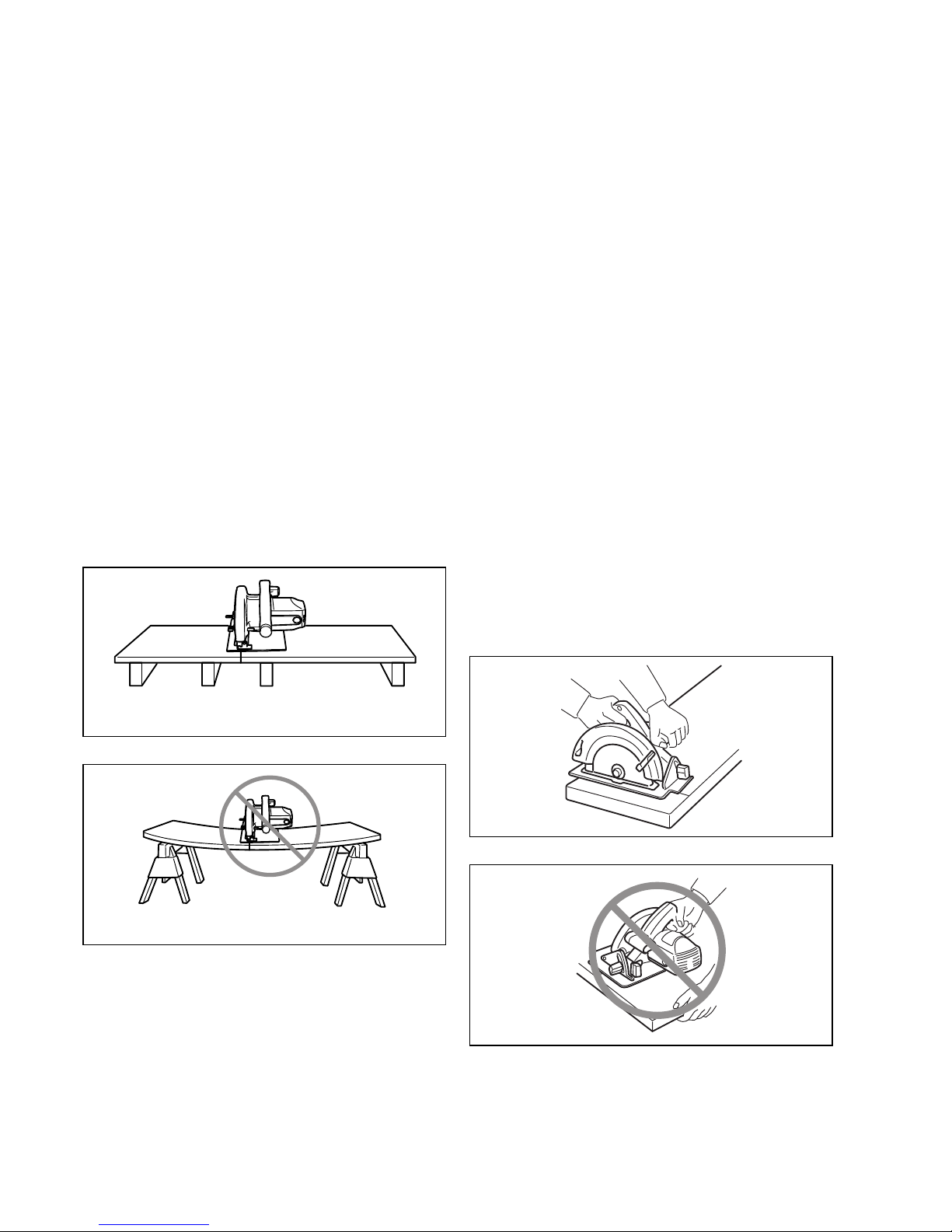
16. Never attempt to saw with the tool held upside
down in a vise. This is extremely dangerous and
can lead to serious accidents.
17. Wear safety goggles and hearing protection dur-
ing operation.
SAVE THESE INSTRUCTION.
FUNCTIONAL DESCRIPTION
CAUTION:
• Always be sure that the tool is switched off and
unplugged before adjusting or checking function on the
tool.
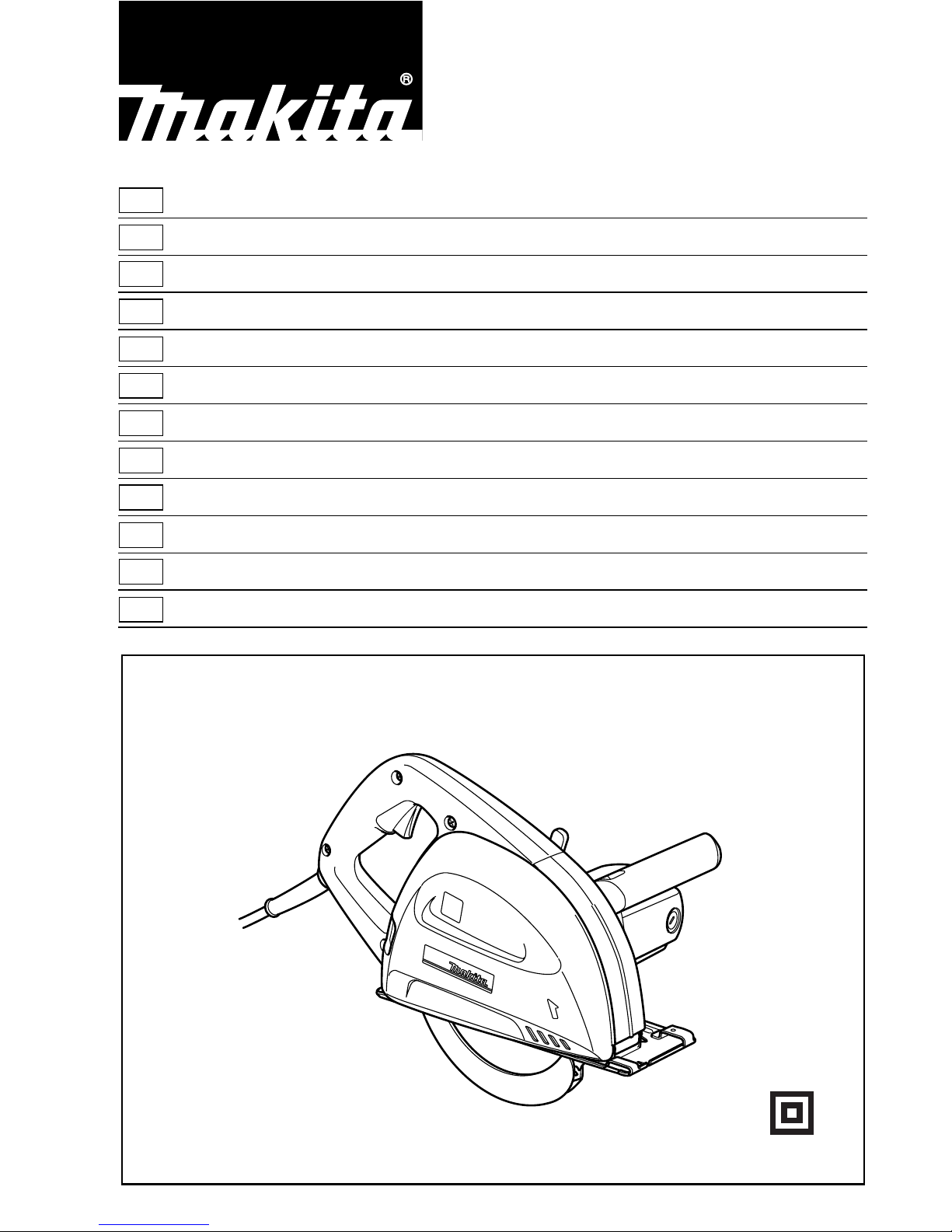
Adjusting the depth of cut (Fig. 1)
Loosen the lever on the depth guide and move the base
up or down. At the desired depth of cut, secure the base
by tightening the lever.
CAUTION:
• After adjusting the depth of cut, always tighten the lever
securely.
Sighting (Fig. 2)
When cutting, align the A position on the front of the base
with your cutting line on the workpiece.
Switch action (Fig. 3)
CAUTION:
• Before plugging in the tool, always check to see that
the switch trigger actuates properly and returns to the
“OFF” position when released.
To prevent the switch trigger from being accidentally
pulled, a lock-off button is provided.
To start the tool, push in the lock-off button and pull the
switch trigger. Release the switch trigger to stop.
ASSEMBLY
CAUTION:
• Always be sure that the tool is switched off and
unplugged before carrying out any work on the tool.
Installing or removing saw blade
CAUTION:
• Use only the Makita wrench provided to install or
remove the blade. Failure to do so may result in over-
tightening or insufficient tightening of the hex bolt. This
could cause serious injury to the operator.
• Do not touch the blade with your bare hand immedi-
ately after cutting, it may be extremely hot and could
burn your skin. Put on pair of gloves when removing a
hot blade.
To remove the blade, first push and turn the knob which
secures the dust cover clockwise to the Osymbol and
remove the dust cover. Press the shaft lock so that the
blade cannot revolve and use the hex wrench to loosen
the hex bolt counterclockwise. Then remove the outer
flange and blade. (Fig. 4 & 5)
To install the blade, follow the removal procedure in
reverse. Always install the blade so that the arrow on the
blade points in the same direction as the arrow on the
blade case.
BE SURE TO TIGHTEN THE HEX BOLT SECURELY.
(Fig. 6)
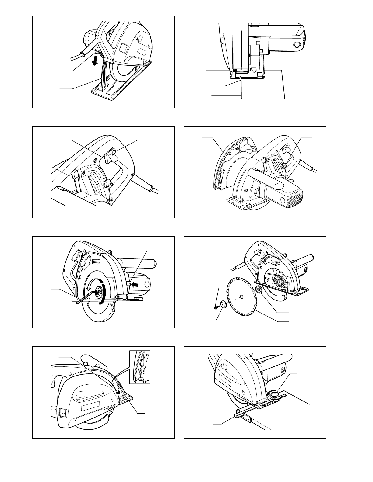
After installing the blade, replace the dust cover. Slide the
dust cover carefully so that the slot of its front fits the rib
of the blade case. Make sure the dust cover fits properly
then push and turn the knob counterclockwise to the z
symbol. (Fig. 7)
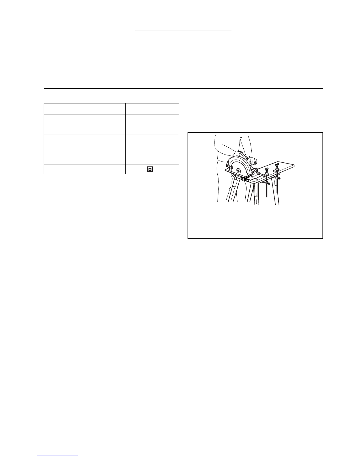
Rip fence (guide rule) (Accessory) (Fig. 8)
The handy rip fence (guide rule) allows you to do extra-
accurate straight cuts. Simply slide the rip fence up
snugly against the side of the workpiece and secure it in
position with the clamp screw on the front of the base. It
also makes repeated cuts of uniform width possible.
OPERATION
CAUTION:
• Never twist or force the tool in the cut. This may cause
motor overload and/or a dangerous kickback, resulting
in serious injury to the operator.
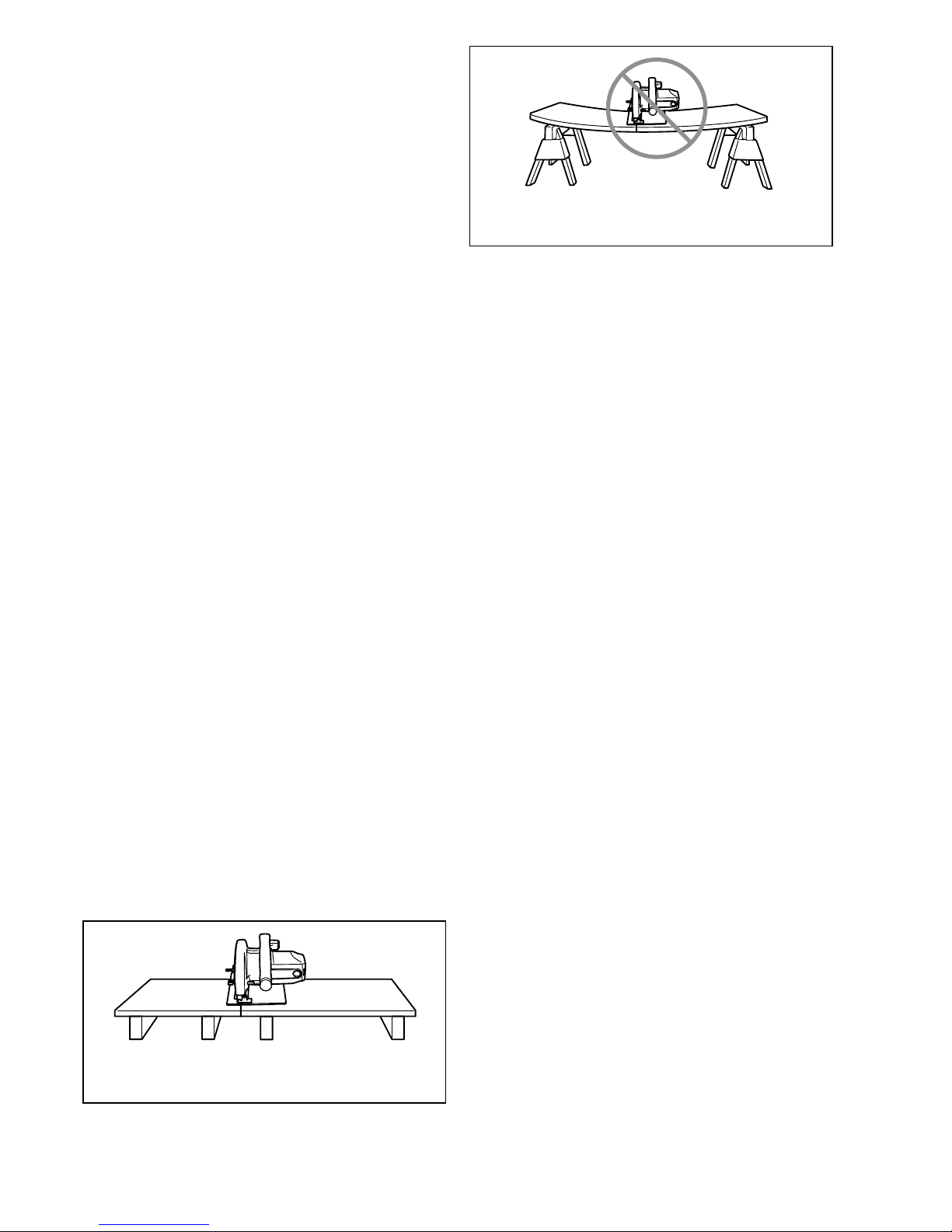
Hold the tool firmly with both hand. Set the base plate on
the workpiece to be cut without the blade making any
contact. Then turn the tool on and wait until the blade
attains full speed. Move the tool forward over the work-
piece surface, keeping it flat and advancing smoothly
until the cutting is completed. Keep your cutting line
straight and your speed of advance uniform. (Fig. 9)
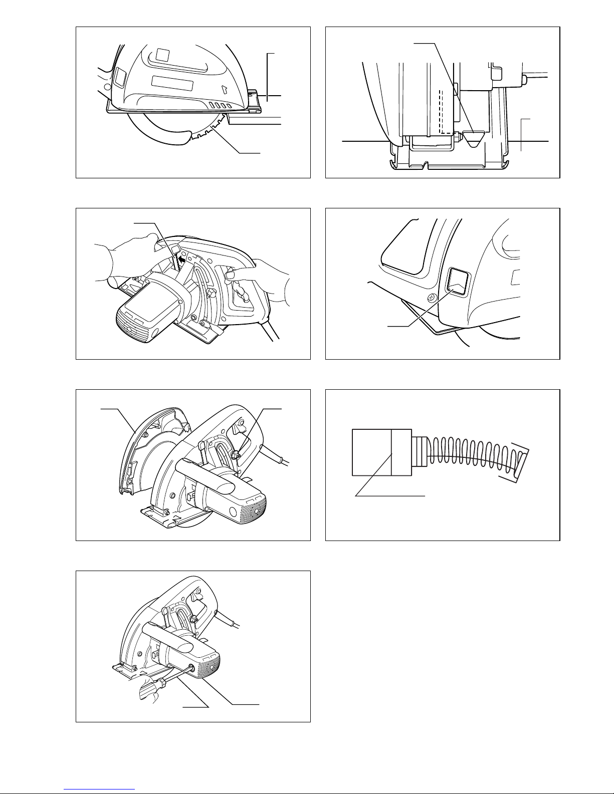
The sight window in the base makes it easy to check the
distance between the front edge of the saw blade and the
workpiece whenever the blade is set to the maximum
depth of cut. (Fig. 10)
NOTE:
• When making a miter cuts etc., sometimes the lower
guard does not move easily. At that time, use the
retracting lever to raise the lower guard for starting cut
and as soon as blade enters the material, release the
retracting lever. (Fig. 11)
CAUTION:
• Do not use a deformed or cracked blade. Replace it
with a new one.
• Do not stack materials when cutting them.
• Do not cut hardened steel, stainless steel, aluminum,
wood, plastics, concrete, tile, etc. Cut only mild steel.
• Do not touch the saw blade, workpiece or cutting chips
with your bare hand immediately after cutting, they may
be extremely hot and could burn your skin.
•Always use the carbide-tipped saw blades appro-
priate for your job. The use of inappropriate saw
blades may cause a poor cutting performance and/or
present a risk of personal injury.
Chip disposal
CAUTION:
• Always be sure that the tool is switched off and
unplugged before removing or installing the dust cover.
• The dust cover may become hot due to hot chips. Do
not touch the cutting chips or dust cover with your bare
hand.
When the cutting chips are visible through the sight win-
dow, dispose of them. (Fig. 12)
Push and turn the knob clockwise to the Osymbol and
remove the dust cover. Dispose of the cutting chips accu-
mulated inside the dust cover. (Fig. 13)

8
CAUTION:
• Do not turn the tool upside down. The cutting chips
accumulated inside the dust cover may fall out of the
dust cover.
• Handle the dust cover carefully so that it will not be
deformed or damaged.
MAINTENANCE
CAUTION:
• Always be sure that the tool is switched off and
unplugged before attempting to perform inspection or
maintenance.
Inspecting saw blade
• Check the blade carefully for cracks or damage before
and after each use. Replace a cracked or damaged
blade immediately.
• Continuing to use a dull blade may cause a dangerous
kickback and/or motor overload. Replace with a new
blade as soon as it no longer cuts effectively.
•Carbide-tipped saw blades for metal cutter cannot
be re-sharpened.
Replacing carbon brushes (Fig. 14 & 15)
Remove and check the carbon brushes regularly.
Replace when they wear down to the limit mark. Keep
the carbon brushes clean and free to slip in the holders.
Both carbon brushes should be replaced at the same
time. Use only identical carbon brushes.
Use a screwdriver to remove the brush holder caps. Take
out the worn carbon brushes, insert the new ones and
secure the brush holder caps.
To maintain product SAFETY and RELIABILITY, repairs,
any other maintenance or adjustment should be per-
formed by Makita Authorized Service Centers, always
using Makita replacement parts.
ACCESSORIES
CAUTION:
• These accessories or attachments are recommended for use with your Makita tool specified in this manual. The use
of any other accessories or attachments might present a risk of injury to persons. Only use accessory or attachment
for its stated purpose.
If you need any assistance for more details regarding these accessories, ask your local Makita service center.
• Rip fence (Guide rule)
• Safety goggle
• Recommended Carbide-tipped saw blades & workpiece ranges
Carbide-Tipped Metal Blades for Many Applications
Excellent Good Fair Not Applicable
CAUTION:
• Always use carbide-tipped saw blades appropriate for your job. Do not cut aluminum, wood, plastics, concrete, tiles,
etc.
• Carbide-tipped saw blades for metal cutting saw are not to be resharpened.
Applications
METAL SHEET C-STUD ANGLE-STUD METAL STUD REBAR PIPE CORRUGATED
SHEET
Size (mm) t=1.5 t=3.0 50x100
t=1.6
45x90
t=3.2
50x50
t=4
50x50
t=6
t=0.56
25Ga
t=1.6
16Ga ∅20 50x100
t=3.2 ∅25
t=1.2 ∅60
t=3.8 t=0-0.9 t=1.0-
2.0
185x36T
185x38T
185x48T
185x70T

23
NEDERLANDS
Verklaring van algemene gegevens
1 Hendel
2 Dieptegeleider
3 Zaaglijn
4 Trekschakelaar
5 Ontgrendelknop
6 Stofkap
7 Knop
8 Dopsleutel
9 Asblokkering
10 Zeskantbout
11 Buitenflens
12 Zaagblad met hardmetalen
tanden
13 Binnenflens
14 Sleuf
15 Ribbe
16 Trekgeleider (breedtegeleider)
17 Schroef
18 Werkstuk
19 Kijkglas
20 Terugtrekhendel
21 Limietaanduiding
22 Schroevendraaier
23 Borstelhouderdop
TECHNISCHE GEGEVENS
• In verband met ononderbroken research en ontwikke-
ling behouden wij ons het recht voor bovenstaande
technische gegevens te wijzigen zonder voorafgaande
kennisgeving.
• Opmerking: De technische gegevens kunnen van land
tot land verschillen.
Doeleinden van gebruik
Dit gereedschap is bestemd voor het zagen van zacht
staal.
Stroomvoorziening
Het gereedschap mag alleen worden aangesloten op
een stroombron van hetzelfde voltage als aangegeven op
de naamplaat, en kan alleen op enkel-fase wisselstroom
worden gebruikt. Het gereedschap is dubbel-geïsoleerd
volgens de Europese standaard en kan derhalve ook op
een niet-geaard stopcontact worden aangesloten.
Veiligheidswenken
Voor uw veiligheid dient u de bijgevoegde Veiligheids-
voorschriften nauwkeurig op te volgen.
AANVULLENDE
VEILIGHEIDSVOORSCHRIFTEN VOOR HET
GEREEDSCHAP
GEVAAR:
1. Houd uw handen uit de buurt van de zaagomge-
ving en het zaagblad. Houd uw tweede hand op
de hulphandgreep of op het motorhuis. Als u het
gereedschap met beide handen vasthoudt, is er
geen gevaar voor verwonding door het zaagblad.
2. Reik niet onder het werkstuk. De beschermkap
biedt geen bescherming tegen het zaagblad onder
het werkstuk.
3. Stel de zaagdiepte af in overeenstemming met
de dikte van het werkstuk. Niet meer dan een volle
tand van de zaagbladtanden mag onder het werk-
stuk zichtbaar zijn.
4. Zaag nooit met het werkstuk in uw hand of op uw
dijen geplaatst. Zet het werkstuk vast op een sta-
biele werktafel. Het is belangrijk dat het werkstuk
op de juiste manier wordt ondersteund om gevaar
voor verwonding, klemming van het zaagblad, of
controleverlies tot een minimum te beperken.
5. Houd elektrisch gereedschap altijd vast bij de
geïsoleerde handgreepoppervlakken wanneer er
kans is dat het zaagblad met verborgen bedra-
ding of zijn eigen stroomkabel in contact kan
komen. Door contact met een onder spanning
staande draad komen ook de blote metalen delen
van het elektrisch gereedschap onder spanning te
staan zodat er gevaar is voor een elektrische schok.
6. Gebruik voor het schulpen altijd een breedtege-
leider of een richtliniaal. De snede zal dan nauw-
keuriger zijn en er is minder kans dat het zaagblad
klemt.
7. Gebruik altijd zaagbladen met asgaten van de
juiste grootte en vorm (diamant of rond). Zaag-
bladen die niet precies passen op de montagehard-
ware van het gereedschap zullen excentrisch
draaien, zodat er gevaar is voor controleverlies.
8. Gebruik nooit defecte of onjuiste sluitringen of
bouten. De sluitringen en bout van het zaagblad zijn
speciaal ontworpen met het oog op optimale presta-
ties en veilige bediening van uw gereedschap.
9. Oorzaken van en voorzorgsmatregelen tegen
terugslag;
• Terugslag is een plotselinge reactie, veroor-
zaakt door een geklemd, geblokkeerd of slecht
uitgelijnd zaagblad, waardoor het gereedschap
uit het werkstuk naar omhoog wordt gedreven
en naar de gebruiker wordt teruggeslagen.
Model 4131
Diameter zaagblad 185 mm
Max. zaagcapaciteit 63 mm
Toerental onbelast (min–1)3500
Totale lengte 358 mm
Netto gewicht 4,8 kg
Veiligheidsklasse /II
De afbeelding toont een typisch voorbeeld van de
juiste manier voor het vasthouden van het gereed-
schap, het ondersteunen van het werkstuk, en het
plaatsen van de stroomkabel (indien voorzien).

24
• Indien het zaagblad in de zaagsnede vastge-
kneld of geklemd raakt, zal het zaagblad blok-
keren en wordt de zaag door de motorreactie
plotseling naar de gebruiker teruggeslagen.
• Indien het zaagblad gewrongen of gebogen in
de snede zit, kunnen de tanden op het achter-
einde van het zaagblad in het bovenoppervlak
van het werkstuk snijden, zodat het zaagblad
uit de zaagsnede naar omhoog wordt gedreven
en naar de gebruiker wordt teruggeslagen.
Terugslag is het gevolg van verkeerd gebruik en/
of verkeerde bedieningen of gebruikscondities
van het gereedschap. Terugslag kan worden
voorkomen door de onderstaande voorzorgs-
maatregelen in acht te nemen.
a. Houd het gereedschap stevig vast met beide
handen op het gereedschap geplaatst, en
houd uw armen zodanig dat ze kunnen weer-
staan aan eventuele terugslag. Ga aan een
van beide zijden van het zaagblad staan, en
nooit vlak achter het zaagblad. Bij terugslag
kan het gereedschap naar achteren worden
teruggeslagen, maar door de nodige voorzorgen
te nemen kan de gebruiker weerstaan aan de
kracht van de terugslag.
b. Wanneer het zaagblad klemt, of wanneer u
het zagen even wilt onderbreken, laat dan de
trekschakelaar los en houd het gereedschap
onbeweeglijk in het materiaal totdat het zaag-
blad tot volledige stilstand is gekomen. Pro-
beer nooit om het zaagblad uit het werkstuk
te verwijderen of het gereedschap naar ach-
teren te trekken terwijl het zaagblad nog
beweegt, omdat er dan gevaar is voor terug-
slag. Zoek de oorzaak van de blokkering van het
zaagblad en neem de nodige maatregelen om
het probleem te verhelpen.
c. Wanneer u het gereedschap in het werkstuk
opnieuw start, moet u het zaagblad goed in
de snede centreren en controleren of de
zaagtanden niet in het materiaal dringen.
Indien het zaagblad klemt, kan het bij het
opnieuw opstarten uit het werkstuk worden
gedreven of terugslaan.
d. Ondersteun grote panelen om de kans op
klemmen en terugslaan van het zaagblad tot
een minimum te beperken. Grote panelen heb-
ben de neiging om onder hun eigen gewicht door
te buigen. Plaats steunen onder het paneel aan
beide zijden van het gereedschap, dicht bij de
zaaglijn en dicht bij de buitenrand van het
paneel.
e. Gebruik geen onscherpe of beschadigde
zaagbladen. Onscherpe of slecht gemonteerde
zaagbladen produceren een smalle zaagsnede,
hetgeen overmatige wrijving, klemming van het
zaagblad en terugslag tot gevolg kan hebben.
f. De hendels voor afstelling van de zaagblad-
diepte en de verstekhoek moeten goed vast-
gezet zijn voordat u gaat zagen. Er is gevaar
voor klemming van het zaagblad en terugslag
indien de afstelling van het zaagblad tijdens het
zagen verschuift.
10. Controleer voor elk gebruik of de onderste
beschermkap goed sluit. Gebruik het gereed-
schap niet indien de onderste beschermkap niet
vrij beweegt en niet ogenblikkelijk sluit. Klem of
bind de onderste beschermkap nooit in de geo-
pende stand vast. Als u het gereedschap hebt laten
vallen, kan de onderste beschermkap verbogen zijn.
Breng de onderste beschermkap omhoog met de
terugtrekhendel en controleer of deze onbelemmerd
beweegt en bij alle zaaghoeken en zaagdieptes niet
in aanraking komt met het zaagblad of een ander
onderdeel.
11. Controleer de werking van de veer van de onder-
ste beschermkap. Indien de beschermkap en de
veer niet behoorlijk werken, dient u deze te repa-
reren vóór het gebruik. De onderste beschermkap
kan stug bewegen ten gevolge van beschadigde
onderdelen, aangezette lijm of opbouw van vuil.
12. Controleer altijd of de onderste beschermkap
het zaagblad afschermt alvorens het gereed-
schap op de werkbank of vloer te plaatsen. Als
het zaagblad nog draait en niet is afgeschermd, zal
het gereedschap achterwaarts bewegen en alles op
zijn weg doorsnijden.
13. Stop het zaagblad niet door er zijwaartse druk op
uit te oefenen.
14. GEVAAR:
Probeer niet om afgezaagde stukken te verwijde-
ren terwijl het zaagblad nog draait.
LET OP:
Nadat de zaag is uitgeschakeld, blijft het zaag-
blad nog een tijdje ronddraaien.
Ondersteun de plank of het paneel dicht bij de
zaaglijn, om terugslag te voorkomen.
Plaats de steunen van de plank of het paneel
niet ver weg van de zaaglijn.

25
15. Plaats het bredere deel van de zaagvoet op het
gedeelte van het werkstuk dat stevig onder-
steund is, en niet op het gedeelte dat eraf zal val-
len wanneer het zagen voltooid is.
Fig. A toont de JUISTE manier om het uiteinde
van een plank af te zagen. Fig. B toont de
ONJUISTE manier. Indien het werkstuk kort of
klein is, klem het dan vast. PROBEER NIET OM
KORTE WERKSTUKKEN MET UW HAND VAST
TE HOUDEN! (Fig. B)
Fig. A
Fig. B
16. Probeer nooit om te zagen met het gereedschap
ondersteboven in een schroefbank vastgezet. Dit
is uiterst gevaarlijk en kan ernstige ongelukken
veroorzaken.
17. Draag tijdens het gebruik een veiligheidsbril en
oorbeschermers.
BEWAAR DEZE VOORSCHRIFTEN.
BESCHRIJVING VAN DE FUNCTIES
LET OP:
• Zorg altijd dat het gereedschap is uitgeschakeld en niet
op een stopcontact is aangesloten voordat u functies
op het gereedschap instelt of controleert.
Instellen van de zaagdiepte (Fig. 1)
Draai de hendel op de dieptegeleider los en beweeg de
voetplaat naar boven of naar beneden. Zet de voetplaat
bij de gewenste diepte weer vast door de hendel vast te
draaien.
LET OP:
• Draai de hendel altijd stevig vast nadat de zaagdiepte
is ingesteld.
Richten (Fig. 2)
Voordat u gaat zagen, dient u de inkeping A op de voor-
kant van de voetplaat op één lijn te brengen met de
zaaglijn op het werkstuk.
Werking van de trekschakelaar (Fig. 3)
LET OP:
• Alvorens het gereedschap op een stopcontact aan te
sluiten, moet u altijd controleren of de trekschakelaar
behoorlijk werkt en bij het loslaten naar de “OFF” posi-
tie terugkeert.
Een ontgrendelknop is voorzien om te voorkomen dat de
trekschakelaar per toeval wordt ingedrukt.
Om het gereedschap te starten, drukt u eerst de ontgren-
delknop in en daarna de trekschakelaar. Laat de trek-
schakelaar los om het gereedschap te stoppen.
INEENZETTEN
LET OP:
• Zorg altijd dat het gereedschap is uitgeschakeld en niet
op een stopcontact is aangesloten alvorens enig werk
aan het gereedschap uit te voeren.
Installeren of verwijderen van het zaagblad
LET OP:
• Gebruik voor het installeren of verwijderen van het
zaagblad uitsluitend de meegeleverde Makita dopsleu-
tel. Doet u dit niet, dan kan de zeskantbout te vast of te
los worden aangedraaid, hetgeen kan leiden tot ver-
wonding van de gebruiker.
• Raak het zaagblad niet met uw blote hand aan onmid-
dellijk na het zagen. Het blad kan zeer heet zijn en
brandwonden veroorzaken. Trek een paar handschoe-
nen aan om een nog heet zaagblad te verwijderen.
Om het zaagblad te verwijderen, druk eerst de vastzet-
knop van de stofkap in en draai hem naar rechts naar het
Osymbool, en verwijder de stofkap. Druk de asblokke-
ring in zodat het zaagblad niet kan draaien, en draai met
de dopsleutel de zeskantbout naar links los. Verwijder
vervolgens de buitenflens en het zaagblad. (Fig. 4 en 5)
Om het zaagblad te installeren, voert u de verwijderings-
procedure in omgekeerde volgorde uit. Monteer het
zaagblad altijd zodanig dat het pijltje op het zaagblad in
dezelfde richting wijst als het pijltje op de zaagbladkast.
TREK DE ZESKANTBOUT STEVIG AAN. (Fig. 6)
Breng de stofkap weer aan nadat het zaagblad is geïn-
stalleerd. Schuif de stofkap voorzichtig erin zodat de
sleuf op de voorzijde ervan in de ribbe van de zaagblad-
kast past. Controleer of de stofkap goed gemonteerd is
en druk daarna de knop in en draai hem naar rechts naar
het zsymbool. (Fig. 7)
Trekgeleider (breedtegeleider) (Accessoire)
(Fig. 8)
De handige trekgeleider (breedtegeleider) maakt het
mogelijk uiterst nauwkeurige rechte zaagsneden te
maken. Plaats de trekgeleider vlak tegen de zijkant van
het werkstuk en zet hem vervolgens vast met de klem-
schroef op de voorkant van de voetplaat. Met de trekge-
leider kunt u ook herhaaldelijk stukken van gelijke
breedte afzagen.

26
BEDIENING
LET OP:
• Forceer of wring het zaagblad nooit in de zaagsnede.
Dit kan overbelasting van de motor en/of gevaarlijke
terugslag veroorzaken, met ernstige verwonding van
de gebruiker als mogelijk gevolg.
Houd het gereedschap stevig vast met beide handen. Zet
de voetplaat op het te zagen werkstuk zonder dat het
zaagblad ermee in contact komt. Schakel vervolgens het
gereedschap in en wacht totdat het zaagblad op volle
snelheid draait. Beweeg dan het gereedschap naar voren
over het oppervlak van het werkstuk; houd hierbij het
gereedschap vlak en beweeg het langzaam totdat het
zagen is voltooid. Houd de zaaglijn recht en beweeg het
gereedschap met gelijkmatige snelheid naar voren.
(Fig. 9)
Gebruik het vizier in de voetplaat om de afstand tussen
de voorrand van het zaagblad en het werkstuk te contro-
leren telkens wanneer het zaagblad op de maximale
zaagdiepte is ingesteld. (Fig. 10)
OPMERKING:
• Bij verstekzagen e.d., is het mogelijk dat de onderste
beschermkap niet gemakkelijk beweegt. Gebruik in dat
geval de terugtrekhendel om de onderste beschermkap
omhoog te brengen en het zagen te starten. Laat de
terugtrekhendel los zodra het zaagblad in het materiaal
dringt. (Fig. 11)
LET OP:
• Gebruik nooit een vervormd of gebarsten zaagblad.
Vervang het door een nieuw zaagblad.
• Stapel de te zagen werkstukken niet op elkaar.
• Gebruik de zaag niet voor het zagen van gehard staal,
roestvrij staal, aluminium, hout, kunststoffen, beton,
tegels, e.d. Gebruik de zaag uitsluitend voor het
zagen van zacht staal.
• Raak het zaagblad, het werkstuk of de spanen niet aan
met uw blote hand onmiddellijk na het zagen. Deze
kunnen zeer heet zijn en brandwonden veroorzaken.
•Gebruik altijd zaagbladen met hardmetalen tanden
die geschikt zijn voor uw werk. Het gebruik van
ongeschikte zaagbladen kan leiden tot slechte zaag-
prestaties en/of gevaar voor persoonlijke verwonding.
Verwijderen van zaagspanen
LET OP:
• Zorg altijd dat het gereedschap is uitgeschakeld en zijn
stroomkabel uit het stopcontact is verwijderd alvorens
de stofkap te verwijderen of te installeren.
• De stofkap kan heet worden ten gevolge van hete
zaagspanen. Raak de zaagspanen of de stofkap niet
met blote handen aan.
Verwijder de zaagspanen wanneer deze door het kijkglas
te zien zijn. (Fig. 12)
Druk de knop in en draai hem naar rechts naar het sym-
bool O, en verwijder de stofkap. Verwijder de zaagspa-
nen uit de stofkap. (Fig. 13)
LET OP:
• Keer het gereedschap niet ondersteboven. Als u dit
doet, kunnen de opeengehoopte zaagspanen uit de
stofkap vallen.
• Behandel de stofkap voorzichtig om vervorming of
beschadiging ervan te voorkomen.
ONDERHOUD
LET OP:
• Zorg altijd dat het gereedschap is uitgeschakeld en niet
op een stopcontact is aangesloten voordat u begint met
inspectie of onderhoud.
Inspecteren van het zaagblad
• Inspecteer het zaagblad zorgvuldig op barsten of
beschadiging vóór en na elk gebruik. Vervang een
gebarsten of beschadigd zaagblad onmiddellijk.
• Voortgezet gebruik met een bot zaagblad kan gevaar-
lijke terugslag en/of overbelasting van de motor veroor-
zaken. Vervang door een nieuw zaagblad zodra u
vaststelt dat het zaagblad niet meer goed snijdt.
• Zaagbladen met hardmetalen tanden voor metaal-
zagen kunnen niet opnieuw gescherpt worden.
Vervangen van de koolborstels (Fig. 14 en 15)
Verwijder en controleer regelmatig de koolborstels. Ver-
vang de koolborstels wanneer ze tot aan de limietmarke-
ring versleten zijn. Houd de koolborstels schoon zodat ze
goed in de houders glijden. Beide koolborstels dienen
tegelijkertijd te worden vervangen. Gebruik uitsluitend
identieke koolborstels.
Gebruik een schroevendraaier om de doppen van de
koolborstelhouders te verwijderen. Haal de versleten bor-
stels eruit, steek de nieuwe erin, en zet de doppen weer
goed vast.
Om de VEILIGHEID en BETROUWBAARHEID van het
product te handhaven, dienen alle reparaties en alle
andere onderhoudswerkzaamheden of afstellingen te
worden uitgevoerd door een erkend Makita Servicecen-
trum, en dat uitsluitend met gebruik van Makita vervan-
gingsonderdelen.

27
ACCESSOIRES
LET OP:
• Deze accessoires of hulpstukken worden aanbevolen voor gebruik met het Makita gereedschap dat in deze
gebruiksaanwijzing is beschreven. Bij gebruik van andere accessoires of hulpstukken bestaat er gevaar voor per-
soonlijke verwonding. Gebruik de accessoires of hulpstukken uitsluitend voor hun bestemd doel.
Wenst u meer bijzonderheden over deze accessoires, neem dan contact op met het plaatselijke Makita servicecen-
trum.
• Trekgeleider (breedtegeleider)
• Veiligheidsbril
• Aanbevolen zaagbladen met hardmetalen tanden & afmetingen van het werkstuk
Hardmetalen zaagbladen voor allerlei toepassingen
Uitstekend Goed Bevredigend Niet toepasselijk
LET OP:
• Gebruik altijd zaagbladen met hardmetalen tanden die geschikt zijn voor uw werk. Gebruik de zaag niet voor het
zagen van aluminium, hout, kunststoffen, beton, tegels, e.d.
• Zaagbladen met hardmetalen tanden voor metaalzagen kunnen niet opnieuw gescherpt worden.
Toepassingen
BLADMETAAL C-TAPEIND HOEKTAPEIND METALEN
TAPEIND
STALEN
STAAF PIJP GEGOLFDE
STAALPLAAT
Afmeting
(mm) t=1,5 t=3,0 50x100
t=1,6
45x90
t=3,2
50x50
t=4
50x50
t=6
t=0,56
25Ga
t=1,6
16Ga ∅20 50x100
t=3,2 ∅25
t=1,2 ∅60
t=3,8 t=0-0,9 t=1,0-
2,0
185x36T
185x38T
185x48T
185x70T

60
ENH101-3
EC-DECLARATION OF CONFORMITY
We declare under our sole responsibility that this product
is in compliance with the following standards of standard-
ized documents,
EN60745, EN55014, EN61000
in accordance with Council Directives, 73/23/EEC,
89/336/EEC and 98/37/EC.
DÉCLARATION DE CONFORMITÉ CE
Nous déclarons sous notre entière responsabilité que ce
produit est conforme aux normes des documents stan-
dardisés suivants,
EN60745, EN55014, EN61000
conformément aux Directives du Conseil, 73/23/CEE,
89/336/CEE et 98/37/EG.
CE-KONFORMITÄTSERKLÄRUNG
Hiermit erklärt wir unter unserer alleinigen Verantwor-
tung, daß dieses Produkt gemäß den Ratsdirektiven
73/23/EWG, 89/336/EWG und 98/37/EG mit den fol-
genden Normen von Normendokumenten übereinstim-
men:
EN60745, EN55014, EN61000.
DICHIARAZIONE DI CONFORMITÀ
CON LE NORME DELLA COMUNITÀ EUROPEA
Dichiariamo sotto la nostra sola responsabilità che
questo prodotto è conforme agli standard di documenti
standardizzati seguenti:
EN60745, EN55014, EN61000
secondo le direttive del Consiglio 73/23/CEE, 89/336/CEE e
98/37/CE.
EG-VERKLARING VAN CONFORMITEIT
Wij verklaren hierbij uitsluitend op eigen verant-
woordelijkheid dat dit produkt voldoet aan de volgende
normen van genormaliseerde documenten,
EN60745, EN55014, EN61000
in overeenstemming met de richtlijnen van de Raad
73/23/EEC, 89/336/EEC en 98/37/EC.
DECLARACIÓN DE CONFORMIDAD DE LA CE
Declaramos bajo nuestra sola responsabilidad que este
producto cumple con las siguientes normas de docu-
mentos normalizados,
EN60745, EN55014, EN61000
de acuerdo con las directivas comunitarias, 73/23/EEC,
89/336/EEC y 98/37/CE.
Yasuhiko Kanzaki
CE 2004
Director Amministratore
Directeur Directeur
Direktor Director
MAKITA INTERNATIONAL EUROPE LTD.
Michigan Drive, Tongwell, Milton Keynes,
Bucks MK15 8JD, ENGLAND
Responsible manufacturer: Produttore responsabile:
Fabricant responsable :Verantwoordelijke fabrikant:
Verantwortlicher Hersteller: Fabricante responsable:
Makita Corporation Anjo Aichi Japan
ENGLISH
FRANÇAISE
DEUTSCH
ITALIANO
NEDERLANDS
ESPAÑOL

61
ENH101-3
DECLARAÇÃO DE CONFORMIDADE DA CE
Declaramos sob inteira responsabilidade que este
produto obedece às seguintes normas de documentos
normalizados,
EN60745, EN55014, EN61000
de acordo com as directivas 73/23/CEE, 89/336/CEE e
98/37/CE do Conselho.
EU-DEKLARATION OM KONFORMITET
Vi erklærer hermed påeget ansvar, at dette produkt er i
overensstemmelse med de følgende standarder i de norm-
sættende dokumenter,
EN60745, EN55014, EN61000
i overensstemmelse med Rådets Direktiver 73/23/EEC,
89/336/EEC og 98/37/EC.
EG-DEKLARATION OM ÖVERENSSTÄMMELSE
Under eget ansvar deklarerar vi härmed att denna
produkt överensstämmer med följande standardiseringar
för standardiserade dokument,
EN60745, EN55014, EN61000
i enlighet med EG-direktiven 73/23/EEC, 89/336/EEC
och 98/37/EC.
EUs SAMSVARS-ERKLÆRING
Vi erklærer påeget ansvar at dette produktet er i over-
ensstemmelse med følgende standard i de standardis-
erte dokumenter:
EN60745, EN55014, EN61000,
i samsvar med Råds-direktivene, 73/23/EEC,
89/336/EEC og 98/37/EC.
VAKUUTUS EC-VASTAAVUUDESTA
Yksinomaisesti vastuullisina ilmoitamme, ettätämätuote
on seuraavien standardoitujen dokumenttien standar-
dien mukainen,
EN60745, EN55014, EN61000
neuvoston direktiivien 73/23/EEC, 89/336/EEC ja
98/37/EC mukaisesti.
∆ΗΛΩΣΗ ΣΥΜΜΟΡΦΩΣΗΣ ΕΚ
∆ηλώνουµε υπ την µοναδική µας ευθύνη τι αυτ
το προιν βρίσκεται σε Συµφωνία µε τα ακλουθα
πρτυπα τυποποιηµένων εγγράφων
EN60745, EN55014, EN61000
σύµφωνα µε τις Οδηγίες του Συµβουλίου
73/23/EEC 89/336/EEC και 98/37/ΚE.
Yasuhiko Kanzaki
CE 2004
Director Direktor
DirektørJohtaja
Direktör∆ιευθυντής
Müdür
MAKITA INTERNATIONAL EUROPE LTD.
Michigan Drive, Tongwell, Milton Keynes,
Bucks MK15 8JD, ENGLAND
Fabricante responsável: Ansvarlig produsent:
Ansvarlig fabrikant: Vastaava valmistaja:
Ansvarig tillverkare: Υπεύθυνος κατασκευαστής:
Makita Corporation Anjo Aichi Japan
PORTUGUÊS
DANSK
SVENSKA
NORSK
SUOMI
ΕΛΛΗΝΙΚΑ

62
ENG005-2
For European countries only
Noise and Vibration
The typical A-weighted noise levels are
sound pressure level: 99 dB (A)
sound power level: 110 dB (A)
Uncertainty is 3 dB (A).
–Wear ear protection. –
The typical weighted root mean square acceleration
value is not more than 2.5 m/s2.
These values have been obtained according to
EN60745.
Pour les pays d’Europe uniquement
Bruit et vibrations
Les niveaux de bruit ponderes types A sont:
niveau de pression sonore: 99dB (A)
niveau de puissance du son: 110 dB (A)
L’incertitude de mesure est de 3 dB (A).
–Porter des protecteurs anti-bruit. –
L’accélération pondérée ne dépasse pas 2,5 m/s2.
Ces valeurs ont étéobtenues selon EN60745.
Nur für europäische Länder
Geräusch- und Vibrationsentwicklung
Die typischen A-bewerteten Geräuschpegel betragen:
Schalldruckpegel: 99 dB (A)
Schalleistungspegel: 110 dB (A)
Die Abweichung beträgt 3 dB (A).
–Gehörschutz tragen. –
Der gewichtete Effektivwert der Beschleunigung beträgt
nicht mehr als 2,5 m/s2.
Diese Werte wurden gemäß EN60745 erhalten.
Modello per l’Europa soltanto
Rumore e vibrazione
I livelli del rumore pesati secondo la curva A sono:
Livello pressione sonora: 99 dB (A)
Livello potenza sonora: 110 dB (A)
L’incertezza èdi 3 dB (A).
–Indossare i paraorecchi. –
Il valore quadratico medio di accellerazione non supera i
2,5 m/s2.
Questi valori sono stati ottenuti in conformitàEN60745.
Alleen voor Europese landen
Geluidsniveau en trilling
De typische A-gewogen geluidsniveau’s zijn
geluidsdrukniveau: 99 dB (A)
geluidsenergie-niveau: 110 dB (A)
Onzekerheid is 3 dB (A).
–Draag oorbeschermers. –
De typische gewogen effectieve versnellingswaarde is
niet meer dan 2,5 m/s2.
Deze waarden werden verkregen in overeenstemming
met EN60745.
Para países europeos solamente
Ruido y vibración
Los niveles típicos de ruido ponderados A son
presión sonora: 99 dB (A)
nivel de potencia sonora: 110 dB (A)
Incerteza 3 dB (A).
–Póngase protectores en los oídos. –
El valor ponderado de la aceleración no sobrepasa los
2,5 m/s2.
Estos valores han sido obtenidos de acuerdo con
EN60745.
ENGLISH
FRANÇAISE
DEUTSCH
ITALIANO
NEDERLANDS
ESPAÑOL

63
ENG005-2
Só para países Europeus
Ruído e vibração
Os níveis normais de ruído A são
nível de pressão de som: 99 dB (A)
nível do sum: 110 dB (A)
A incerteza é de 3 dB (A).
– Utilize protectores para os ouvidos –
O valor médio da aceleração é inferior a 2,5 m/s2.
Estes valores foram obtidos de acordo com EN60745.
Kun for lande i Europa
Lyd og vibration
De typiske A-vægtede lydniveauer er
lydtryksniveau: 99 dB (A)
lydeffektniveau: 110 dB (A)
Der er en usikkerhed på 3 dB (A).
– Bær høreværn. –
Den vægtede effektive accelerationsværdi overstiger ikke
2,5 m/s2.
Disse værdier er beregnet i overensstemmelse med
EN60745.
Endast för Europa
Buller och vibration
De typiska A-vägda bullernivåerna är
ljudtrycksnivå: 99 dB (A)
ljudeffektnivå: 110 dB (A)
Osäkerheten är 3 dB (A).
– Använd hörselskydd –
Det typiskt vägda effektivvärdet för acceleration översti-
ger inte 2,5 m/s2.
Dessa värden har erhållits i enlighet med EN60745.
Gjelder bare land i Europa
Støy og vibrasjon
De vanlige A-belastede støynivå er
lydtrykksnivå: 99 dB (A)
lydstyrkenivå: 110 dB (A)
Usikkerheten er på 3 dB (A).
– Benytt hørselvern. –
Den vanlig belastede effektiv-verdi for akselerasjon over-
skrider ikke 2,5 m/s2.
Disse verdiene er beregnet eller målt i samsvar med
EN60745.
Vain Euroopan maat
Melutaso ja tärinä
Tyypilliset A-painotetut melutasot ovat
äänenpainetaso: 99 dB (A)
äänen tehotaso: 110 dB (A)
Epävarmuus on 3 dB (A).
– Käytä kuulosuojaimia. –
Tyypillinen kiihtyvyyden painotettu tehollisarvo ei ylitä
2,5 m/s2.
Nämä arvot on mitattu normin EN60745 mukaisesti.
Μνο για χώρες της Ευρώπης
Θρυβος και κραδασµς
Οι τυπικές A-µετρούµενες εντάσεις ήχου είναι
πίεση ήχου: 99 dB (A)
δύναµη του ήχου: 0 dB (A)
Η Αβεβαι%τητα είναι 3 dB (A).
– Φοράτε ωτοασπίδες. –
Η τυπική αξία της µετρούµενης ρίζας του µέσου
τετραγώνου της επιτάχυνσης δεν ξεπερνά τα
2,5 m/s2.
Αυτές οι τιµές έχουν σηµειωθεί σύµφωνα µε το
EN60745.
PORTUGUÊS
DANSK
SVENSKA
NORSK
SUOMI
ΕΛΛΗΝΙΚΑ

Makita Corporation
Anjo, Aichi, Japan
884543C995
Other manuals for 4131
1
Table of contents
Languages:
Other Makita Cutter manuals

Makita
Makita 4105KB User manual

Makita
Makita 4100NH2X User manual

Makita
Makita 3803A User manual

Makita
Makita CS002GZ01 User manual

Makita
Makita DCO140 User manual

Makita
Makita EK7301 Instruction Manual

Makita
Makita 4112HS User manual

Makita
Makita BCS550 User manual

Makita
Makita CC301D User manual

Makita
Makita 4112H Quick start guide

Makita
Makita BCS550 User manual

Makita
Makita PC01 User manual

Makita
Makita SC103D User manual

Makita
Makita BCS550 User manual

Makita
Makita CE002G User manual

Makita
Makita CA5000 User manual

Makita
Makita 4131 User manual

Makita
Makita DSC163 User manual

Makita
Makita DCS553 User manual

Makita
Makita XEC01 Series User manual