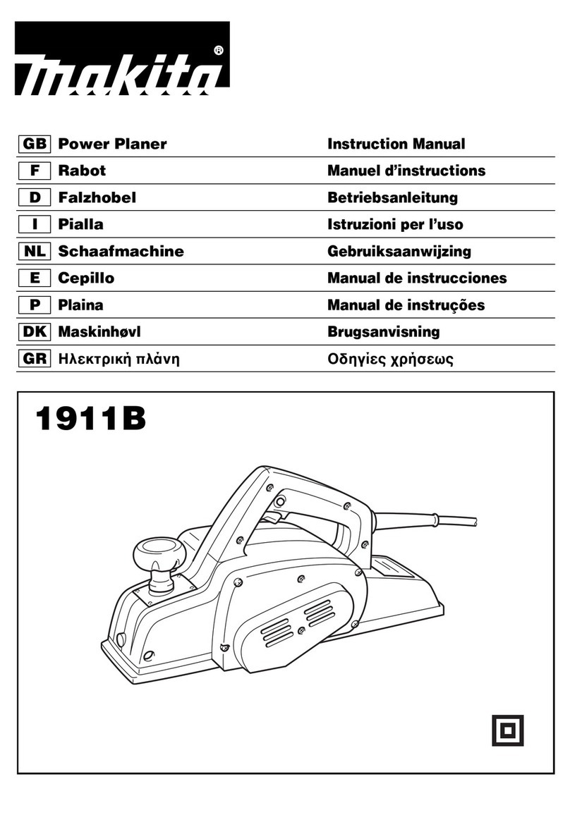
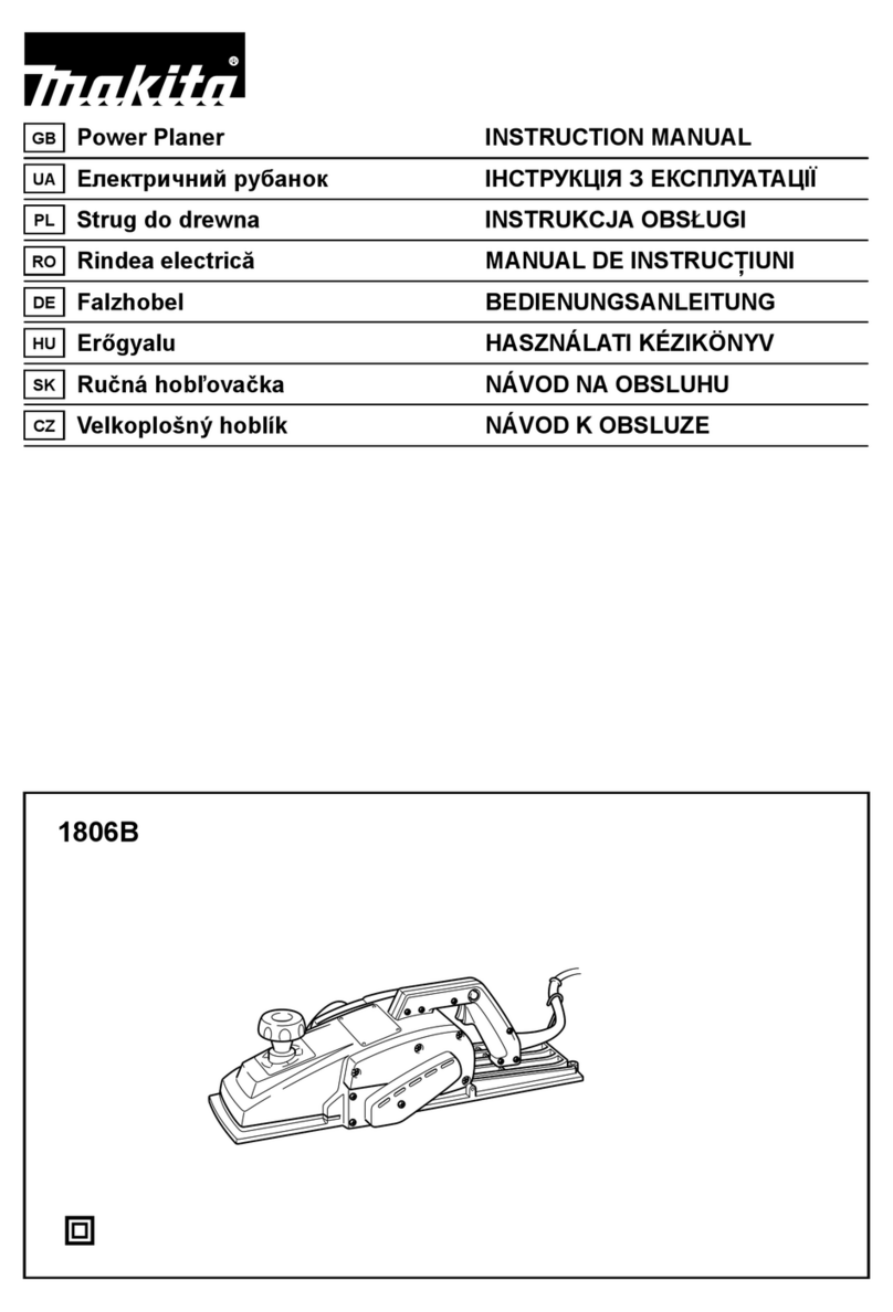
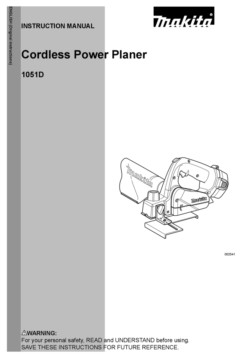
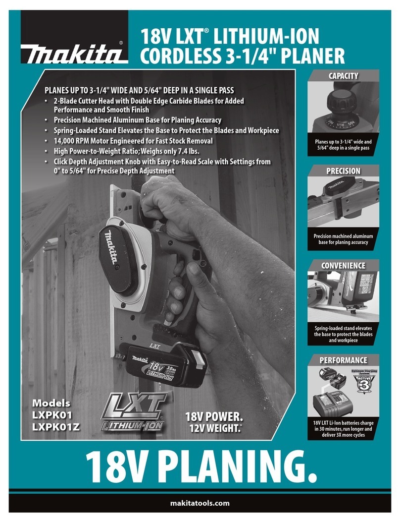
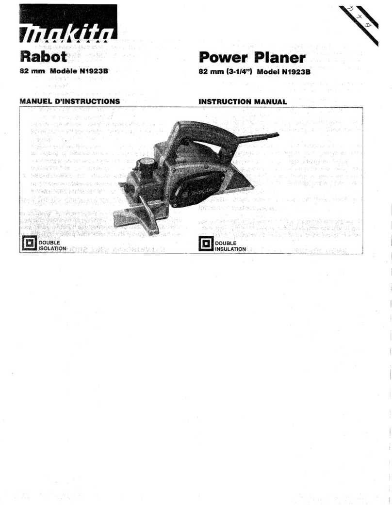
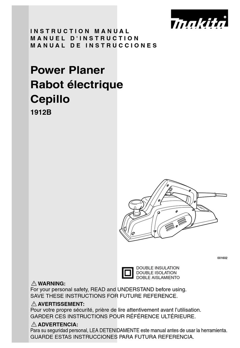
Makita KP0800X User manual

GB Planer Instruction manual
ZHCN
电刨 使用说明书
ID Mesin Serut Petunjuk penggunaan
Máy Bào Cầm Tay Hoạt Động
Bằng Động CơĐiện
VI Tài liệu hướng dẫn
TH กบไฟฟาคูมือการใชงาน
KP0800

2
1010336 2010172
3010173 4002564
5002555 6002556
7002565 8002566
1
2
3
4
56
7
8
9
9
10
5
11
12
13
14
5
12
15
16
17
18
19
20
12
21
18
22
23
24
19
17
25
25
26
23
27
11
10
12

3
9010175 10 007802
11 010176 12 010177
13 010178 14 002580
15 1085601 16 010372
29
28
30
31 29
32
33
14 34
15
35

4
17 010333 18 010183
19 003634 20 010184
21 002588 22 002589
23 002590 24 001145
36
37
38
39 40
41
42

5
25 010335 26 010185
27 010186
43
44
29
44
45 44

6
ENGLISH
Explanation of general view
SPECIFICATIONS
• Due to our continuing program of research and development, the specifications herein are subject to change without
notice.
• Specifications may differ from country to country.
• Weight according to EPTA-Procedure 01/2014
END201-7
Symbols
The following show the symbols used for the equipment.
Be sure that you understand their meaning before use.
.... Read instruction manual.
.............. DOUBLE INSULATION
ENE001-1
Intended use
The tool is intended for planing wood.
ENF002-2
Power supply
The tool should be connected only to a power supply of
the same voltage as indicated on the nameplate, and can
only be operated on single-phase AC supply. They are
double-insulated and can, therefore, also be used from
sockets without earth wire.
GEA012-2
General power tool safety
warnings
WARNING: Read all safety warnings, instructions,
illustrations and specifications provided with this
power tool. Failure to follow all instructions listed below
may result in electric shock, fire and/or serious injury.
Save all warnings and
instructions for future reference.
The term “power tool” in the warnings refers to your
mains-operated (corded) power tool or battery-operated
(cordless) power tool.
Work area safety
1. Keep work area clean and well lit. Cluttered or dark
areas invite accidents.
2. Do not operate power tools in explosive
atmospheres, such as in the presence of
flammable liquids, gases or dust. Power tools
create sparks which may ignite the dust or fumes.
1. Pointer
2. Knob
3. Lock button or Lock-off button
4. Switch trigger
5. Planer blade
6. Rear base
7. Foot
8. Socket wrench
9. Bolt
10. Drum
11. Drum cover
12. Adjusting plate
13. Inside edge of gauge plate
14. Blade edge
15. Screw
16. Heel
17. Back side of gauge base
18. Gauge plate
19. Gauge base
20. Pan head screw
21. Planer blade locating lugs
22. Heel of adjusting plate
23. Set plate
24. Inside flank of gauge plate
25. Mini planer blade
26. Groove
27. Hex. flange head bolt
28. Dust bag
29. Nozzle
30. Fastener
31. Elbow
32. Start
33. End
34. Cutting line
35. Edge fence (Accessory)
36. Sharpening holder
37. Wing nut
38. Blade (A)
39. Blade (B)
40. Side (D)
41. Side (C)
42. Limit mark
43. Chip cover
44. Screwdriver
45. Brush holder cap
Model KP0800
Planing width 82 mm
Planing depth 2.5 mm
Shiplapping depth 9 mm
No load speed (min-1)17,000
Overall length 285 mm
Net weight 2.7 kg
Safety class /II

7
3. Keep children and bystanders away while
operating a power tool. Distractions can cause you
to lose control.
Electrical Safety
1. Power tool plugs must match the outlet. Never
modify the plug in any way. Do not use any
adapter plugs with earthed (grounded) power
tools. Unmodified plugs and matching outlets will
reduce risk of electric shock.
2. Avoid body contact with earthed or grounded
surfaces, such as pipes, radiators, ranges and
refrigerators. There is an increased risk of electric
shock if your body is earthed or grounded.
3. Do not expose power tools to rain or wet
conditions. Water entering a power tool will increase
the risk of electric shock.
4. Do not abuse the cord. Never use the cord for
carrying, pulling or unplugging the power tool.
Keep cord away from heat, oil, sharp edges or
moving parts. Damaged or entangled cords increase
the risk of electric shock.
5. When operating a power tool outdoors, use an
extension cord suitable for outdoor use. Use of a
cord suitable for outdoor use reduces the risk of
electric shock.
6. If operating a power tool in a damp location is
unavoidable, use a residual current device (RCD)
protected supply. Use of an RCD reduces the risk of
electric shock.
7. Use of power supply via an RCD with a rated
residual current of 30 mA or less is always
recommended.
8. Power tools can produce electromagnetic fields
(EMF) that are not harmful to the user. However,
users of pacemakers and other similar medical
devices should contact the maker of their device and/
or doctor for advice before operating this power tool.
9. Do not touch the power plug with wet hands.
10. If the cord is damaged, have it replaced by the
manufacturer or his agent in order to avoid a
safety hazard.
Personal Safety
1. Stay alert, watch what you are doing and use
common sense when operating a power tool. Do
not use a power tool while you are tired or under
the influence of drugs, alcohol or medication. A
moment of inattention while operating power tools
may result in serious personal injury.
2. Use personal protective equipment. Always wear
eye protection. Protective equipment such as a dust
mask, non-skid safety shoes, hard hat or hearing
protection used for appropriate conditions will reduce
personal injuries.
3. Prevent unintentional starting. Ensure the switch
is in the off-position before connecting to power
source and/or battery pack, picking up or carrying
the tool. Carrying power tools with your finger on the
switch or energising power tools that have the switch
on invites accidents.
4. Remove any adjusting key or wrench before
turning the power tool on. A wrench or a key left
attached to a rotating part of the power tool may result
in personal injury.
5. Do not overreach. Keep proper footing and
balance at all times. This enables better control of
the power tool in unexpected situations.
6. Dress properly. Do not wear loose clothing or
jewellery. Keep your hair and clothing away from
moving parts. Loose clothes, jewellery or long hair
can be caught in moving parts.
7. If devices are provided for the connection of dust
extraction and collection facilities, ensure these
are connected and properly used. Use of dust
collection can reduce dust-related hazards.
8. Do not let familiarity gained from frequent use of
tools allow you to become complacent and ignore
tool safety principles. A careless action can cause
severe injury within a fraction of a second.
9. Always wear protective goggles to protect your
eyes from injury when using power tools. The
goggles must comply with ANSI Z87.1 in the USA,
EN 166 in Europe, or AS/NZS 1336 in Australia/
New Zealand. In Australia/New Zealand, it is
legally required to wear a face shield to protect
your face, too.
It is an employer's responsibility to enforce the
use of appropriate safety protective equipments
by the tool operators and by other persons in the
immediate working area.
Power tool use and care
1. Do not force the power tool. Use the correct power
tool for your application. The correct power tool will
do the job better and safer at the rate for which it was
designed.
2. Do not use the power tool if the switch does not
turn it on and off. Any power tool that cannot be
controlled with the switch is dangerous and must be
repaired.
3. Disconnect the plug from the power source and/or
remove the battery pack, if detachable, from the
power tool before making any adjustments,
changing accessories, or storing power tools.
Such preventive safety measures reduce the risk of
starting the power tool accidentally.
4. Store idle power tools out of the reach of children
and do not allow persons unfamiliar with the
power tool or these instructions to operate the
power tool. Power tools are dangerous in the hands
of untrained users.

8
5. Maintain power tools and accessories. Check for
misalignment or binding of moving parts,
breakage of parts and any other condition that
may affect the power tool’s operation. If damaged,
have the power tool repaired before use. Many
accidents are caused by poorly maintained power
tools.
6. Keep cutting tools sharp and clean. Properly
maintained cutting tools with sharp cutting edges are
less likely to bind and are easier to control.
7. Use the power tool, accessories and tool bits etc.
in accordance with these instructions, taking into
account the working conditions and the work to
be performed. Use of the power tool for operations
different from those intended could result in a
hazardous situation.
8. Keep handles and grasping surfaces dry, clean
and free from oil and grease. Slippery handles and
grasping surfaces do not allow for safe handling and
control of the tool in unexpected situations.
9. When using the tool, do not wear cloth work
gloves which may be entangled. The entanglement
of cloth work gloves in the moving parts may result in
personal injury.
Service
1. Have your power tool serviced by a qualified
repair person using only identical replacement
parts. This will ensure that the safety of the power tool
is maintained.
2. Follow instruction for lubricating and changing
accessories.
GEB167-1
PLANER SAFETY WARNINGS
1. Wait for the cutter to stop before setting the tool
down. An exposed rotating cutter may engage the
surface leading to possible loss of control and serious
injury.
2. Hold the power tool by insulated gripping
surfaces, because the cutter may contact its own
cord. Cutting a “live” wire may make exposed metal
parts of the power tool “live” and could give the
operator an electric shock.
3. Use clamps or another practical way to secure and
support the workpiece to a stable platform. Holding
the workpiece by your hand or against the body leaves
it unstable and may lead to loss of control.
4. Rags, cloth, cord, string and the like should never
be left around the work area.
5. Avoid cutting nails. Inspect for and remove all
nails from the workpiece before operation.
6. Use only sharp blades. Handle the blades very
carefully.
7. Be sure the blade installation bolts are securely
tightened before operation.
8. Hold the tool firmly with both hands.
9. Keep hands away from rotating parts.
10. Before using the tool on an actual workpiece, let it
run for a while. Watch for vibration or wobbling
that could indicate poor installation or a poorly
balanced blade.
11. Make sure the blade is not contacting the
workpiece before the switch is turned on.
12. Wait until the blade attains full speed before
cutting.
13. Always switch off and wait for the blades to come
to a complete stop before any adjusting.
14. Never stick your finger into the chip chute. Chute
may jam when cutting damp wood. Clean out
chips with a stick.
15. Do not leave the tool running. Operate the tool
only when hand-held.
16. Always change both blades or covers on the
drum, otherwise the resulting imbalance will
cause vibration and shorten tool life.
17. Use only Makita blades specified in this manual.
18. Always use the correct dust mask/respirator for
the material and application you are working with.
SAVE THESE INSTRUCTIONS.
WARNING:
DO NOT let comfort or familiarity with product (gained
from repeated use) replace strict adherence to safety
rules for the subject product.
MISUSE or failure to follow the safety rules stated in
this instruction manual may cause serious personal
injury.
FUNCTIONAL DESCRIPTION
CAUTION:
• Always be sure that the tool is switched off and
unplugged before adjusting or checking function on the
tool.
Adjusting depth of cut (Fig. 1)
Depth of cut may be adjusted by simply turning the knob
on the front of the tool so that the pointer points the
desired depth of cut.
Switch action (Fig. 2)
CAUTION:
• Before plugging in the tool, always check to see that
the switch trigger actuates properly and returns to the
"OFF" position when released.
For tool with lock button
CAUTION:
• Switch can be locked in "ON" position for ease of
operator comfort during extended use. Apply caution
when locking tool in "ON" position and maintain firm
grasp on tool.
To start the tool, simply pull the switch trigger. Release the
switch trigger to stop.
For continuous operation, pull the switch trigger and then
push in the lock button.
To stop the tool from the locked position, pull the switch
trigger fully, then release it.
For tool with lock-off button
To prevent the switch trigger from being accidentally
pulled, a lock-off button is provided.
To start the tool, depress the lock-off button and pull the
switch trigger. Release the switch trigger to stop.

9
Foot (Fig. 3)
After a cutting operation, raise the back side of the tool
and a foot comes under the level of the rear base. This
prevents the tool blades to be damaged.
ASSEMBLY
CAUTION:
• Always be sure that the tool is switched off and
unplugged before carrying out any work on the tool.
Removing or installing planer blades
CAUTION:
• Tighten the blade installation bolts carefully when
attaching the blades to the tool. A loose installation bolt
can be dangerous. Always check to see they are
tightened securely.
• Handle the blades very carefully. Use gloves or rags to
protect your fingers or hands when removing or
installing the blades.
• Use only the Makita wrench provided to remove or
install the blades. Failure to do so may result in
overtightening or insufficient tightening of the
installation bolts. This could cause an injury.
For tool with conventional planer blades (Fig. 4, Fig. 5
& Fig. 6)
To remove the blades on the drum, unscrew the
installation bolts with the socket wrench. The drum cover
comes off together with the blades.
To install the blades, first clean out all chips or foreign
matter adhering to the drum or blades. Use blades of the
same dimensions and weight, or drum oscillation/vibration
will result, causing poor planing action and, eventually,
tool breakdown.
Place the blade on the gauge base so that the blade edge
is perfectly flush with the inside edge of the gauge plate.
Place the adjusting plate on the blade, then simply press
in the heel of the adjusting plate flush with the back side of
the gauge base and tighten two screws on the adjusting
plate. Now slip the heel of the adjusting plate into the
drum groove, then fit the drum cover on it. Tighten all the
installation bolts evenly and alternately with the socket
wrench.
Repeat the above procedures for the other blade.
For tool with mini planer blades (Fig. 4, Fig. 7 & Fig. 8)
1. Remove the existing blade, if the tool has been in use,
carefully clean the drum surfaces and the drum cover.
To remove the blades on the drum, unscrew the three
installation bolts with the socket wrench. The drum
cover comes off together with the blades.
2. To install the blades, loosely attach the adjusting plate
to the set plate with the pan head screws and set the
mini planer blade on the gauge base so that the
cutting edge of the blade is perfectly flush with the
inside flank of the gauge plate.
3. Set the adjusting plate/set plate on the gauge base so
that the planer blade locating lugs on the set plate rest
in the mini planer blade groove, then press in the heel
of the adjusting plate flush with the back side of the
gauge base and tighten the pan head screws.
4. It is important that the blade sits flush with the inside
flank of the gauge plate, the planer blade locating lugs
sit in the blade groove and the heel of the adjusting
plate is flush with the back side of the gauge base.
Check this alignment carefully to ensure uniform
cutting.
5. Slip the heel of the adjusting plate into the groove of
the drum.
6. Set the drum cover over the adjusting plate/set plate
and screw in the three hex flange head bolts so that a
gap exists between the drum and the set plate to slide
the mini planer blade into position. The blade will be
positioned by the planer blade locating lugs on the set
plate.
7. The blade's lengthwise adjustment will need to be
manually positioned so that the blade ends are clear
and equidistant from the housing on one side and the
metal bracket on the other.
8. Tighten the three hex flange head bolts (with the
socket wrench provided) and rotate the drum to check
clearances between the blade ends and the tool body.
9. Check the three hex flange head bolts for final
tightness.
10. Repeat procedures 1 - 9 for the other blade.

10
For the correct planer blade setting
Your planing surface will end up rough and uneven, unless the blade is set properly and securely. The blade must be
mounted so that the cutting edge is absolutely level, that is, parallel to the surface of the rear base.
Refer to some examples below for proper and improper settings.
Dust bag (accessory) (Fig. 9)
For tool without nozzle
Remove the chip cover and install the nozzle (optional
accessory). Attach the dust bag onto the nozzle. The
nozzle is tapered. When attaching the dust bag, push it
onto the nozzle firmly as far as it will go to prevent it from
coming off during operation.
For tool with nozzle
Attach the dust bag onto the nozzle. The nozzle is
tapered. When attaching the dust bag, push it onto the
nozzle firmly as far as it will go to prevent it from coming
off during operation.
When the dust bag is about half full, remove the dust bag
from the tool and pull the fastener out. Empty the dust bag
of its contents, tapping it lightly so as to remove particles
adhering to the insides which might hamper further
collection. (Fig. 10)
NOTE:
• If you connect a Makita vacuum cleaner to this tool,
more efficient and cleaner operations can be
performed.
Connecting a vacuum cleaner (Fig. 11)
For tool without nozzle
When you wish to perform clean planing operation,
connect a Makita vacuum cleaner to your tool. Before
connecting the vacuum cleaner, remove the chip cover
from the tool. Then connect a hose of the vacuum cleaner
to the nozzle (optional accessory) as shown in the figures.
For tool with nozzle
When you wish to perform clean planing operation,
connect a Makita vacuum cleaner to your tool. Then
connect a hose of the vacuum cleaner to the nozzle as
shown in the figures.
Elbow (optional accessory) (Fig. 12)
Use of elbow allows change of chip discharge direction to
perform cleaner work.
For tool without nozzle
Remove the chip cover and install the nozzle (optional
accessory). Attach the elbow (optional accessory) on the
nozzle of the tool by just slipping on it. To remove it, just
pull it out.
For tool with nozzle
Attach the elbow (optional accessory) on the nozzle of the
tool by just slipping on it. To remove it, just pull it out.
Nozzle cleaning
Clean the nozzle regularly.
Use a compressed air to clean the clogged nozzle.
(A) Front base (Movable shoe)
(B) Rear base (Stationary shoe)
Correct setting
Nicks in surface
Gouging at start
Gouging at end
Although this side view cannot show it,
the edges of the blades run perfectly
parallel to the rear base surface.
Cause: One or both blades fails to have
edge parallel to rear base line.
Cause: One or both blade edges fails to
protrude enough in relation to
rear base line.
Cause: One or both blade edges
protrudes too far in relation to
rear base line.
EN0004-1
(A) (B)
(B)
(A) (B)
(A)

11
OPERATION
WARNING: To reduce the risk of injury to persons,
do not operate without nozzle or chip cover in place.
Hold the tool firmly with one hand on the knob and the
other hand on the switch handle when performing the tool.
Planing operation (Fig. 13)
First, rest the tool front base flat upon the workpiece
surface without the blades making any contact. Switch on
and wait until the blades attain full speed. Then move the
tool gently forward. Apply pressure on the front of tool at
the start of planing, and at the back at the end of planing.
Planing will be easier if you incline the workpiece in
stationary fashion, so that you can plane somewhat
downhill.
The speed and depth of cut determine the kind of finish.
The power planer keeps cutting at a speed that will not
result in jamming by chips. For rough cutting, the depth of
cut can be increased, while for a good finish you should
reduce the depth of cut and advance the tool more slowly.
Shiplapping (Rabbeting)
To make a stepped cut as shown in the figure, use the
edge fence (guide rule) which is obtained as accessory.
(Fig. 14)
Draw a cutting line on the workpiece. Insert the edge
fence into the hole in the front of the tool. Align the blade
edge with the cutting line. (Fig. 15)
Adjust the edge fence until it comes in contact with the
side of the workpiece, then secure it by tightening the
screw. (Fig. 16)
When planing, move the tool with the edge fence flush
with the side of the workpiece. Otherwise uneven planing
may result. (Fig. 17)
Maximum shiplapping (rabbeting) depth is 9 mm.
You may wish to add to the length of the fence by
attaching an extra piece of wood. Convenient holes are
provided in the fence for this purpose, and also for
attaching an extension guide (optional accessory). (Fig.
18)
Chamfering
To make a chamfering cut as shown in the figure, align the
"V" groove in the front base with the edge of the
workpiece and plane it. (Fig. 19 & Fig. 20)
MAINTENANCE
CAUTION:
• Always be sure that the tool is switched off and
unplugged before attempting to perform inspection or
maintenance.
• Never use gasoline, benzine, thinner, alcohol or the
like. Discoloration, deformation or cracks may result.
Sharpening the planer blades
For conventional blades only
Always keep your blades sharp for the best performance
possible. Use the sharpening holder (optional accessory)
to remove nicks and produce a fine edge. (Fig. 21)
First, loosen the two wing nuts on the holder and insert
the blades (A) and (B), so that they contact the sides (C)
and (D). Then tighten the wing nuts. (Fig. 22)
Immerse the dressing stone in water for 2 or 3 minutes
before sharpening. Hold the holder so that the both blades
contact the dressing stone for simultaneous sharpening at
the same angle. (Fig. 23)
Replacing carbon brushes
Remove and check the carbon brushes regularly. Replace
when they wear down to the limit mark. Keep the carbon
brushes clean and free to slip in the holders. Both carbon
brushes should be replaced at the same time. Use only
identical carbon brushes. (Fig. 24)
Use a screwdriver to remove the chip cover or nozzle.
(Fig. 25 & Fig. 26)
Use a screwdriver to remove the brush holder caps. Take
out the worn carbon brushes, insert the new ones and
secure the brush holder caps. (Fig. 27)
To maintain product SAFETY and RELIABILITY, repairs,
any other maintenance or adjustment should be
performed by Makita Authorized Service Centers, always
using Makita replacement parts.
OPTIONAL ACCESSORIES
CAUTION:
• These accessories or attachments are recommended
for use with your Makita tool specified in this manual.
The use of any other accessories or attachments might
present a risk of injury to persons. Only use accessory
or attachment for its stated purpose.
If you need any assistance for more details regarding
these accessories, ask your local Makita Service Center.
• High-speed steel Planer blade
• Tungsten-carbide Planer blade (For longer blade life)
• Mini planer blade
• Sharpening holder assembly
• Blade gauge
• Set plate set
• Edge fence (Guide rule)
• Extension guide set
• Dressing stone
•Nozzle
• Dust bag assembly
•Elbow
•Socketwrench
NOTE:
• Some items in the list may be included in the tool
package as standard accessories. They may differ from
country to country.

12
中文简体
一般外观说明
规格
•由于持续的研发计划,因此生产者保留变更规格而不另行通知之权利。
•规格可能因销往国家之不同而异。
•重量符合 EPTA-Procedure 01/2014
END201-7
符号
以下显示本设备使用的符号。在使用工具之前
请务必理解其含义。
...阅读使用说明书。
.............双重绝缘
ENE001-1
用途
本工具用于对木材进行刨削加工。
ENF002-2
电源
本工具只可连接电压与铭牌所示电压相同的
电源,且仅可使用单相交流电源。本工具双
重绝缘,因此也可用于不带接地线的插座。
GEA012-2
电动工具一般安全警告
警告:请通读本电动工具附带的所有安全
警告、说明、插图和规格。若不遵循下列说
明,则可能导致触电、起火和/或严重的人
身伤害。
1. 指针
2. 旋钮
3. 锁定按钮或锁止按钮
4. 开关扳机
5. 刨刀片
6. 后刨板
7. 底脚
8. 套筒扳手
9. 螺栓
10. 刀筒
11. 刀筒盖
12. 调整板
13. 量规定位板内缘
14. 刀片边缘
15. 螺丝
16. 后跟
17. 量规基板后缘
18. 量规定位板
19. 量规基板
20. 盘头螺丝
21. 刨刀片定位凸片
22. 调整板后跟
23. 固定板
24. 量规定位板内侧面
25. 小型刨刀片
26. 凹槽
27. 内六角法兰头螺栓
28. 集尘袋
29. 集尘口
30. 紧固装置
31. 弯管
32. 前端
33. 尾端
34. 切割线
35. 边缘导板(附件)
36. 刨刀夹
37. 蝶形螺母
38. 刀片(A)
39. 刀片(B)
40. (D)侧
41. (C)侧
42. 界限磨耗线
43. 碎屑盖板
44. 螺丝刀
45. 碳刷夹盖
型号 KP0800
刨削宽度 82 mm
刨削深度 2.5 mm
切槽深度 9 mm
空载速度(/min)17,000
总长度 285 mm
净重 2.7 kg
安全等级 /II

13
请保管好所有的警告和说明,
以备日后参考。
警告中所说的 “电动工具 ”指用电源(接线
式)或电池(充电式)驱动的电动工具。
工作区域安全事项
1. 保持工作区域清洁,照明情况良好。混乱
或黑暗的工作区域容易招致意外情况发
生。
2. 请勿在易爆环境,如有可燃性液体、气体
或粉尘的环境下操作电动工具。电动工具
产生的火花可能会引燃粉尘或气体。
3. 操作电动工具时请让儿童和旁观者远离作
业区域。操作时分心会使您无法正常控制
工具。
电气安全事项
1. 电动工具的插头必须与插座相匹配。切勿
以任何方式对插头进行改装。请勿将任何
适配器插头用于接地的电动工具。使用未
经改装的插头和相匹配的插座可降低触电
的危险。
2. 请避免与接地的表面如管子、散热器、炉
灶以及冰箱等进行身体接触。如果您的身
体接地,将会增加触电的危险。
3. 请勿将电动工具暴露在雨水或潮湿的环境
中。水进入电动工具将增加触电的危险。
4. 请勿滥用导线。切勿用导线拖拽工具或拔
下电动工具的插头。避免使导线受热、沾
染油脂、触碰尖锐的边缘或移动的部件。
破损或缠绕的导线会增加触电的危险。
5. 在室外操作电动工具时,请使用户外专用
的延长线。使用户外专用的导线可降低触
电的危险。
6. 如果必须要在潮湿的场所操作电动工具,
请使用带剩余电流装置(RCD)保护功能
的电源。使用 RCD 可降低触电的危险。
7. 始终建议通过额定剩余电流为 30 mA 或以
下的 RCD 来使用电源。
8. 电动工具会产生对用户无害的电磁场
(EMF)。但是,起搏器和其他类似医疗
设备的用户应在操作本电动工具前咨询其
设备的制造商和/或向医生寻求建议。
9. 请勿用湿手触摸电源插头。
10.如果导线破损,则由制造商或其代理商更
换以避免安全隐患。
人身安全注意事项
1. 操作电动工具时请保持警惕,注意操作安
全,并运用常识。请勿在疲劳状态下,或
者在麻醉品、酒精或其他药物作用的影响
下操作电动工具。在操作电动工具期间分
心可能会导致严重的人身伤害。
2. 请使用个人劳防用品。请务必佩带安全眼
镜。正确使用防尘面罩、防滑安全鞋、硬
质帽子或耳罩等劳防用品可减少人身伤害
的危险。
3. 防止意外启动。在连接至电源和/或电池
组,拿起或搬运工具之前,请确保开关处
于关闭位置。搬运工具时手指放在开关上
或者在开关打开的情况下给工具通电可能
导致意外事故。
4. 在启动工具之前请取下所有的调节钥匙或
扳手。如果工具的旋转部件上留有扳手或
调节钥匙,则可能会导致人身伤害。
5. 操作时手不要伸得太长。操作时请双脚站
稳,始终保持平衡。这样可在意外情况下
较好地控制工具。
6. 着装适当。不要穿宽松衣服或佩戴饰品。
确保头发和衣服远离运动部件。宽松衣
服、佩饰或长发可能会卷入移动的部件。
7. 如果提供了与除尘和集尘设备连接用的装
置,请确保正确连接和使用该等装置。使
用集尘设备可减少与粉尘有关的意外事
件。
8. 不要因为频繁使用工具而产生的熟悉感而
掉以轻心,忽视工具的安全准则。某个粗
心的动作可能在瞬间导致严重的伤害。
9. 务必佩戴护目镜以保护眼睛免受使用电动
工具时造成的伤害。护目镜必须符合美国
ANSI Z87.1、欧 洲 EN 166 或澳大利亚/
新西兰 AS/NZS 1336 标准。在澳大利亚/
新西兰,法律要求佩戴面罩保护脸部。
雇主有责任监督工具操作者和其他近工作
区域人员佩戴合适的安全防护设备。

14
电动工具的使用和保养
1. 不要强力按压电动工具。根据用途使用正
确的电动工具。使用工具时不可超出规定
的额定值,这样才能更好、更安全地完成
作业。
2. 如果工具的开关无法使工具开启和关闭,
则请勿使用该工具。无法通过开关控制的
电动工具非常危险,必须进行维修。
3. 在进行任何调节、更换附件或贮存电动工
具之前,必须拔掉电源插头和/或卸下电
池组(如可拆卸)。这种防护性安全措施
可降低电动工具意外启动的风险。
4. 将闲置的电动工具存放于儿童无法触及之
处,并且不得让任何不熟悉工具或这些说
明事项的人员操作工具。未经训练的用户
使用电动工具可能产生危险。
5. 维护电动工具及其附件。检查运动部件是
否调整到位或卡住,检查零件破损情况和
影响电动工具运行的其他状况。如有损
坏,应在使用前修理好电动工具。许多事
故是由维护不良的电动工具引发的。
6. 保持切割工具的锋利和清洁。保养良好且
具有锋利切边的切割工具不易粘连,并且
易于控制。
7. 按照这些说明事项,根据作业条件和作业
特点来使用电动工具、附件和起子头。将
电动工具用于特定设计用途以外的其他用
途时可能导致意外情况发生。
8. 保持把手和抓握表面干燥、清洁,无油污
和润滑脂。湿滑的把手和抓握表面将导致
操作人员无法在意外情况下安全处理和控
制工具。
9. 使用本工具时,请勿佩戴可能会缠结的布
质工作手套。布质工作手套卷入移动部件
可能会造成人身伤害。
维修服务
1. 请将您的电动工具交由合格的专业维修人
员处理,仅可使用与原部件相同的更换部
件。这样可确保工具的安全性。
2. 根据说明进行润滑和更换附件。
GEB167-1
电刨安全警告
1. 待刀具完全停止后方可放下工具。因为暴
露在外的旋转刀具可能会接触放置位置的
表面,导致工具失控或严重人身伤害。
2. 因为刀具可能会接触到自身的电线,操作
工具时请握住工具的绝缘抓握表面。切割
到“带电 ”的电线时,电动工具上曝露的
金属部分可能也会 “带电 ”,并使操作者触
电。
3. 请使用螺丝钳或其他可行的方式将工件夹
紧并固定在稳定的平台上。手持工件或将
工件抵在身上,可能会导致工件摆放不
稳,使工具失去控制。
4. 工作场地不可留有破布、衣裳、导线、索
线等等。
5. 注意不要切割到铁钉。操作之前请检查并
清除工件上的所有铁钉。
6. 请仅使用锋利的刀片。装卸刀片时,需十
分小心。
7. 操作前务必检查刀片安装螺栓是否紧固。
8. 需用双手握紧工具。
9. 手应远离旋转的部件。
10.在实际的工件上使用工具之前,请先让工
具空转片刻。请注意,振动或摇摆可能表
示安装不当或锯片不平衡。
11. 打开开关前,请确认刀片未与工件接触。
12.在开始切割操作前请等待刀片转速达到全
速。
13.在进行任何调整前,请务必关闭工具电源
并等待刀片完全停止。
14.绝不能用手指挖掏碎屑斜槽。刨削潮湿木
材时,斜槽内容易堆积木屑。请用木棒将
其清除。
15.运行中的工具不可离手放置。只可在手握
工具的情况下操作工具。
16.时常更换刀筒上的刀片或刀盖,以免因经
久使用而形成不平衡,导致振动或缩短工
具使用寿命。
17.请仅使用本说明书中指定的 Makita(牧
田)刀片。
18.根据您操作的材料及应用,请务必使用正
确的防尘面罩/呼吸器。
请保管好本说明书。
警告:
请勿为图方便或因对产品足够熟悉(由于重
复使用而获得的经验)而不严格遵循相关产
品安全规则。
使用不当或不遵循使用说明书中的安全规则
会导致严重的人身伤害。
功能描述
小心:
•在调节或检查工具功能之前,请务必关闭
工具电源开关并拔下电源插头。
调节切割深度(图 1)
只需旋转工具正面的旋钮,使指针指向所需
切割深度便可调节切割深度。

15
开关操作(图 2)
小心:
•插上工具电源插头之前,请务必确认开关
扳机能够正常工作,松开时能回到 “OFF”
(关闭)位置。
对于带锁定按钮的工具
小心:
•长时间使用时,可将开关锁定在 “ON”(打
开)位置,以方便操作。将工具锁定在 “ON”
(打开)位置时请小心,务必握紧工具。
启动工具时,只要扣动开关扳机即可。松开开
关扳机工具即停止。
连续操作时,扣动开关扳机并按下锁定按钮。
从锁定位置停止工具时,可将开关扳机扣到
底,然后松开。
对于带锁止按钮的工具
为避免使用者不小心扣动开关扳机,本工具采
用锁止按钮。
启动工具时,按下锁止按钮,然后扣动开关扳
机即可。松开开关扳机工具即停止。
底脚(图 3)
完成切割操作后,抬起工具后侧,支起后刨
板上的底脚。这样可防止工具刀片受损。
装配
小心:
•对工具进行任何装配操作前,请务必确认工
具已关闭且已拔下电源插头。
拆下或安装刨刀片
小心:
•安装刀片至工具时,请小心地将刀片安装螺
栓旋紧。安装螺栓出现松动会非常危险。请
务必检查安装螺栓,确保其紧固。
•装卸刀片时,需十分小心。拆卸或安装刀片
时,请使用手套或破布保护您的手指。
•仅可使用 Makita(牧田)扳手拆卸或安装刀
片。否则可能会导致安装螺栓安装过紧或者
过松。这样可能会造成人身伤害。
对于使用传统刨刀片的工具(图 4、图 5及
图6)
拆卸刀筒上的刀片时,请使用套筒扳手旋下安
装螺栓。刀筒盖可与刀片同时拆下。
安装刀片时,首先清除吸附在刀筒或刀片上的
所有碎屑或异物。务必使用相同尺寸和重量的
刀片,否则会造成刀筒振动,从而造成刨削动
作不良,以至损坏工具。
将刀片放在量规基板上,使刀片边缘与量规定
位板的内缘完全齐平。将调整板放在刀片上,
然后只需按下与量规基板后侧齐平的调整板
后跟,并将调整板上的两个螺丝拧紧即可。现
在将调整板的后跟滑进刀筒凹槽中,然后将刀
筒盖盖上。最后使用套筒扳手均匀而交替地旋
紧所有安装螺栓。
安装另一刀片时重复上述步骤。
对于使用小型刨刀片的工具(图 4、图 7及
图8)
1. 拆下现有刀片,如果正在使用工具,请仔
细清洁刀筒表面和刀筒盖。拆卸刀筒上的
刀片时,请使用套筒扳手旋下三个安装螺
栓。刀筒盖可与刀片同时拆下。
2. 安装刀片时,使用盘头螺丝将调整板宽松
连接至固定板,并将小型刨刀片放在量规
基板上,使刀片切割边缘与量规定位板的
内侧面完全齐平。
3. 将调整板/固定板放在量规基板上,使固定
板上的刨刀片定位凸片位于小型刨刀片凹
槽中,然后按下与量规基板后侧齐平的调
整板后跟,并将盘头螺丝拧紧。
4. 务必使刀片与量规定位板的内侧面齐平,
刨刀片定位凸片位于刀片凹槽中,且调整
板的后跟与量规基板的后侧齐平。为达到
整齐划一的切削效果,请务必仔细检查并
确认上述对齐情况。
5. 将调整板的后跟滑进刀筒凹槽中。
6. 将刀筒盖放在调整板/固定板上方,螺丝位
于三个内六角法兰头螺栓内,使刀筒和固
定板之间的间隙能够让小型刨刀片滑动到
位。刀片将通过固定板上的刨刀片定位凸
片定位。
7. 需要手动对刀片进行纵向调整,使得刀片
末端不与其他部件接触,与一侧的外壳和
另一侧的金属支架保持等距。
8. 紧固三枚内六角法兰头螺栓(使用附带的
套筒扳手),然后旋转刀筒,检查并确认
刀片末端未与工具机身接触。
9. 最后检查并确认三枚内六角法兰头螺栓已
完全紧固。
10.对于其他刀片,重复步骤 1到9。

16
刨刀片的正确安装
刀片如未正确且牢固安装,则无法在工件上刨出平滑的刨削面。安装刀片时,刀片的切割边须
处于绝对水平位置,并且与后刨板平行。
下图为正确及错误调整示例。
集尘袋(附件)(图 9)
对于没有集尘口的工具
拆下碎屑盖板并安装集尘口(选购附件)。将
集尘袋连接到集尘口上。集尘口为锥形。然后
连接集尘袋,将其牢固推入集尘口,以防其在
操作期间脱落。
对于有集尘口的工具
将集尘袋连接到集尘口上。集尘口为锥形。然
后连接集尘袋,将其牢固推入集尘口,以防其
在操作期间脱落。
当集尘袋已装满一半左右的空间时,从工具上
取下集尘袋并拉出紧固装置。倒空集尘袋并轻
轻拍打,去除附着在集尘袋内壁的碎屑,以便
再次使用。(图 10)
注:
•如果将 Makita(牧田)集尘器与本工具连
接,则可进行更有效和清洁的操作。
连接集尘器(图 11)
对于没有集尘口的工具
当您想进行清洁刨削操作时,请将 Makita(牧
田)集尘器连接至您的工具。连接集尘器前,
请从工具上拆下碎屑盖板。然后如图所示将集
尘器软管接到集尘口(选购附件)上。
对于有集尘口的工具
当您想进行清洁刨削操作时,请将 Makita(牧
田)集尘器连接至您的工具。然后如图所示将
集尘器软管接到集尘口上。
弯管(选购附件)(图 12)
使用弯管可改变碎屑排出方向,使操作更加
清洁。
对于没有集尘口的工具
拆下碎屑盖板并安装集尘口(选购附件)。
只需通过滑动即可将弯管(选购附件)连接
到工具的集尘口上。将其拆下时,只需将其
拔出。
对于有集尘口的工具
只需通过滑动即可将弯管(选购附件)连接
到工具的集尘口上。将其拆下时,只需将其
拔出。
(A)前刨板(可移动)
(B)后刨板(固定)
正确的安装
表面有刻痕
前端有凹陷
尾端有凹陷
虽然该侧视图无法显示实际情
况,但刀锋应完全与后刨板平
行。
原因:一片或两片刀片的刀锋
不平行于后刨板基线。
原因:一片或两片刀片的刀锋
高于后刨板基线距离不
够。
原因:一片或两片刀片的刀锋
距离后刨板基线过高。
EN0004-1
(A) (B)
(B)
(A) (B)
(A)

17
集尘口清洁
定期清洁集尘口。
使用压缩空气清洁堵塞的集尘口。
操作
警告:为降低人身伤害风险,请勿在集尘
口或碎屑盖板未安装到位时进行操作。
操作本工具时请用一只手牢牢抓住旋钮,另
一只手紧握开关把手。
刨削操作(图 13)
首先,将工具前刨板平靠在工件表面,切勿使
刀片与工件有任何接触。启动工具并等待刀片
达到全速运转后再进行操作。然后将工具轻轻
向前移动。刨削开始时在工具的前端施力,刨
削结束时在工具的后端施力。如果您以固定方
式倾斜工件,将更容易进行刨削,因此您可以
略微向下进行刨削。
刨削速度与刨削深度决定了刨削面的种类。保
持电刨以一定速度进行刨削将避免碎屑堵塞。
进行粗切削时,刨削深度将增加,为获得良好
的磨光效果,您应该减小刨削深度并使工具前
进速度减慢。
切槽
若要刨削出如图所示的阶梯状切口,须使用
作为附件的边缘导板(导尺)。(图 14)
在工件上画一条切割线。将边缘导板插入工
具正面的孔中。将刀片边缘与切割线对齐。
(图 15)
调节边缘导板,直至其与工件侧接触,然后
紧固螺丝以固定导板。(图 16)
刨削时,在边缘导板与工件一侧平齐的情况
下移动工具。否则会导致刨削表面不平。
(图 17)
最大切槽深度为 9 mm。
您可能希望通过安装附加木条的方式延长导
板长度。导板上有孔,可方便地插入延伸导
板(选购附件)。(图 18)
斜刨削
进行如图所示的斜刨削时,将前刨板的 “V” 形
槽与工件边缘对齐,然后进行刨削。(图 19
及图 20)
保养
小心:
•检查或保养工具之前,请务必关闭工具电
源开关并拔下插头。
•切勿使用汽油、苯、稀释剂、酒精或类似
物品清洁工具。否则可能会导致工具变
色、变形或出现裂缝。
研磨刨刀片
仅限传统刀片
请保持刀片锐利,以便达到最佳的刨削效果。
使用刨刀夹(选购附件)磨除刀锋上的缺口,
提高刀刃的锋利度。(图 21)
首先,松开刨刀夹上的两个蝶形螺母,并插入
刀片(A)及刀片(B),使两刀片背缘分别接
触到(C)及( D)侧。然后旋紧蝶形螺母。
(图 22)
研磨前,将磨刀石浸水 2或3分钟。将固定在
刨刀夹上的两个刀片刀口斜面靠紧磨刀石进
行研磨,可使两刀片都具有同一刀口斜面。
(图 23)
更换碳刷
定期拆下碳刷进行检查。在碳刷磨损到界限磨
耗线时进行更换。请保持碳刷清洁并使其在碳
刷夹内能自由滑动。两个碳刷应同时替换。请
仅使用相同的碳刷。(图 24)
用螺丝刀取下碎屑盖板或集尘口。(图 25 及
图26)
使用螺丝刀拆下碳刷夹盖。取出已磨损的碳
刷,插入新的碳刷,然后紧固碳刷夹盖。
(图 27)
为了保证产品的安全性与可靠性,任何维修、
保养或调节工作均须由 Makita(牧田)授权的
维修服务中心完成,同时确保始终使用
Makita(牧田)的替换部件。

18
选购附件
小心:
•这些附件或装置专用于本说明书所列的
Makita(牧田)电动工具。使用其他附件
或装置可能导致人身伤害。仅可将附件或
装置用于规定目的。
如您需要了解更多关于这些选购附件的信息,
请咨询当地的 Makita(牧田)维修服务中心。
•高速钢刨刀片
•碳化钨刨刀片(为延长刀片寿命)
•小型刨刀片
•刨刀夹组件
•刀口规
•固定板套件
•边缘导板(导尺)
•延伸导板套件
•磨石
•集尘口
•集尘袋组件
•弯管
•套筒扳手
注:
•本列表中的一些部件可能作为标准配件包
含于工具包装内。它们可能因销往国家之
不同而异。

19
BAHASA INDONESIA
Penjelasan tampilan keseluruhan
SPESIFIKASI
• Karena kesinambungan program penelitian dan pengembangan kami, spesifikasi yang disebutkan di sini dapat
berubah tanpa pemberitahuan.
• Spesifikasi dapat berbeda dari satu negara ke negara lainnya.
• Berat menurut Prosedur EPTA 01/2014
END201-7
Simbol
Berikut ini adalah simbol-simbol yang digunakan pada
peralatan ini.
Pastikan Anda mengerti makna masing-masing simbol
sebelum menggunakan alat.
..... Baca petunjuk penggunaan.
.............. ISOLASI GANDA
ENE001-1
Penggunaan
Mesin ini digunakan untuk menyerut kayu.
ENF002-2
Pasokan daya
Mesin harus terhubung dengan pasokan daya listrik yang
bervoltase sama dengan yang tertera pada pelat nama,
dan hanya dapat dijalankan dengan listrik AC fase
tunggal. Mesin diisolasi ganda dan oleh sebab itu dapat
dihubungkan dengan soket tanpa arde.
GEA012-2
Peringatan keselamatan umum
mesin listrik
PERINGATAN: Bacalah semua peringatan
keselamatan, petunjuk, ilustrasi dan spesifikasi yang
disertakan bersama mesin listrik ini. Kelalaian untuk
mematuhi semua petunjuk yang tercantum di bawah ini
dapat menyebabkan sengatan listrik, kebakaran dan/atau
cedera serius.
Simpanlah semua peringatan dan
petunjuk untuk acuan di masa
depan.
Istilah “mesin listrik” dalam semua peringatan mengacu
pada mesin listrik yang dijalankan dengan sumber listrik
jala-jala (berkabel) atau baterai (tanpa kabel).
Keselamatan tempat kerja
1. Jaga tempat kerja selalu bersih dan
berpenerangan cukup. Tempat kerja yang
berantakan dan gelap mengundang kecelakaan.
1. Penunjuk
2. Tombol
3. Tombol kunci atau Tombol buka
kunci
4. Picu saklar
5. Mata pisau serut
6. Dudukan belakang
7. Bagian kaki
8. Kunci sok
9. Baut
10. Teromol
11. Tutup teromol
12. Pelat penyetel
13. Tepi dalam pelat pengukur
14. Tepi mata pisau
15. Sekrup
16. Tumit
17. Sisi belakang dudukan pengukur
18. Pelat pengukur
19. Dudukan pengukur
20. Baut kepala bulat
21. Tonjolan penepat mata pisau
serut
22. Tumit pelat penyetel
23. Pelat pengatur
24. Sisi sayap dalam pelat pengukur
25. Mata pisau serut mini
26. Alur
27. Baut kepala flensa segi-enam
28. Kantong debu
29. Nosel
30. Pengencang
31. Siku
32. Awal
33. Akhir
34. Garis pemotongan
35. Pembatas tepi (Aksesori)
36. Pemegang mata pisau
37. Mur kupu-kupu
38. Mata pisau (A)
39. Mata pisau (B)
40. Sisi (D)
41. Sisi (C)
42. Tanda batas
43. Tutup serpihan kayu
44. Obeng
45. Tutup tempat sikat
Model KP0800
Lebar penyerutan 82 mm
Kedalaman penyerutan 2,5 mm
Kedalaman lidah/celah papan rebat 9 mm
Kecepatan tanpa beban (min-1)17.000
Panjang keseluruhan 285 mm
Berat bersih 2,7 kg
Kelas keamanan /II

20
2. Jangan gunakan mesin listrik dalam lingkungan
yang mudah meledak, misalnya jika ada cairan,
gas, atau debu yang mudah menyala. Mesin listrik
menimbulkan bunga api yang dapat menyalakan debu
atau uap tersebut.
3. Jauhkan anak-anak dan orang lain saat
menggunakan mesin listrik. Bila perhatian terpecah,
anda dapat kehilangan kendali.
Keamanan Kelistrikan
1. Steker mesin listrik harus cocok dengan
stopkontak. Jangan sekali-kali mengubah steker
dengan cara apa pun. Jangan menggunakan
steker adaptor dengan mesin listrik terbumi
(dibumikan). Steker yang tidak diubah dan
stopkontak yang cocok akan mengurangi risiko
sengatan listrik.
2. Hindari sentuhan tubuh dengan permukaan
terbumi atau yang dibumikan seperti pipa,
radiator, kompor, dan kulkas. Risiko sengatan listrik
bertambah jika tubuh Anda terbumikan atau
dibumikan.
3. Jangan membiarkan mesin listrik kehujanan atau
kebasahan. Air yang masuk ke dalam mesin listrik
akan meningkatkan risiko sengatan listrik.
4. Jangan menyalahgunakan kabel. Jangan sekali-
kali menggunakan kabel untuk membawa,
menarik, atau mencabut mesin listrik dari
stopkontak. Jauhkan kabel dari panas, minyak,
tepian tajam, atau bagian yang bergerak. Kabel
yang rusak atau kusut memperbesar risiko sengatan
listrik.
5. Bila menggunakan mesin listrik di luar ruangan,
gunakan kabel ekstensi yang sesuai untuk
penggunaan di luar ruangan. Penggunaan kabel
yang sesuai untuk penggunaan luar ruangan
mengurangi risiko sengatan listrik.
6. Jika mengoperasikan mesin listrik di lokasi
lembap tidak terhindarkan, gunakan pasokan daya
yang dilindungi peranti imbasan arus (residual
current device - RCD). Penggunaan RCD
mengurangi risiko sengatan listrik.
7. Penggunaan pasokan daya melalui RCD dengan
kapasitas arus sisa 30 mA atau kurang selalu
dianjurkan.
8. Mesin listrik dapat menghasilkan medan magnet
(EMF) yang tidak berbahaya bagi pengguna.
Namun, pengguna alat pacu jantung atau peralatan
medis sejenisnya harus berkonsultasi dengan
produsen peralatan tersebut dan/atau dokter mereka
sebelum mengoperasikan mesin listrik ini.
9. Jangan menyentuh colokan daya dengan tangan
basah.
10. Jika kabel rusak, penggantian harus dilakukan
oleh produsen atau agennya untuk menghindari
bahaya keselamatan.
Keselamatan Diri
1. Jaga kewaspadaan, perhatikan pekerjaan Anda
dan gunakan akal sehat bila menggunakan mesin
listrik. Jangan menggunakan mesin listrik saat
Anda lelah atau di bawah pengaruh obat bius,
alkohol, atau obat. Sekejap saja lalai saat
menggunakan mesin listrik dapat menyebabkan
cedera badan serius.
2. Gunakan alat pelindung diri. Selalu gunakan
pelindung mata. Peralatan pelindung seperti masker
debu, sepatu pengaman anti-selip, helm pengaman,
atau pelindung telinga yang digunakan untuk kondisi
yang sesuai akan mengurangi risiko cedera badan.
3. Cegah penyalaan yang tidak disengaja. Pastikan
bahwa sakelar berada dalam posisi mati (off)
sebelum menghubungkan mesin ke sumber daya
dan/atau paket baterai, atau mengangkat atau
membawanya. Membawa mesin listrik dengan jari
Anda pada sakelarnya atau mengalirkan listrik pada
mesin listrik yang sakelarnya hidup (on) akan
mengundang kecelakaan.
4. Lepaskan kunci-kunci penyetel sebelum
menghidupkan mesin listrik. Kunci-kunci yang
masih terpasang pada bagian mesin listrik yang
berputar dapat menyebabkan cedera.
5. Jangan meraih terlalu jauh. Jagalah pijakan dan
keseimbangan sepanjang waktu. Hal ini
memungkinkan kendali yang lebih baik atas mesin
listrik dalam situasi yang tidak diharapkan.
6. Kenakan pakaian yang memadai. Jangan memakai
pakaian yang longgar atau perhiasan. Jaga jarak
antara rambut dan pakaian Anda dengan
komponen mesin yang bergerak. Pakaian yang
longgar, perhiasan, atau rambut yang panjang dapat
tersangkut pada komponen yang bergerak.
7. Jika tersedia fasilitas untuk menghisap dan
mengumpulkan debu, pastikan fasilitas tersebut
terhubung listrik dan digunakan dengan baik.
Penggunaan pembersih debu dapat mengurangi
bahaya yang terkait dengan debu.
8. Jangan sampai Anda lengah dan mengabaikan
prinsip keselamatan mesin ini hanya karena sudah
sering mengoperasikannya dan sudah merasa
terbiasa. Tindakan yang lalai dapat menyebabkan
cedera berat dalam sepersekian detik saja.
This manual suits for next models
1
Table of contents
Languages:
Other Makita Planer manuals

Makita
Makita KP0800 User manual

Makita
Makita PC5001C Manual

Makita
Makita KP0800 User manual

Makita
Makita KP0800 User manual

Makita
Makita DKP180ZJ User manual

Makita
Makita HG 1100 User manual

Makita
Makita M1100 User manual

Makita
Makita PC5000C User manual

Makita
Makita 1806B User manual

Makita
Makita 1902 User manual

Makita
Makita KP0800/2 User manual

Makita
Makita PC5000C User manual

Makita
Makita PC1100 User manual

Makita
Makita 2012NB User manual

Makita
Makita PC5000C User manual

Makita
Makita N1900B User manual

Makita
Makita HG 1100 User manual

Makita
Makita DKP180 User manual

Makita
Makita 1805N User manual

Makita
Makita PC5000C User manual