Model No.
Description
PRODUCT
CONCEPT AND MAIN APPLICATIONS
P 1 /15
Specification
Standard equipment
Note: The standard equipment for the tool shown above may differ from country to country.
4351T, 4351CT, 4351FCT
Jig Saw
Models 4351T, 4351CT and 4351FCT have been developed
as the successor models of 4341T series models.
In addition to the advantages of the predecessor models,
feature new exterior design with ergonomic rubberized handle.
Top handle type models are also available as 4350T series models.
Optional accessories
Jig saw blades No.51, 58, 59, B-8, B-10 to B-19, B-21 to B-27, B-16L, BR-13
Guide rule, Guide rail, Guide rail adaptor, Anti-splintering device
Hose complete 28-5, Dust nozzle
Specification
Net weight: kg (lbs) 2.4 (5.3) 2.5 (5.5)
Model 4351CT 4351FCT
No load speed: strokes per min.
SteelCapacities: mm (") Wood*1
10 (3/8)
Aluminum 20 (25/32)
135 (5-5/16)
800 - 2,800
Length of stroke: mm (") 26 (1)
Shank type B-type
Protection against electric shock
Power supply cord: m (ft) 2.5 (8.2)*2
Double insulation
*1 when cutting with optional blade No.B-16L *2 Australia, New Zealand: 2.0m (6.6ft)
Cut settings 3 Orbital settings + Straight cutting
Yes (Push-in-lock system)
LED Job light
Variable speed control by dial
Soft start
Constant speed control
Toolless blade change
Yes
Yes
Yes
No
4351T
2,800
No
No
No
No Yes
Electronic
control
4351CT/ 4351FCT
120
110
220
230
240
6.9 720
--- 320 70050/60
3.4 720 320 70050/60
3.3 720 320 70050/60
3.2 720 320 70050/60
6.3 320 70050/60
4351T
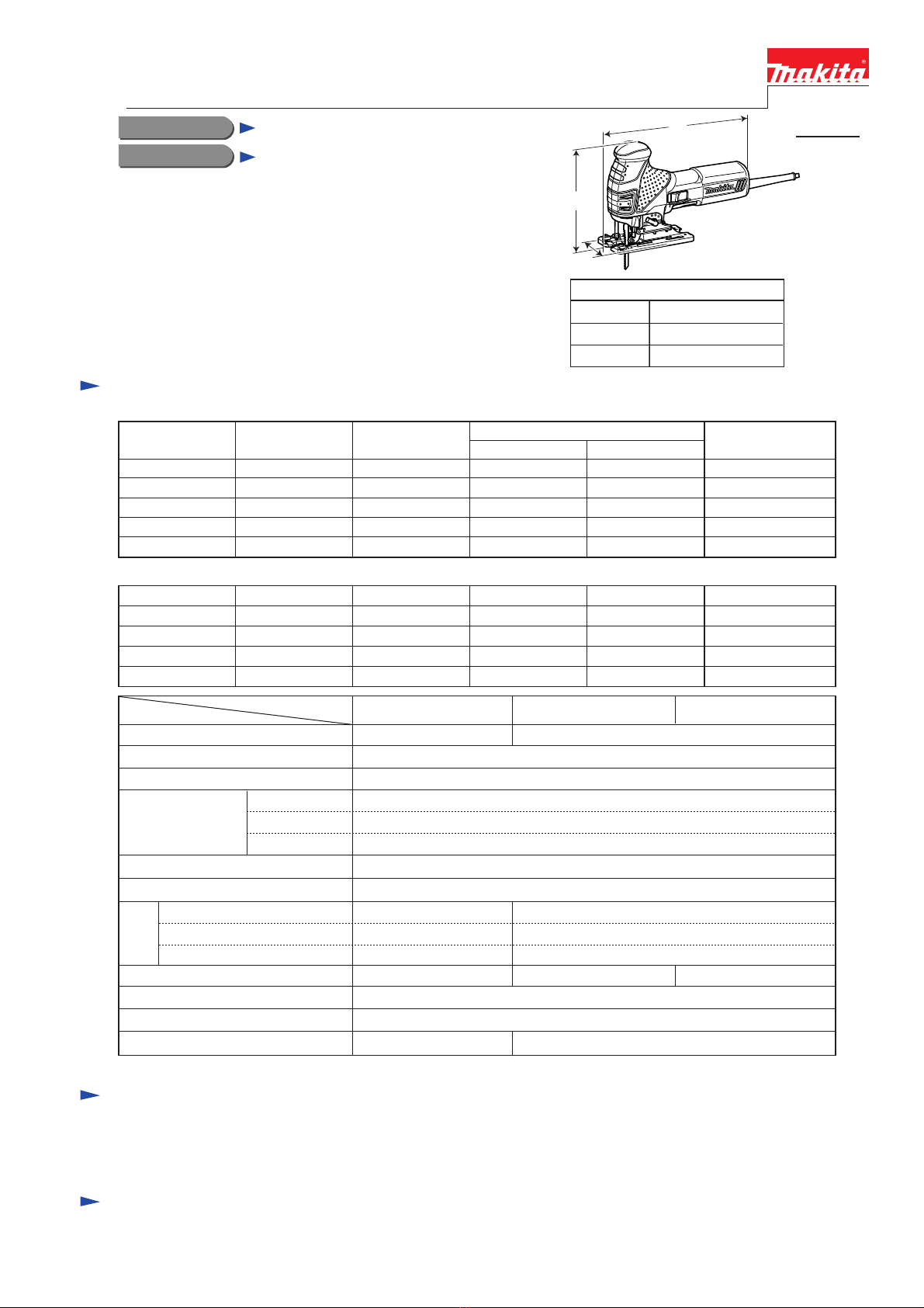
Dimensions: mm (")
Width (W)
Height (H)
Length (L) 271 (10-11/16)
73 (2-7/8)
187 (7-3/8)
L
H
W
TECHNICAL INFORMATION
Continuous Rating (W)
Voltage (V) Cycle (Hz) Input Output Max. Output (W)
220
230
240
Current (A)
2.8 580 300 55050/60
2.7 580 300 55050/60
110
120 5.6 580 300 55050/60
5.1 --- 300 55050/60
2.5 580 300 55050/60
Jig saw blade B-10 ........ 2
Jig saw blade BR-13 ...... 2
Jig saw blade B-22 ........ 2
Cover plate ....................... 1
Anti-splintering device ..... 1
Hex wrench 4 ................... 1
Plastic carrying case ...... 1
Dust nozzle*3................ 1
*3 for European countries only