Makita BTW251RFJ User manual

GB
Cordless Impact Wrench Instruction Manual
F
Boulonneuse sans fil Manuel d’instructions
D
Akku-Schlagschrauber Betriebsanleitung
I
Avvitatrice ad impulso a batteria Istruzioni per l’uso
NL
Snoerloze slagmoersleutel Gebruiksaanwijzing
E
Llave de impacto a batería Manual de instrucciones
P
Chave de impacto a bateria Manual de instruções
DK
Elektronisk akku slagn
ø
gle Brugsanvisning
GR Ασύρματο κροστικ κλειδί Οδηγίες χρήσεως
BTW250
BTW251

2
12
34
56
78
8
10
11
AB
7
4
8
9
1
2
3
5
6
14
12
13
012090
007452
007453
007454
012128
007462
007455
007521

3
9
10 11
12 13
22
21
20
0
160(1632)
140(1428)
120(1224)
100(1020)
80(816)
60(612)
40(408)
20(204)
N m
(kgf cm)
180(1836)
200(2040)
1.0 2.0 3.0
M14
M14
M12
M12
M10
M10
(S)
16 18
17
19
160
140
120
100
80
60
40
20
000.5 1.0 1.5 2.0
M16
M16
M14
M14
M12
M12
(1632)
(1428)
(1224)
(1020)
(816)
(612)
(408)
(204)
N m
(kgf cm)
(S)
16 18
17
15
007461
007535007536
006258 007458

4
14 15
16
27
26
26
23
24 25
007459
006304
007460

5
ENGLISH (Original instructions)
Explanation of general view
1 Red indicator
2 Button
3 Battery cartridge
4 Star marking
5 Switch trigger
6 Lamp
7 Reversing switch lever
8Socket
9Anvil
10 O-ring
11 Pin
12 Hook
13 Screw
14 Groove
15 Standard bolt
16 Fastening torque
17 Fastening time
18 Proper fastening torque
19 High tensile bolt
20 Limit mark
21 Rear cover
22 Screws
23 Spring
24 Arm
25 Recessed part
26 Carbon brush cap
27 Hole
SPECIFICATIONS
• Due to our continuing programme of research and
development, the specifications herein are subject to
change without notice.
• Specifications and battery cartridge may differ from
country to country.
• Weight, with battery cartridge, according to EPTA-
Procedure 01/2003
ENE036-1
Intended use
The tool is intended for fastening bolts and nuts.
GEA010-1
General Power Tool Safety Warnings
WARNING Read all safety warnings and all
instructions. Failure to follow the warnings and
instructions may result in electric shock, fire and/or
serious injury.
Save all warnings and instructions for future reference.
GEB049-2
CORDLESS IMPACT WRENCH SAFETY
WARNINGS
1. Hold power tool by insulated gripping surfaces,
when performing an operation where the fas-
tener may contact hidden wiring. Fasteners con-
tacting a “live” wire may make exposed metal parts
of the power tool “live” and could give the operator
an electric shock.
2. Wear ear protectors.
3. Check the socket carefully for wear, cracks or
damage before installation.
4. Hold the tool firmly.
5. Always be sure you have a firm footing.
Be sure no one is below when using the tool in
high locations.
6. The proper fastening torque may differ depend-
ing upon the kind or size of the bolt. Check the
torque with a torque wrench.
SAVE THESE INSTRUCTIONS.
WARNING:
DO NOT let comfort or familiarity with product
(gained from repeated use) replace strict adherence
to safety rules for the subject product. MISUSE or
failure to follow the safety rules stated in this instruc-
tion manual may cause serious personal injury.
ENC007-7
IMPORTANT SAFETY INSTRUCTIONS
FOR BATTERY CARTRIDGE
1. Before using battery cartridge, read all instruc-
tions and cautionary markings on (1) battery
charger, (2) battery, and (3) product using battery.
2. Do not disassemble battery cartridge.
3. If operating time has become excessively
shorter, stop operating immediately. It may
result in a risk of overheating, possible burns
and even an explosion.
4. If electrolyte gets into your eyes, rinse them out
with clear water and seek medical attention right
away. It may result in loss of your eyesight.
Model BTW250 BTW251
Capacities Standard bolt M10 – M16 M10 – M16
High tensile bolt M10 – M14 M10 – M14
Square drive 12.7 mm 12.7 mm
No load speed (min–1) 0–2,200 0–2,100
Impacts per minute 0 – 3,200 0 – 3,200
Max. fastening torque 230 N•m 230 N•m
Overall length 165 mm 165 mm
Net weight 1.6 kg 1.5 kg
Rated voltage D.C. 14.4 V D.C. 18 V

6
5. Do not short the battery cartridge:
(1) Do not touch the terminals with any conduc-
tive material.
(2) Avoid storing battery cartridge in a container
with other metal objects such as nails, coins,
etc.
(3) Do not expose battery cartridge to water or
rain.
A battery short can cause a large current flow,
overheating, possible burns and even a break-
down.
6. Do not store the tool and battery cartridge in
locations where the temperature may reach or
exceed 50°C (122°F).
7. Do not incinerate the battery cartridge even if it
is severely damaged or is completely worn out.
The battery cartridge can explode in a fire.
8. Be careful not to drop or strike battery.
9. Do not use a damaged battery.
SAVE THESE INSTRUCTIONS.
Tips for maintaining maximum battery life
1. Charge the battery cartridge before completely
discharged.
Always stop tool operation and charge the bat-
tery cartridge when you notice less tool power.
2. Never recharge a fully charged battery cartridge.
Overcharging shortens the battery service life.
3. Charge the battery cartridge with room tempera-
ture at 10°C – 40°C (50°F – 104°F). Let a hot bat-
tery cartridge cool down before charging it.
4. Charge the battery cartridge once in every six
months if you do not use it for a long period of
time.
FUNCTIONAL DESCRIPTION
CAUTION:
• Always be sure that the tool is switched off and the bat-
tery cartridge is removed before adjusting or checking
function on the tool.
Installing or removing battery cartridge (Fig. 1)
• Always switch off the tool before installing or removing
of the battery cartridge.
• To remove the battery cartridge, slide it from the tool
while sliding the button on the front of the cartridge.
• To install the battery cartridge, align the tongue on the
battery cartridge with the groove in the housing and slip
it into place. Always insert it all the way until it locks in
place with a little click. If you can see the red indicator
on the upper side of the button, it is not locked com-
pletely. Install it fully until the red indicator cannot be
seen. If not, it may accidentally fall out of the tool, caus-
ing injury to you or someone around you.
• Do not use force when installing the battery cartridge. If
the cartridge does not slide in easily, it is not being
inserted correctly.
Battery protection system (Lithium-ion battery
with star marking) (Fig. 2)
Lithium-ion batteries with a star marking are equipped
with a protection system. This system automatically cuts
off power to the tool to extend battery life.
The tool will automatically stop during operation if the
tool and/or battery are placed under one of the following
conditions:
• Overloaded:
The tool is operated in a manner that causes it to
draw an abnormally high current.
In this situation, release the trigger switch on the tool
and stop the application that caused the tool to
become overloaded. Then pull the trigger switch
again to restart.
If the tool does not start, the battery is overheated.
In this situation, let the battery cool before pulling the
trigger switch again.
• Low battery voltage:
The remaining battery capacity is too low and the
tool will not operate. In this situation, remove and
recharge the battery.
Switch action (Fig. 3)
CAUTION:
• Before inserting the battery cartridge into the tool,
always check to see that the switch trigger actuates
properly and returns to the “OFF” position when
released.
To start the tool, simply pull the switch trigger. Tool speed
is increased by increasing pressure on the switch trigger.
Release the switch trigger to stop.
Lighting up the front lamp (Fig. 4)
CAUTION:
• Do not look in the light or see the source of light
directly.
Pull the switch trigger to light up the lamp. The lamp
keeps on lighting while the switch trigger is being pulled.
The light automatically goes out 10 – 15 seconds after
the switch trigger is released.
NOTE:
• Use a dry cloth to wipe the dirt off the lens of lamp. Be
careful not to scratch the lens of lamp, or it may lower
the illumination.
Reversing switch action (Fig. 5)
This tool has a reversing switch to change the direction of
rotation. Depress the reversing switch lever from the A
side for clockwise rotation or from the B side for counter-
clockwise rotation.
When the reversing switch lever is in the neutral position,
the switch trigger cannot be pulled.
CAUTION:
• Always check the direction of rotation before operation.
• Use the reversing switch only after the tool comes to a
complete stop. Changing the direction of rotation
before the tool stops may damage the tool.
• When not operating the tool, always set the reversing
switch lever to the neutral position.

7
ASSEMBLY
CAUTION:
• Always be sure that the tool is switched off and the bat-
tery cartridge is removed before carrying out any work
on the tool.
Selecting correct socket
Always use the correct size socket for bolts and nuts. An
incorrect size socket will result in inaccurate and incon-
sistent fastening torque and/or damage to the bolt or nut.
Installing or removing socket (Fig. 6 & 7)
1. For socket without O-ring and pin
To install the socket, push it onto the anvil of the tool
until it locks into place.
To remove the socket, simply pull it off.
2. For socket with O-ring and pin
Move the O-ring out of the groove in the socket and
remove the pin from the socket. Fit the socket onto
the anvil of the tool so that the hole in the socket is
aligned with the hole in the anvil. Insert the pin
through the hole in the socket and anvil. Then return
the O-ring to the original position in the socket
groove to retain the pin. To remove the socket, follow
the installation procedures in reverse.
Hook (Fig. 8)
The hook is convenient for temporarily hanging the tool.
This can be installed on either side of the tool.
To install the hook, insert it into a groove in the tool hous-
ing on either side and then secure it with a screw. To
remove, loosen the screw and then take it out.
OPERATION
CAUTION:
• Always insert the battery cartridge all the way until it
locks in place. If you can see the red part on the upper
side of the button, it is not locked completely. Insert it
fully until the red part cannot be seen. If not, it may
accidentally fall out of the tool, causing injury to you or
someone around you.
Hold the tool firmly and place the socket over the bolt or
nut. Turn the tool on and fasten for the proper fastening
time. (Fig. 9)
The proper fastening torque may differ depending upon
the kind or size of the bolt, the material of the workpiece
to be fastened, etc. The relation between fastening
torque and fastening time is shown in Fig. 10 and
Fig. 11.
NOTE:
• Hold the tool pointed straight at the bolt or nut.
• Excessive fastening torque may damage the bolt/nut or
socket. Before starting your job, always perform a test
operation to determine the proper fastening time for
your bolt or nut.
• If the tool is operated continuously until the battery car-
tridge has discharged, allow the tool to rest for 15 min-
utes before proceeding with a fresh battery cartridge.
The fastening torque is affected by a wide variety of fac-
tors including the following. After fastening, always check
the torque with a torque wrench.
1. When the battery cartridge is discharged almost
completely, voltage will drop and the fastening
torque will be reduced.
2. Socket
• Failure to use the correct size socket will cause a
reduction in the fastening torque.
• A worn socket (wear on the hex end or square
end) will cause a reduction in the fastening torque.
3. Bolt
• Even though the torque coefficient and the class of
bolt are the same, the proper fastening torque will
differ according to the diameter of the bolt.
• Even though the diameters of bolts are the same,
the proper fastening torque will differ according to
the torque coefficient, the class of bolt and the bolt
length.
4. The use of the universal joint or the extension bar
somewhat reduces the fastening force of the impact
wrench. Compensate by fastening for a longer
period of time.
5. The manner of holding the tool or the material of
driving position to be fastened will affect the torque.
6. Operating the tool at low speed will cause a reduc-
tion in the fastening torque.
MAINTENANCE
CAUTION:
• Always be sure that the tool is switched off and the bat-
tery cartridge is removed before attempting to perform
inspection or maintenance.
• Never use gasoline, benzine, thinner, alcohol or the
like. Discoloration, deformation or cracks may result.
Replacing carbon brushes
Replace when they wear down to the limit mark. Keep
the carbon brushes clean and free to slip in the holders.
Both carbon brushes should be replaced at the same
time. Use only identical carbon brushes. (Fig. 12)
Use a screwdriver to remove two screws then remove the
rear cover. (Fig. 13)
Raise the arm part of the spring and then place it in the
recessed part of the housing with a slotted bit screw-
driver of slender shaft or the like. (Fig. 14)
Use pliers to remove the carbon brush caps of the car-
bon brushes. Take out the worn carbon brushes, insert
the new ones and replace the carbon brush caps in
reverse. (Fig. 15 & 16)
Make sure that the carbon brush cap have fit into the
holes in brush holders securely.
Reinstall the rear cover and tighten two screws securely.
To maintain product SAFETY and RELIABILITY, repairs,
any other maintenance or adjustment should be per-
formed by Makita Authorized Service Centers, always
using Makita replacement parts.

8
OPTIONAL ACCESSORIES
CAUTION:
• These accessories or attachments are recommended
for use with your Makita tool specified in this manual.
The use of any other accessories or attachments might
present a risk of injury to persons. Only use accessory
or attachment for its stated purpose.
If you need any assistance for more details regarding
these accessories, ask your local Makita Service Center.
• Sockets
• Extension bar
• Universal joint
• Bit adapter
• Various type of Makita genuine batteries and chargers
NOTE:
• Some items in the list may be included in the tool pack-
age as standard accessories. They may differ from
country to country.
ENG905-1
Noise
The typical A-weighted noise level determined according
to EN60745:
Model BTW250
Sound pressure level (LpA): 90 dB (A)
Sound power level (LWA): 101 dB (A)
Uncertainty (K): 3 dB (A)
Model BTW251
Sound pressure level (LpA): 94 dB (A)
Sound power level (LWA): 105 dB (A)
Uncertainty (K): 3 dB (A)
Wear ear protection
ENG900-1
Vibration
The vibration total value (tri-axial vector sum) determined
according to EN60745:
Model BTW250
Work mode: impact tightening of fasteners of the
maximum capacity of the tool
Vibration emission (ah): 14.5 m/s2
Uncertainty (K): 1.5 m/s2
Model BTW251
Work mode: impact tightening of fasteners of the
maximum capacity of the tool
Vibration emission (ah): 11.0 m/s2
Uncertainty (K): 1.5 m/s2
ENG901-1
• The declared vibration emission value has been mea-
sured in accordance with the standard test method and
may be used for comparing one tool with another.
• The declared vibration emission value may also be
used in a preliminary assessment of exposure.
WARNING:
• The vibration emission during actual use of the power
tool can differ from the declared emission value
depending on the ways in which the tool is used.
• Be sure to identify safety measures to protect the oper-
ator that are based on an estimation of exposure in the
actual conditions of use (taking account of all parts of
the operating cycle such as the times when the tool is
switched off and when it is running idle in addition to
the trigger time).
ENH101-15
For European countries only
EC Declaration of Conformity
We Makita Corporation as the responsible manufac-
turer declare that the following Makita machine(s):
Designation of Machine:
Cordless Impact Wrench
Model No./ Type: BTW250, BTW251
are of series production and
Conforms to the following European Directives:
2006/42/EC
And are manufactured in accordance with the following
standards or standardised documents:
EN60745
The technical documentation is kept by our authorized
representative in Europe who is:
Makita International Europe Ltd.
Michigan Drive, Tongwell,
Milton Keynes, Bucks MK15 8JD, England
30.1.2009
Tomoyasu Kato
Director
Makita Corporation
3-11-8, Sumiyoshi-cho,
Anjo, Aichi, 446-8502, JAPAN

23
NEDERLANDS (Originele instructies)
Verklaring van algemene gegevens
1 Rood aanduiding
2Knop
3 Accu
4 Stermarkering
5 Trekschakelaar
6 Lamp
7 Omkeerschakelaar
8Sok
9Draaistuk
10 O-ring
11 Pen
12 Haak
13 Schroef
14 Groef
15 Standaardbout
16 Aantrekkoppel
17 Aantrektijd
18 Juist aantrekkoppel
19 Bout met hoge trekvastheid
20 Limietmarkering
21 Achterkap
22 Schroeven
23 Veer
24 Arm
25 Verdiepte deel
26 Koolborstelkap
27 Opening
TECHNISCHE GEGEVENS
• In verband met ononderbroken research en ontwikke-
ling behouden wij ons het recht voor bovenstaande
technische gegevens te wijzigen zonder voorafgaande
kennisgeving.
• De technische gegevens de accu kunnen van land tot
land verschillen.
• Gewicht, inclusief accu, volgens de EPTA-procedure
01/2003
ENE036-1
Doeleinden van gebruik
Dit gereedschap is bedoeld voor het vastdraaien van
bouten en moeren.
GEA010-1
Algemene veiligheidswaarschuwingen voor
elektrisch gereedschap
WAARSCHUWING! Lees alle veiligheidswaar-
schuwingen en alle instructies. Het niet volgen van de
waarschuwingen en instructies kan leiden tot elektrische
schokken, brand en/of ernstig letsel.
Bewaar alle waarschuwingen en instructies om in de
toekomst te kunnen raadplegen.
GEB049-2
VEILIGHEIDSWAARSCHUWINGEN SPECIFIEK
VOOR EEN SNOERLOZE SLAGMOERSLEUTEL
1. Houd elektrisch gereedschap vast bij het geïso-
leerde oppervlak van de handgrepen wanneer u
werkt op plaatsen waar het bevestigingsmateri-
aal in aanraking kan komen met verborgen
bedrading. Wanneer bevestigingsmaterialen in aan-
raking komen met onder spanning staande draden,
zullen de niet-geïsoleerde metalen delen van het
gereedschap onder spanning komen te staan zodat
de gebruiker een elektrische schok kan krijgen.
2. Draag oorbeschermers.
3. Controleer de sok nauwkeurig op slijtage,
scheuren of beschadiging alvorens deze op het
gereedschap te monteren.
4. Houd het gereedschap stevig vast.
5. Zorg ervoor dat u altijd stevige steun voor de
voeten hebt.
Controleer of er niemand beneden u aanwezig is
wanneer u het gereedschap op een hoge plaats
gaat gebruiken.
6. Het juiste aantrekkoppel kan verschillen afhan-
kelijk van de soort of grootte van de bout. Con-
troleer het aantrekkoppel met een
momentsleutel.
BEWAAR DEZE VOORSCHRIFTEN.
WAARSCHUWING:
Laat u NIET misleiden door een vals gevoel van com-
fort en bekendheid met het gereedschap (na veelvul-
dig gebruik) en neem alle veiligheidsvoorschriften
van het betreffende gereedschap altijd strikt in acht.
VERKEERD GEBRUIK of het niet naleven van de vei-
ligheidsvoorschriften in deze gebruiksaanwijzing
kan leiden tot ernstige verwondingen.
ENC007-7
BELANGRIJKE
VEILIGHEIDSVOORSCHRIFTEN
VOOR ACCU
1. Lees alle voorschriften en waarschuwingen op
(1) de acculader, (2) de accu, en (3) het product
waarvoor de accu wordt gebruikt, aandachtig
door alvorens de acculader in gebruik te nemen.
Model BTW250 BTW251
Capaciteiten Standaardbout M10 – M16 M10 – M16
Bout met hoge trekvastheid M10 – M14 M10 – M14
Vierkant 12,7 mm 12,7 mm
Toerental onbelast (min–1) 0–2200 0–2100
Aantal slagen per minuut 0–3200 0–3200
Maximaal aantrekkoppel 230 N•m 230 N•m
Totale lengte 165 mm 165 mm
Netto gewicht 1,6 kg 1,5 kg
Nominale spanning D.C. 14,4 V D.C. 18 V

24
2. Neem de accu niet uit elkaar.
3. Als de gebruikstijd van een opgeladen accu aan-
zienlijk korter is geworden, moet u het gebruik
ervan onmiddellijk stopzetten. Voortgezet
gebruik kan oververhitting, brandwonden en
zelfs een ontploffing veroorzaken.
4. Als er elektrolyt in uw ogen is terechtgekomen,
spoel dan uw ogen met schoon water en roep
onmiddellijk de hulp van een dokter in. Elektrolyt
in de ogen kan blindheid veroorzaken.
5. Voorkom kortsluiting van de accu:
(1) Raak de accuklemmen nooit aan met een
geleidend materiaal.
(2) Bewaar de accu niet in een bak waarin
andere metalen voorwerpen zoals spijkers,
munten e.d. worden bewaard.
(3) Stel de accu niet bloot aan water of regen.
Kortsluiting van de accu kan oorzaak zijn van
een grote stroomafgifte, oververhitting, brand-
wonden, en zelfs defecten.
6. Bewaar het gereedschap en de accu niet op
plaatsen waar de temperatuur kan oplopen tot
50°C of hoger.
7. Werp de accu nooit in het vuur, ook niet wanneer
hij zwaar beschadigd of volledig versleten is. De
accu kan namelijk ontploffen in het vuur.
8. Wees voorzichtig dat u de accu niet laat vallen
en hem niet blootstelt aan schokken of stoten.
9. Gebruik nooit een beschadigde accu.
BEWAAR DEZE VOORSCHRIFTEN
Tips voor een maximale levensduur van de accu
1. Laad de accu op voordat hij volledig ontladen is.
Stop het gebruik van het gereedschap en laad de
accu op telkens wanneer u vaststelt dat het ver-
mogen van het gereedschap is afgenomen.
2. Laad een volledig opgeladen accu nooit opnieuw
op. Als u de accu te veel oplaadt, zal hij minder
lang meegaan.
3. Laad de accu op bij een kamertemperatuur tus-
sen 10°C en 40°C. Laat een warme accu afkoelen
alvorens hem op te laden.
4. Laad de accu zeker elk half jaar een keer op, ook
als u deze geruime tijd lang niet gebruikt.
BESCHRIJVING VAN DE FUNCTIES
LET OP:
• Zorg altijd dat het gereedschap is uitgeschakeld en de
accu ervan is verwijderd alvorens de functies op het
gereedschap af te stellen of te controleren.
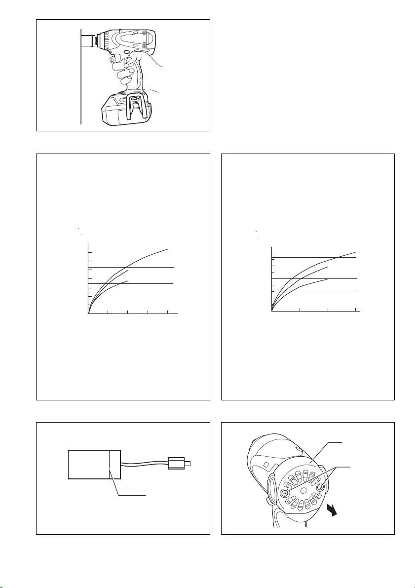
Installeren of verwijderen van de accu (Fig. 1)
• Schakel het gereedschap altijd uit alvorens de accu te
installeren of te verwijderen.
• Om de accu uit het gereedschap te halen, verschuift u
de knop op de voorkant van de accu en trekt u de accu
eraf.
• Om de accu te installeren, doet u de tong op de accu
overeenkomen met de groef in de behuizing en dan
schuift u de accu erin. Schuif de accu zo ver mogelijk
erin totdat deze op zijn plaats vastklikt. Als u de rode
aanduiding boven de knop kunt zien, is ze niet volledig
vergrendeld. Breng de accu dan steviger aan zodat de
rode aanduiding niet meer zichtbaar is. Als u dit niet
doet, kan de accu per ongeluk eruit vallen en uzelf of
andere personen in uw omgeving verwonden.
• Probeer nooit om de accu met geweld te installeren.
Als de accu er niet gemakkelijk ingaat, betekent dit dat
u hem niet op de juiste wijze erin steekt.
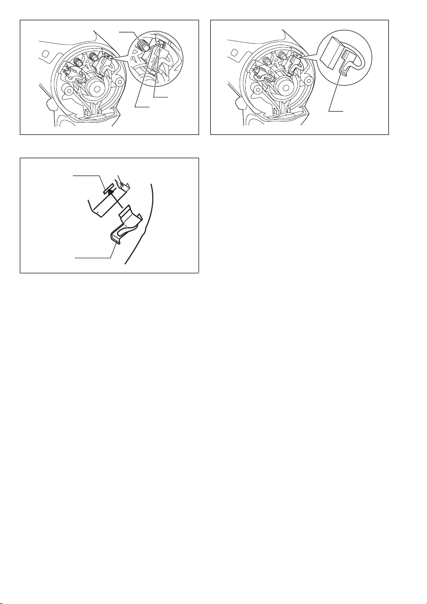
Accubeveiligingssysteem (lithium-ionenaccu met
een stermarkering) (Fig. 2)
Lithium-ionenaccu’s met een stermarkering zijn voorzien
van een beveiligingssysteem. Dat kan automatisch de
stroomtoevoer afsluiten om de levensduur van de accu te
verlengen.
Het gereedschap kan tijdens gebruik automatisch stop-
pen wanneer het gereedschap en/of de accu aan één
van de volgende omstandigheden wordt blootgesteld:
• Overbelasting:
Als het gereedschap wordt gebruikt op een manier
die een abnormaal hoge stroomsterkte vergt.
In dat geval laat u de trekschakelaar van het gereed-
schap los en verhelpt u de oorzaak van de overbe-
lasting. Vervolgens drukt u de trekschakelaar weer
in om het gereedschap te herstarten.
Als het gereedschap niet start, kan de accu overver-
hit zijn. In dat geval laat u de accu even afkoelen
voordat u de trekschakelaar opnieuw indrukt.
• Onvoldoende accuspanning:
Als de resterende accuspanning onvoldoende is, zal
het gereedschap niet starten. In dat geval verwijdert
u de accu en laadt u die opnieuw op.
Werking van de trekschakelaar (Fig. 3)
LET OP:
• Alvorens de accu in het gereedschap te plaatsen, moet
u altijd controleren of de trekschakelaar juist werkt en
bij loslaten naar de “OFF” positie terugkeert.
Om het gereedschap te starten, drukt u gewoon de trek-
schakelaar in. Oefen meer druk uit op de trekschakelaar
om het toerental te vermeerderen. Om het gereedschap
te stoppen, de trekschakelaar loslaten.
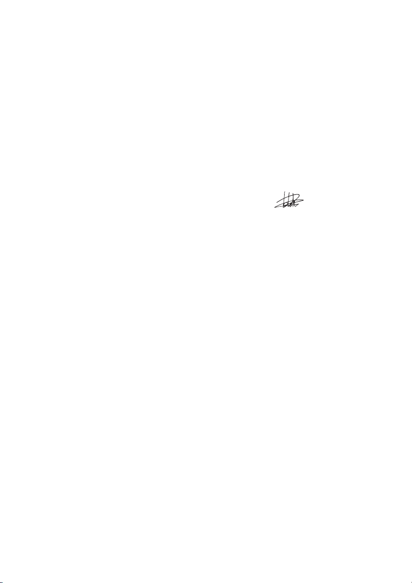
Aanzetten van de voorlamp (Fig. 4)
LET OP:
• Kijk niet direct in het lamplicht of in de lichtbron.
Druk de trekschakelaar in om de lamp aan te zetten. De
lamp blijft branden zolang als de trekschakelaar wordt
ingedrukt.
De lamp gaat 10 tot 15 seconden nadat de aan/uit-scha-
kelaar is losgelaten automatisch uit.
OPMERKING:
• Gebruik een droge doek om vuil op de lamp eraf te
vegen. Pas op dat u geen krassen maakt op de lamp-
lens, omdat de verlichtingssterkte daardoor kan ver-
minderen.
Werking van de omkeerschakelaar (Fig. 5)
Dit gereedschap heeft een omkeerschakelaar voor het
veranderen van de draairichting. Druk de omkeerschake-
laar in vanaf zijde A voor rechtse draairichting, of vanaf
zijde B voor linkse draairichting.
Wanneer deze omkeerschakelaar in de neutrale stand
staat, kan de trekschakelaar niet worden ingedrukt.

25
LET OP:
• Controleer altijd de draairichting alvorens het gereed-
schap te gebruiken.
• Verander de stand van de omkeerschakelaar alleen
nadat het gereedschap volledig tot stilstand is geko-
men. Indien u de draairichting verandert terwijl de boor
nog draait, kan het gereedschap beschadigd raken.
• Zet de omkeerschakelaar altijd in de neutrale stand
wanneer u het gereedschap niet gebruikt.
INEENZETTEN
LET OP:
• Zorg altijd dat het gereedschap is uitgeschakeld en de
accu ervan is verwijderd alvorens enig werk aan het
gereedschap uit te voeren.
Selecteren van de juiste sok
Gebruik altijd een sok van de juiste maat voor het vast-
draaien van bouten en moeren. Het gebruik van een sok
van de onjuiste maat zal een onnauwkeurig of onregel-
matig aantrekkoppel en/of beschadiging van de bout of
moer tot gevolg hebben.
Installeren of verwijderen van de sok (Fig. 6 en 7)
1. Voor een sok zonder O-ring en pen
Installeer de sok door deze op het draaistuk van het
gereedschap te duwen totdat de sok op zijn plaats
vergrendelt.
Om de sok te verwijderen, trekt u deze gewoon eraf.
2. Voor een sok met O-ring en pen
Verwijder de O-ring uit de groef in de sok en verwij-
der de pen uit de sok. Schuif de sok over het draai-
stuk van het gereedschap zodat het gat in de sok op
één lijn komt met het gat in het draaistuk. Steek de
pen door het gat in de sok en in het draaistuk. Breng
de O-ring weer op zijn oorspronkelijke plaats in de
groef aan, zodat de pen op zijn plaats wordt gehou-
den. Om de sok te verwijderen, voert u deze proce-
dure in omgekeerde volgorde uit.
Haak (Fig. 8)
De haak is handig om het gereedschap tijdelijk aan op te
hangen. De haak kan aan beide kanten van het gereed-
schap worden bevestigd.
U bevestigt de haak door deze in een groef in de behui-
zing van het gereedschap te steken en vast te zetten met
een schroef. Om de haak te verwijderen, draait u de
schroef los en haalt u de haak van het gereedschap af.
BEDIENING
LET OP:
• Steek de accu altijd zo ver mogelijk erin totdat hij goed
op zijn plaats vastzit. Als het rode gedeelte op de
bovenkant van de knop nog zichtbaar is, zit de accu
niet volledig erin. Steek hem volledig erin totdat het
rode gedeelte niet meer zichtbaar is. Als de accu niet
goed erin zit, kan hij per ongeluk uit het gereedschap
vallen en kunt u of kunnen anderen in uw omgeving
verwonding oplopen.
Houd het gereedschap stevig vast en plaats de sok over
de bout of moer. Schakel het gereedschap in en draai
vast binnen de juiste aantrektijd. (Fig. 9)
Het juiste aantrekkoppel hangt van het soort of de
grootte van de bout, het materiaal van het te bevestigen
werkstuk, enz. De verhouding tussen het aantrekkoppel
en de aantrektijd is aangegeven in Fig. 10 en Fig. 11.
OPMERKING:
• Houd het gereedschap recht voor de bout of moer.
• Een te hoog aandraaimoment kan de bout/moer of dop
beschadigen. Voordat u het eigenlijke werk begint voert
u daarom altijd eerst een proefbediening uit om het
juiste aandraaimoment voor de bout of moer te bepa-
len.
• Wanneer u het gereedschap doorlopend gebruikt tot-
dat de accu leeg is, moet u het gereedschap 15 minu-
ten laten rusten alvorens met een verse accu verder te
werken.
Het aantrekkoppel wordt beïnvloed door een aantal ver-
schillende factoren, waaronder de volgende. Controleer
na het vastdraaien altijd het aantrekkoppel met een
momentsleutel.
1. Wanneer de accu bijna leeg is, neemt het voltage af
en vermindert het aantrekkoppel.
2. Sok
• Het gebruik van een sok van de onjuiste maat zal
resulteren in een te laag aantrekkoppel.
• Een versleten sok (slijtage op het zeskante of vier-
kante uiteinde) zal resulteren in een te laag aan-
trekkoppel.
3. Bout
• Zelfs wanneer de koppelverhouding en de klasse
van de bout overeenkomen, kan door verschillen
in de diameter van de bouten het juiste aantrek-
koppel per bout toch afwijken.
• Ook al zijn de diameters van twee bouten gelijk,
dan kunnen er nog verschillen in het juiste aan-
trekkoppel van de twee bouten optreden ten
gevolge van verschillen in de koppelverhouding en
de klasse en lengte van de bouten.
4. Het aantrekkoppel is iets lager wanneer een kogel-
gewrichtverbinding of verlengstaaf wordt gebruikt. U
kunt dit verlies aan aantrekkoppel compenseren
door de aantrektijd te verlengen.
5. Het aantrekkoppel wordt beïnvloed door de manier
van vasthouden van het gereedschap of door het
materiaal waarin de bout wordt vastgedraaid.
6. Het aantrekkoppel vermindert wanneer het gereed-
schap bij lage snelheid wordt gebruikt.
ONDERHOUD
LET OP:
• Controleer altijd of het gereedschap is uitgeschakeld
en de accu is losgekoppeld voordat u begint met
inspectie of onderhoud.
• Gebruik nooit benzine, wasbenzine, thinner, alcohol en
dergelijke. Hierdoor het verkleuring, vervormingen en
barsten worden veroorzaakt.
Vervangen van koolborstels
Vervang de koolborstels wanneer ze tot aan de limiet-
markering versleten zijn. Houd de koolborstels schoon
zodat ze goed in de houders glijden. Beide koolborstels
dienen tegelijkertijd te worden vervangen. Gebruik uit-
sluitend identieke koolborstels. (Fig. 12)
Verwijder met behulp van een schroevendraaier de twee
schroeven en vervolgens de achterkap. (Fig. 13)
Til de arm van de veer op en plaats deze vervolgens in
het verdiepte deel van de behuizing met behulp van een
platkopschroevendraaier, een dunne steel, of iets derge-
lijks. (Fig. 14)

26
Verwijder de koolborstelkap van de koolborstels met
behulp van een tang. Haal de versleten koolborstels
eruit, plaats de nieuwe erin, en plaats de koolborstelkap-
pen in omgekeerde volgorde terug. (Fig. 15 en 16)
Zorg ervoor dat iedere koolborstelkap goed in de openin-
gen in de borstelhouder valt.
Plaats de achterkap terug en draai de twee schroeven
stevig aan.
Om de VEILIGHEID en BETROUWBAARHEID van het
product te handhaven, dienen alle reparaties en alle
andere onderhoudswerkzaamheden of afstellingen te
worden uitgevoerd door een erkend Makita Servicecen-
trum, en dat uitsluitend met gebruik van Makita vervan-
gingsonderdelen.
OPTIONELE ACCESSOIRES
LET OP:
• Deze accessoires of hulpstukken worden aanbevolen
voor gebruik met het Makita gereedschap dat in deze
gebruiksaanwijzing is beschreven. Bij gebruik van
andere accessoires of hulpstukken bestaat er gevaar
voor persoonlijke verwonding. Gebruik de accessoires
of hulpstukken uitsluitend voor hun bestemd doel.
Wenst u meer bijzonderheden over deze accessoires,
neem dan contact op met het plaatselijke Makita service-
centrum.
•Sokken
• Verlengstaaf
• Aantrekkoppel
• Bitadapter
• Diverse types originele Makita accu’s en acculaders
OPMERKING:
• Sommige van de onderdelen in deze lijst kunnen bijge-
leverd zijn als standaard-accessoires. Deze accessoi-
res kunnen per land verschillend zijn.
ENG905-1
Geluidsniveau
De typisch, A-gewogen geluidsniveaus vastgesteld vol-
gens EN60745:
Model BTW250
Geluidsdrukniveau (LpA): 90 dB (A)
Geluidsenergie-niveau (LWA): 101 dB (A)
Onnauwkeurigheid (K): 3 dB (A)
Model BTW251
Geluidsdrukniveau (LpA): 94 dB (A)
Geluidsenergie-niveau (LWA): 105 dB (A)
Onnauwkeurigheid (K): 3 dB (A)
Draag oorbeschermers
ENG900-1
Trilling
De totaalwaarde van de trillingen (triaxiale vectorsom)
vastgesteld volgens EN60745:
Model BTW250
Toepassing: bevestigen met behulp van
slagwerking van bevestigingsmiddelen tot de
maximale capaciteit van het gereedschap
Trillingsemissie (ah): 14,5 m/s2
Onnauwkeurigheid (K): 1,5 m/s2
Model BTW251
Toepassing: bevestigen met behulp van
slagwerking van bevestigingsmiddelen tot de
maximale capaciteit van het gereedschap
Trillingsemissie (ah): 11,0 m/s2
Onnauwkeurigheid (K): 1,5 m/s2
ENG901-1
• De opgegeven trillingsemissiewaarde is gemeten vol-
gens de standaardtestmethode en kan worden gebruikt
om dit gereedschap te vergelijken met andere gereed-
schappen.
• De opgegeven trillingsemissiewaarde kan ook worden
gebruikt voor een beoordeling vooraf van de blootstel-
ling.
WAARSCHUWING:
• De trillingsemissie tijdens het gebruik van het elektrisch
gereedschap in de praktijk kan verschillen van de
opgegeven trillingsemissiewaarde afhankelijk van de
manier waarop het gereedschap wordt gebruikt.
• Zorg ervoor dat veiligheidsmaatregelen worden getrof-
fen ter bescherming van de operator die zijn gebaseerd
op een schatting van de blootstelling onder praktijkom-
standigheden (rekening houdend met alle fasen van de
bedrijfscyclus, zoals de tijdsduur gedurende welke het
gereedschap is uitgeschakeld en stationair draait,
naast de ingeschakelde tijdsduur).
ENH101-15
Alleen voor Europese landen
EU-Verklaring van Conformiteit
Wij, Makita Corporation, als de verantwoordelijke
fabrikant, verklaren dat de volgende Makita-
machine(s):
Aanduiding van de machine:
Snoerloze slagmoersleutel
Modelnr./Type: BTW250, BTW251
in serie zijn geproduceerd en
Voldoen aan de volgende Europese richtlijnen:
2006/42/EU
En zijn gefabriceerd in overeenstemming met de vol-
gende normen of genormaliseerde documenten:
EN60745
De technische documentatie wordt bewaard door onze
erkende vertegenwoordiger in Europa, te weten:
Makita International Europe Ltd.
Michigan Drive, Tongwell,
Milton Keynes, Bucks MK15 8JD, Engeland
30.1.2009
Tomoyasu Kato
Directeur
Makita Corporation
3-11-8, Sumiyoshi-cho,
Anjo, Aichi, 446-8502 JAPAN
This manual suits for next models
3
Table of contents
Languages:
Other Makita Power Tools manuals

Makita
Makita DWR180 User manual

Makita
Makita DUX60 User manual

Makita
Makita GWT07 User manual

Makita
Makita Makstar BVR450 User manual

Makita
Makita JS1600 Manual

Makita
Makita DTR180 User manual

Makita
Makita HR2650 User manual

Makita
Makita BJV140 Manual

Makita
Makita HM0810 User manual

Makita
Makita RF1100 User manual

Makita
Makita M4301 User manual

Makita
Makita DTW180 User manual

Makita
Makita HM0870C User manual

Makita
Makita 6934 User manual

Makita
Makita HK0500 User manual

Makita
Makita UX01G User manual

Makita
Makita HM1511 User manual

Makita
Makita DHR263Z User manual

Makita
Makita RP1800FXJ User manual

Makita
Makita HM1202 User manual