Makita DPP200 User manual

INSTRUCTION MANUAL
Cordless Hole Puncher
DPP200
ENGLISH: Original instructions
Read before use.

2ENGLISH
SPECIFICATIONS
Model: DPP200
Max. throat depth 40 mm
Shape of holes Round / Oblong
Max. hole size and thickness For mild steel of 65,000 psi
tensile strength
Diameter : 20 mm
Thickness : 8 mm
For stainless steel of 89,000 psi
tensile strength
Diameter : 20 mm
Thickness : 6 mm
Rated voltage D.C. 18 V
Dimensions (L x W x H)
(with handle)
417 mm x 127 mm x 315 mm
Net weight 10.7 - 10.8 kg
• Duetoourcontinuingprogramofresearchanddevelopment,thespecicationshereinaresubjecttochange
without notice.
• Specicationsmaydifferfromcountrytocountry.
• Weight,withbatterycartridge,accordingtoEPTA-Procedure01/2014
Applicable battery cartridge and charger
Batterycartridge BL1830B / BL1840B / BL1850B / BL1860B
Charger DC18RC/DC18RD/DC18RE/DC18SD/DC18SE/DC18SF/
DC18SH
• Someofthebatterycartridgesandchargerslistedabovemaynotbeavailabledependingonyourregionof
residence.
WARNING: Only use the battery cartridges and chargers listed above.Useofanyotherbatterycartridges
andchargersmaycauseinjuryand/orre.

3ENGLISH
Combination of punch and die
Round punching
Punch Die Workpiece Capacity
Flat bar Max: 80 mm x t8
(Center punching)
Angle Min: 40 mm x 40 mm x t3
Max: 80 mm x 80 mm x t8
Channel Min: 75 mm x 40 mm
Max: 100 mm x 50 mm
(Flange punching)
Unit: mm
Punch Die Tensile Channel Tensile
Mild Steel (65,000 psi) Stainless Steel (89,000 psi)
6SB6 t2 - t4 -t3 - t4
6.5 SB6.5 t2 - t6 -t3 - t4
8SB8 t2 - t6 -t3 - t4
8.5 SB8.5 t2 - t6 -t3 - t4
10 SB10 t2 - t6 t7.5 t3 - t4
11 SB11 t2 - t8 t7.5 t3 - t6
12 SB12 t2 - t8 t7.5 t3 - t6
13 SB13 t2 - t8 t7.5 t3 - t6
14 SB14 t2 - t8 t7.5 t3 - t6
15 SB15 t2 - t8 t7.5 t3 - t6
16 SB16 t2 - t8 t7.5 t3 - t6
18 SB18 t2 - t8 t7.5 t3 - t6
19 SB19 t2 - t8 t7.5 t3 - t6
20 SB20 t2 - t8 t7.5 t3 - t6

4ENGLISH
Oblong punching
Punch Die Workpiece Capacity
Flat bar Max: 80 mm x t8
(Center punching)
Angle Min: 40 mm x 40 mm x t3
Max: 80 mm x 80 mm x t8
Channel Min: 75 mm x 40 mm
Max: 100 mm x 50 mm
(Flange punching)
Unit: mm
Punch Die Tensile Channel Tensile
Mild Steel (65,000 psi) Stainless Steel (89,000 psi)
6.5 x 10 6.5 x 10B t2 - t6 -t3 - t4
6.5 x 13 6.5 x 13B t2 - t6 -t3 - t4
8.5 x 13 8.5 x 13B t2 - t6 -t3 - t4
8.5 x 17 8.5 x 17B t2 - t6 -t3 - t4
9 x 13.5 9 x 13.5B t2 - t6 -t3 - t4
9 x 18 9 x 18B t2 - t6 -t3 - t4
10 x 15 10 x 15B t2 - t8 t7.5 t3 - t6
10 x 20 10 x 20B t2 - t8 t7.5 t3 - t6
11 x 16.5 11 x 16.5B t2 - t8 t7.5 t3 - t6
12 x 18 12 x 18B t2 - t8 t7.5 t3 - t6
13 x 19.5 13 x 19.5B t2 - t8 t7.5 t3 - t6
14 x 21 14 x 21B t2 - t8 t7.5 t3 - t6
Symbols
Thefollowingsshowthesymbolsusedfortheequip-
ment.Besurethatyouunderstandtheirmeaningbefore
use.
Read instruction manual.
Flyingdebrisandloudnoisehazards.Wear
earandeyeprotection.
Hazardous voltage. Disconnect all power
beforeworkingonthisequipment.Failure
toobservethisinstructionmayresultin
deathorpersonalinjury.
Moving blade. Keep hands clear while
machine is operating. Turn power off
before servicing.
Ni-MH
Li-ion
OnlyforEUcountries
Donotdisposeofelectricequipmentor
batterypacktogetherwithhouseholdwaste
material!
InobservanceoftheEuropeanDirectives,
onWasteElectricandElectronic
EquipmentandBatteriesandAccumulators
andWasteBatteriesandAccumulators
and their implementation in accordance
withnationallaws,electricequipmentand
batteriesandbatterypack(s)thathave
reached the end of their life must be col-
lectedseparatelyandreturnedtoanenvi-
ronmentallycompatiblerecyclingfacility.
Intended use
This tool is intended for piercing a hole on steel
material.

5ENGLISH
SAFETY WARNINGS
General power tool safety warnings
WARNING: Read all safety warnings, instruc-
tions, illustrations and specications provided
with this power tool. Failure to follow all instructions
listedbelowmayresultinelectricshock,reand/or
seriousinjury.
Save all warnings and instruc-
tions for future reference.
Theterm"powertool"inthewarningsreferstoyour
mains-operated(corded)powertoolorbattery-operated
(cordless) power tool.
Work area safety
1. Keep work area clean and well lit. Cluttered or
dark areas invite accidents.
2. Do not operate power tools in explosive atmo-
spheres, such as in the presence of ammable
liquids, gases or dust.Powertoolscreatesparks
whichmayignitethedustorfumes.
3. Keep children and bystanders away while
operating a power tool. Distractions can cause
youtolosecontrol.
Electrical safety
1. Power tool plugs must match the outlet. Never
modify the plug in any way. Do not use any
adapter plugs with earthed (grounded) power
tools. Unmodiedplugsandmatchingoutletswill
reduce risk of electric shock.
2. Avoid body contact with earthed or grounded
surfaces, such as pipes, radiators, ranges and
refrigerators. There is an increased risk of elec-
tricshockifyourbodyisearthedorgrounded.
3. Do not expose power tools to rain or wet con-
ditions. Water entering a power tool will increase
the risk of electric shock.
4. Do not abuse the cord. Never use the cord for
carrying, pulling or unplugging the power tool.
Keep cord away from heat, oil, sharp edges
or moving parts. Damaged or entangled cords
increase the risk of electric shock.
5. When operating a power tool outdoors, use an
extension cord suitable for outdoor use. Use of
a cord suitable for outdoor use reduces the risk of
electric shock.
6. If operating a power tool in a damp location
is unavoidable, use a residual current device
(RCD) protected supply. Use of an RCD reduces
the risk of electric shock.
7. Power tools can produce electromagnetic
elds (EMF) that are not harmful to the user.
However, users of pacemakers and other similar
medical devices should contact the maker of their
device and/or doctor for advice before operating
this power tool.
Personal safety
1. Stay alert, watch what you are doing and use
common sense when operating a power tool.
Do not use a power tool while you are tired or
under the inuence of drugs, alcohol or med-
ication.Amomentofinattentionwhileoperating
powertoolsmayresultinseriouspersonalinjury.
2. Use personal protective equipment. Always
wear eye protection.Protectiveequipmentsuch
asadustmask,non-skidsafetyshoes,hardhator
hearing protection used for appropriate conditions
willreducepersonalinjuries.
3. Prevent unintentional starting. Ensure the
switch is in the off-position before connecting
to power source and/or battery pack, picking
up or carrying the tool.Carryingpowertoolswith
yourngerontheswitchorenergisingpowertools
that have the switch on invites accidents.
4. Remove any adjusting key or wrench before
turning the power tool on.Awrenchorakeyleft
attachedtoarotatingpartofthepowertoolmay
resultinpersonalinjury.
5. Do not overreach. Keep proper footing and
balance at all times. This enables better control
of the power tool in unexpected situations.
6. Dress properly. Do not wear loose clothing or
jewellery. Keep your hair and clothing away
from moving parts.Looseclothes,jewelleryor
long hair can be caught in moving parts.
7. If devices are provided for the connection of
dust extraction and collection facilities, ensure
these are connected and properly used. Use of
dust collection can reduce dust-related hazards.
8. Do not let familiarity gained from frequent use
of tools allow you to become complacent and
ignore tool safety principles.Acarelessaction
cancausesevereinjurywithinafractionofa
second.
9. Always wear protective goggles to protect
your eyes from injury when using power tools.
The goggles must comply with ANSI Z87.1 in
the USA, EN 166 in Europe, or AS/NZS 1336
in Australia/New Zealand. In Australia/New
Zealand, it is legally required to wear a face
shield to protect your face, too.
It is an employer's responsibility to enforce
the use of appropriate safety protective equip-
ments by the tool operators and by other per-
sons in the immediate working area.

6ENGLISH
Power tool use and care
1. Do not force the power tool. Use the correct
power tool for your application. The correct
powertoolwilldothejobbetterandsaferatthe
rate for which it was designed.
2. Do not use the power tool if the switch does
not turn it on and off.Anypowertoolthatcannot
be controlled with the switch is dangerous and
must be repaired.
3. Disconnect the plug from the power source
and/or remove the battery pack, if detachable,
from the power tool before making any adjust-
ments, changing accessories, or storing power
tools.Suchpreventivesafetymeasuresreduce
theriskofstartingthepowertoolaccidentally.
4. Store idle power tools out of the reach of chil-
dren and do not allow persons unfamiliar with
the power tool or these instructions to operate
the power tool.Powertoolsaredangerousinthe
hands of untrained users.
5. Maintain power tools and accessories. Check
for misalignment or binding of moving parts,
breakage of parts and any other condition that
may affect the power tool’s operation. If dam-
aged, have the power tool repaired before use.
Manyaccidentsarecausedbypoorlymaintained
power tools.
6. Keep cutting tools sharp and clean.Properly
maintained cutting tools with sharp cutting edges
arelesslikelytobindandareeasiertocontrol.
7. Use the power tool, accessories and tool bits
etc. in accordance with these instructions, tak-
ing into account the working conditions and
the work to be performed. Use of the power tool
for operations different from those intended could
result in a hazardous situation.
8. Keep handles and grasping surfaces dry,
clean and free from oil and grease.Slippery
handles and grasping surfaces do not allow for
safe handling and control of the tool in unexpected
situations.
9. When using the tool, do not wear cloth work
gloves which may be entangled. The entangle-
mentofclothworkglovesinthemovingpartsmay
resultinpersonalinjury.
Battery tool use and care
1. Recharge only with the charger specied by
the manufacturer.Achargerthatissuitablefor
onetypeofbatterypackmaycreateariskofre
whenusedwithanotherbatterypack.
2. Use power tools only with specically desig-
nated battery packs.Useofanyotherbattery
packsmaycreateariskofinjuryandre.
3. When battery pack is not in use, keep it away
from other metal objects, like paper clips,
coins, keys, nails, screws or other small metal
objects, that can make a connection from one
terminal to another.Shortingthebatterytermi-
nalstogethermaycauseburnsorare.
4. Under abusive conditions, liquid may be
ejected from the battery; avoid contact. If con-
tact accidentally occurs, ush with water. If
liquid contacts eyes, additionally seek medical
help.Liquidejectedfromthebatterymaycause
irritation or burns.
5. Do not use a battery pack or tool that is dam-
aged or modied.Damagedormodiedbatteries
mayexhibitunpredictablebehaviourresultingin
re,explosionorriskofinjury.
6. Do not expose a battery pack or tool to re or
excessive temperature.Exposuretoreortem-
peratureabove130°Cmaycauseexplosion.
7. Follow all charging instructions and do not
charge the battery pack or tool outside the
temperature range specied in the instruc-
tions.Chargingimproperlyorattemperatures
outsidethespeciedrangemaydamagethe
batteryandincreasetheriskofre.
Service
1. Have your power tool serviced by a qualied
repair person using only identical replacement
parts.Thiswillensurethatthesafetyofthepower
tool is maintained.
2. Never service damaged battery packs. Service
ofbatterypacksshouldonlybeperformedbythe
manufacturer or authorized service providers.
3. Follow instruction for lubricating and chang-
ing accessories.
Safety instructions for Cordless
Hole Puncher
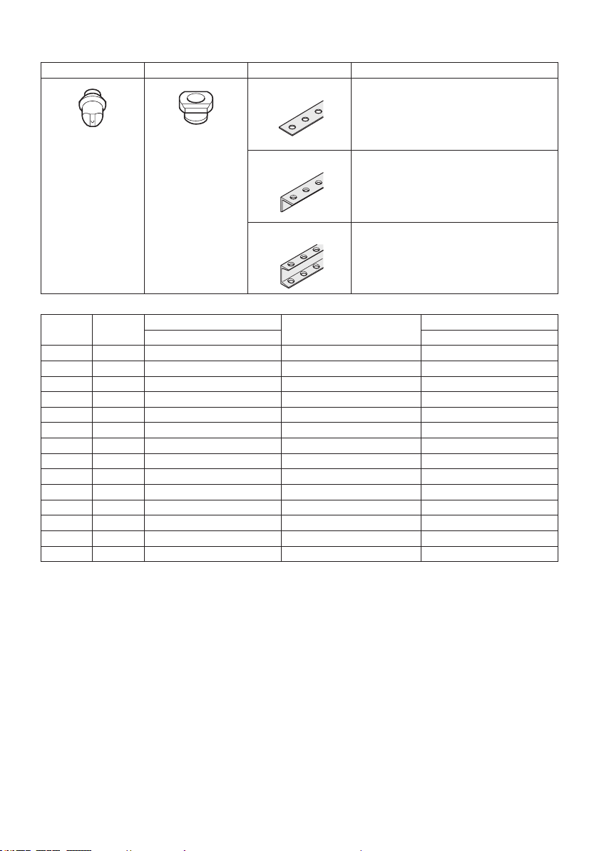
1. Proper selection of the punch and the die is
essential. Select the correct punch and die
according to the hole shape, size of hole,
workpiece thickness and material type.
2.
Ensure that any punch with stepped edge, which pre-
vents free rotation, is installed correctly in the punch
piston before tightening the punch retaining nut.
3.
For punching channel-shaped workpiece and
the workpiece made of stainless steel, use the
die provided exclusively for these materials.
Only select the combination of the punch and
die that is suitable for the workpiece thickness.
4. Ensure the punch and the die are rmly xed
in position with the nut or the bolt. Failure to
dosomaycauseseriousdamagetoyourtool
andseriouspersonalinjury.Regularlycheckand
tighten the punch and die.
5. The tool is electro-hydraulic. When the tem-
perature is cold, it should be run for a few
minutes at idle before starting operations.
6. Keep face, hands and other parts of your body
away from the punching area during operation.
7. Remove the battery cartridge before changing
the punch and the die or when servicing or
making adjustments.
8. The punch and the die that become worn,
deformed, nicked, broken or damaged in any
way may cause a tool breakdown and a seri-
ous accident. Replace them immediately with
new ones supplied from Makita.
9. When punching stainless steel, the punch
and die may wear earlier than punching softer
materials. Ensure that the punch and die are
in good condition, free from wear and are not
deformed, nicked, broken or damaged in any
way. Check with your dealer before punching
any material not listed in the specications.

7ENGLISH
10. Remove and check the carbon brushes reg-
ularly. Replace them after 200 times of use.
Carbon brushes with a length of about 6 mm or
lessmaycausedamagetothemotor.
11. When using the tool continuously, its tempera-
ture can exceed 70 °C which may cause lower
performance. In this case, stop operating for
about 1 hour to allow the tool to cool down
before using it again.
12. Do not cover or clog the motor air vents as this
may cause the motor to overheat, resulting in
smoke, re and explosion.
Important safety instructions for
battery cartridge
1. Before using battery cartridge, read all instruc-
tions and cautionary markings on (1) battery
charger, (2) battery, and (3) product using
battery.
2. Do not disassemble battery cartridge.
3. If operating time has become excessively
shorter, stop operating immediately. It may
result in a risk of overheating, possible burns
and even an explosion.
4. If electrolyte gets into your eyes, rinse them
out with clear water and seek medical atten-
tion right away. It may result in loss of your
eyesight.
5. Do not short the battery cartridge:
(1) Do not touch the terminals with any con-
ductive material.
(2) Avoid storing battery cartridge in a con-
tainer with other metal objects such as
nails, coins, etc.
(3) Do not expose battery cartridge to water
or rain.
A battery short can cause a large current
ow, overheating, possible burns and even a
breakdown.
6. Do not store the tool and battery cartridge in
locations where the temperature may reach or
exceed 50 °C (122 °F).
7. Do not incinerate the battery cartridge even if
it is severely damaged or is completely worn
out. The battery cartridge can explode in a re.
8. Be careful not to drop or strike battery.
9. Do not use a damaged battery.
10.
The contained lithium-ion batteries are subject to
the Dangerous Goods Legislation requirements.
Forcommercialtransportse.g.bythirdparties,
forwardingagents,specialrequirementonpack-
aging and labeling must be observed.
For preparation of the item being shipped, consult-
inganexpertforhazardousmaterialisrequired.
Pleasealsoobservepossiblymoredetailed
national regulations.
Tape or mask off open contacts and pack up the
batteryinsuchamannerthatitcannotmove
around in the packaging.
11. When disposing the battery cartridge, remove
it from the tool and dispose of it in a safe
place. Follow your local regulations relating to
disposal of battery.
12. Use the batteries only with the products
specied by Makita. Installing the batteries to
non-compliantproductsmayresultinare,exces-
siveheat,explosion,orleakofelectrolyte.
13. If the tool is not used for a long period of time,
the battery must be removed from the tool.
SAVE THESE INSTRUCTIONS.
CAUTION: Only use genuine Makita batteries.
Use of non-genuine Makita batteries, or batteries that
havebeenaltered,mayresultinthebatterybursting
causingres,personalinjuryanddamage.Itwill
alsovoidtheMakitawarrantyfortheMakitatooland
charger.
Tips for maintaining maximum
battery life
1. Charge the battery cartridge before completely
discharged. Always stop tool operation and
charge the battery cartridge when you notice
less tool power.
2. Never recharge a fully charged battery car-
tridge. Overcharging shortens the battery
service life.
3. Charge the battery cartridge with room tem-
perature at 10 °C - 40 °C (50 °F - 104 °F). Let
a hot battery cartridge cool down before
charging it.
4. Charge the battery cartridge if you do not use
it for a long period (more than six months).

8ENGLISH
PARTS DESCRIPTION
1
3
4
5
2
67
8
9
10
11
12
14
13
1Motor 2Safetylabel 3Pumpcase 4Punchretainingnut
5Punch 6Die 7Stripper 8C frame
9Slide stopper 10 Return lever 11 Oil port 12 Switch trigger
13 Trigger lock button 14 Batterycartridge - - - -
FUNCTIONAL
DESCRIPTION
CAUTION: Always be sure that the tool is
switched off and the battery cartridge is removed
before adjusting or checking function on the tool.
Installing or removing battery
cartridge
CAUTION: Always switch off the tool before
installing or removing of the battery cartridge.
CAUTION: Hold the tool and the battery car-
tridge rmly when installing or removing battery
cartridge.Failuretoholdthetoolandthebattery
cartridgermlymaycausethemtoslipoffyourhands
andresultindamagetothetoolandbatterycartridge
andapersonalinjury.
1
2
3
►1. Red indicator 2. Button 3.Batterycartridge
Toremovethebatterycartridge,slideitfromthetool
while sliding the button on the front of the cartridge.
Toinstallthebatterycartridge,alignthetongueonthe
batterycartridgewiththegrooveinthehousingandslip
itintoplace.Insertitallthewayuntilitlocksinplace
withalittleclick.Ifyoucanseetheredindicatoronthe
uppersideofthebutton,itisnotlockedcompletely.

9ENGLISH
CAUTION: Always install the battery cartridge
fully until the red indicator cannot be seen. If not,
itmayaccidentallyfalloutofthetool,causinginjuryto
youorsomeonearoundyou.
CAUTION: Do not install the battery cartridge
forcibly.Ifthecartridgedoesnotslideineasily,itis
notbeinginsertedcorrectly.
Battery protection system
Thetoolisequippedwithabatteryprotectionsystem.
Thissystemautomaticallycutsoffpowertothemotorto
extendtoolandbatterylife.Thetoolwillautomatically
stopduringoperationifthetoolorbatteryisplaced
under the following condition.
Overdischarge protection
Whenthebatterycapacityisnotenough,thetoolstops
automatically.Inthiscase,removethebatteryfromthe
toolandchargethebattery.
Indicating the remaining battery
capacity
Only for battery cartridges with the indicator
1
2
►1. Indicator lamps 2. Check button
Pressthecheckbuttononthebatterycartridgetoindi-
catetheremainingbatterycapacity.Theindicatorlamps
light up for a few seconds.
Indicator lamps Remaining
capacity
Lighted Off Blinking
75% to 100%
50% to 75%
25% to 50%
0% to 25%
Charge the
battery.
Thebattery
mayhave
malfunctioned.
NOTE: Depending on the conditions of use and the
ambienttemperature,theindicationmaydifferslightly
fromtheactualcapacity.
Switch action
CAUTION: Before installing the battery car-
tridge into the tool, always check to see that the
switch trigger actuates properly and returns to
the "OFF" position when released.
CAUTION: Always lock the switch trigger
when not in use.
When punching a workpiece, continue to pull the switch
trigger until the punch goes down to the die and returns
to the start position.
To lock the switch trigger, push in the trigger lock button
from B side. To unlock, push in the trigger lock button
fromAside
1
2
►1. Trigger lock button 2. Switch trigger
Rotatable grip
The grip can be rotated though 360 degrees, in either
direction,duringoperation.Thisfeatureisparticularly
useful when working in awkward or narrow areas as it
allows the operator to position the tool in the best posi-
tionforeasyoperation.

10 ENGLISH
ASSEMBLY
CAUTION: Always be sure that the tool is
switched off and the battery cartridge is removed
before carrying out any work on the tool.
Replacing the punch and die
Replacing round punch
1
2
3
4
1
►1. Stripper 2. Nut and set bolt 3.Punchretainingnut
4. Round punch
1. Besurethatthepunchpistonisfullyretractedand
remove the strippers to make access to the parts easier.
2. Thepunchmustberemovedrstandthenthedie.
Unscrew the punch retaining nut to remove the punch
and remove the set bolt and the nut to remove the die.
NOTICE: When replacing the punch and the die,
make sure that the correct size, thickness and
hole shape is selected. Shaped punches and dies
must be properly aligned with each other.
3. PlacethedieintheCframeintheproperorienta-
tion.Securermlywiththesetboltandtightenthenut.
4. Placethepunchinthepunchretainingnut.Insert
the punch with the nut into the punch piston and hand
tighten the nut.
NOTICE: When installing a punch with a stepped
edge (anti rotation), make sure the orientation
is correct and that the stepped edge is correctly
positioned in the punch piston.
5. Makesurethepunchiscorrectlypositionedinthe
punchrodandtightenthepunchretainingnutrmlywith
the nut retaining bar supplied.
1
2
3
4
►1. Nut retaining bar 2.Punchretainingnut
3. Loosen 4. Tighten
6. Restore the strippers.
WARNING: If the punch and die are not
the same size or the punch and the die are not
positioned properly, the punch may strike the
die causing both parts to break. In such a case,
pieces ying off from the broken parts may cause
personal injury.
CAUTION: Check the buttery bolts which
hold the stripper regularly to ensure that they are
tight. Loose bolts may cause the stripper to come
off and damage the tool.
Replacing oblong punch
1
2
3
4
1
4
6
5
►1. Stripper 2. Nut and set bolt 3.Punchretainingnut
4. Oblong punch 5. Stepped edge 6.Punchrod
1. Besurethatthepunchpistonisfullyretractedand
remove the strippers to make access to the parts easier.

11 ENGLISH
2. Thepunchmustberemovedrstandthenthedie.
Unscrew the punch retaining nut to remove the punch
and remove the set bolt and the nut to remove the die.
NOTICE: When replacing the punch and the die,
make sure that the correct size, thickness and
hole shape is selected. Shaped punches and dies
must be properly aligned with each other.
3. Securetheoblongdiermlywiththesetboltand
tighten the nut.
4. Placetheoblongpunchintothepunchretaining
nut.Positionthesteppededgeoftheoblongpunch
properlyinthepunchpistonandhandtightenthepunch
retaining nut.
NOTICE: If the stepped edge of the oblong
punch is not properly inserted into the punch
piston, the punch retaining nut cannot be fas-
tened. Make sure the oblong punch is positioned
correctly in the punch rod.
5. Pushtheoblongpunchagainstthepunchrodand
tightenthepunchretainingnutrmlywiththenutrmly
with the nut retaining bar supplied.
1
2
3
4
►1. Nut retaining bar 2.Punchretainingnut
3. Loosen 4. Tighten
6. Restore the strippers.
WARNING: If the punch and die are not
the same size or the punch and the die are not
positioned properly, the punch may strike the
die causing both parts to break. In such a case,
pieces ying off from the broken parts may cause
personal injury.
CAUTION: Check the buttery bolts which
hold the stripper regularly to ensure that they are
tight. Loose bolts may cause the stripper to come
off and damage the tool.
CAUTION: Make sure the stepped edge of
the oblong punch is positioned correctly in the
punch rod and the punch retaining nut is properly
fastened.
OPERATION
Correct use of the tool
Die selection
It is important that the die to be used is correct for the
thicknessoftheworkpiecetobepunched.Punching
the workpiece of 4 mm to 8 mm thickness using a die
forthinnerworkpiececancausethepunchtojaminthe
workpiece. This is due to the smaller clearance between
the die and punch. In such a case, the workpiece will be
pulledupbytheretractingpunchasshowninthegure.
Specialcareshouldbetakenwhenpunchingatbarof
mild steel, aluminum and copper.
1
►1. Workpiece
Correct use of the stripper
Do not position the workpiece with one end or both
endsunsupportedbythestripper.Iftheworkpieceisnot
properlysupported,itwillmovewhenthepunchreturns.
Itmaycausethepunchtojamanddamagingthetool.
1
2
►1. Stripper 2. Workpiece

12 ENGLISH
Punching a hole
CAUTION:
Before punching, always make sure
that the proper punch and die are installed correctly.
1. Check the position for punching.
1
2
3
1
►1.Punch2. Flat bar 3. Die
2. Loosen the cap screw on the slide stopper and
adjusttheslidestoppertothedesiredposition.After
that, retighten the cap screw.
NOTE:
The slide stopper is set to hold the hole puncher
at a constant distance from the edge of the work piece.
3. Checkthatthereturnleverisfullyclosedinthe
clockwise direction.
1
2
3
4
►1. Spring pin 2. Return lever 3. Open position
4. Closed position
4. Checkthatthepunchpistonisfullyretracted.
5.
Placethepuncherintherequiredpositiononthe
workpieceusingtheslidestopperasaguide.Alignthepoint
of the punch with the center mark of the hole to be punched.
6.
Continue to pull the switch trigger until the punch reaches
the end of its stroke and returns to the starting position.
The punch rod will extend and push the punch through
the workpiece.
NOTE:Toaidaccurateandeasypositioningofthe
punch,pulltheswitchtriggerintermittentlytojogthe
punch down to the workpiece. If the position is not
satisfactory,openthereturnlevertoretractthepunch
for another attempt. If the punch doesn’t return to its
starting position with return lever open, pull the switch
trigger to return the punch.
NOTE: If the punch doesn’t return after punching
nishes,releasetheswitchtriggertostopthemotor
and pull the switch trigger again.
If the punch doesn’t return even after performing
above procedures, perform the procedures for stop-
ping the operation before the completion of punching
mentioned below.
Stopping the operation before the
punching is nished
Ifyouwanttostoptheoperationbeforethepunchingis
nished,performtheproceduresbelow:
1. Turn the return lever counterclockwise until it hits
thespringpinandthenimmediatelybacktoitsstarting
position.
Doing this releases the internal pressure of the tool. If
the punch retracts from the workpiece under its own
power,allowthepunchtofullyreturn.Afterthat,turnthe
return lever back to its starting position. In this case, the
followingstepisnotnecessary.
2. Continue to pull the switch trigger until the punch
returns to its starting position.
Using slide stopper for maximum
depth
Optional accessory
CAUTION: Before attaching or removing the
slide stopper, ensure that the battery cartridge
is removed to prevent accidental operation and
personal injury.
Punchingupto40mmdepthfromtheedgeofthework-
piece can be done using the optional slide stopper.
1
2
►1. Bolt and washer 2. Optional slide stopper
1. Loosen the set bolt and nut to remove the die.
2.
Removetheboltandwasherxingtheslidestopper.
3. Removetheslidestopperbypullingittotheupper
side of the C frame.

13 ENGLISH
4. Insert the optional slide stopper for maximum
depth from the bottom side of the C frame.
5. Fix the optional slide stopper with the bolt and
washer removed in step 2.
6.
Install the die with the set bolt and nut removed in step 1.
MAINTENANCE
CAUTION: Always be sure that the tool is
switched off and the battery cartridge is removed
before attempting to perform inspection or
maintenance.
NOTICE: Never use gasoline, benzine, thinner,
alcohol or the like. Discoloration, deformation or
cracks may result.
TomaintainproductSAFETYandRELIABILITY,
repairs,anyothermaintenanceoradjustmentshould
beperformedbyMakitaAuthorizedorFactoryService
Centers,alwaysusingMakitareplacementparts.
Regular maintenance
Keep the air hole at the end of the C frame clear of dirt
and obstructions. The air hole has to be open in order to
controlthehydraulicpressure.
1
►1.Airhole
Do not undo or remove the three screws as shown in
thegure.Doingsowillcauseoiltoleakfromthetool.
Addling oil
Thistooliselectro-hydraulic.Whenshippedfromthe
factory,itwaslledwiththeoil.Donotattempttoaddoil
as long as the tool performs well. When the oil-pressure
is not enough for proper operation, add oil in the follow-
ing procedures.
NOTICE: Make sure that the work area and all
equipment is clean so that no dirt, dust or other
foreign materials can get into the hydraulic oil or
pump area.
NOTICE: Only use pure hydraulic oil recom-
mended by Makita. To prevent damage to the seals
and other internal machine parts, do not use other oil
listed below.
Recommended oil:
• Makitahydraulicoil
• SuperHyrando#46(JXTGNipponOil&Energy
Corp.)
• ShellTellusPlus#46(U.S.Shell)
• Hydraulicoilwithequivalentspecanti-wear,ISO
ViscosityGrade46.
1. Installthebatterycartridgetothetool.
2. Laythetoolonitsleftsidesothattheoilportis
facing up.
3. Operate the tool to move the punch position
almost to the bottom of its stroke.
NOTE:Ifnecessary,runthetoolforseveralstrokes.
Doingsoallowsyoutodeterminethebottomofstroke
andalsopositionthepunchpistoncorrectly.Inthe
correct position, the maximum amount of oil has been
drawn from the pump and the appropriate amount of
oilforrellcanbeobtained.
4. Removethebatterycartridgefromthetool.
5. Carefullyremovethesocketheadcapscrewto
open the oil port.
1
►1. Socket head cap screw
6. Fillthereservoirwithhydraulicoilusingthesmall
squeezebottlewhichissuppliedwiththetool.
7. Rockthetoolbackandforthslightlyseveraltimes
tofreeanytrappedairbubbles.Afterthat,addaddi-
tionaloilasnecessary.
8. Replace the socket head cap screw and wipe up
anyexcessoil.

14 ENGLISH
9. Installthebatterycartridgeandrunthetoolfor
several strokes with the return lever is in open position.
Afterthat,runthetoolagainwiththereturnleverisin
closed position.
Doingthispurgestrappedairoutofthesystem.Repeat
this procedure to make sure that the punch piston is
almost at the bottom of its stroke.
10. Addadditionaloilasnecessarybyrepeatingstep
3 to 9.
Iftheoilisdepletedexcessively,youneedtorepeatthis
procedure several times.
Replacing carbon brushes
Replacethecarbonbrusheswhentheyweardownto
the limit mark.
NOTICE: Keep the carbon brushes clean and
free to slip in the holders.
NOTICE: Both carbon brushes must be replaced
at the same time.
NOTICE: Use only identical carbon brushes.
1
►1. Limit mark
1. Remove two screws on the rear cover using a
screwdriver and then remove the rear cover.
2
1
►1. Rear cover 2. Screw
2. Raise the arm part of the spring and then place
it in the recessed part of the housing with a slotted bit
screwdriver or the like.
1
2 3
►1.Arm2. Spring 3. Recessed part
3. Remove the carbon brush caps of the carbon
brushes using pliers and then take out the worn carbon
brushes. Insert the new carbon brushes and attach the
carbon brush caps.
1
►1. Carbon brush cap
4. Makesurethatthecarbonbrushcapshavetinto
theholesinbrushholderssecurely.
1
2
►1. Hole 2. Carbon brush cap
5. Reinstall the rear cover and tighten two screws
securely.

15 ENGLISH
TROUBLESHOOTING
Beforeaskingforrepairs,conductyourowninspectionrst.Ifyoundaproblemthatisnotexplainedinthemanual,
donotattempttodismantlethetool.Instead,askMakitaAuthorizedServiceCenters,alwaysusingMakitareplace-
ment parts for repairs.
State of abnormality Probable cause (malfunction) Remedy
Punchpistonwillnotcomeout. Oilisinsufcient Relloil.
Punchpistonhasnotreturnedcom-
pletelyduetorebarchips,ironpowder
and dirt in the sliding portion of punch
piston and C frame.
Pushbackpunchpiston.
Clean punch piston.
Punchpistonhasnotreturnedcom-
pletelyduetothedistortionorswelling
of punch piston.
Askyourlocalauthorizedservicecenterforrepair.
Punchpistonhasnotreturnedcom-
pletelyduetoweakreturnspring.
Askyourlocalauthorizedservicecenterforrepair.
Althoughpunchpistoncomesout,
cutting power is too weak to hole
punching.
Oilisinsufcient. Relloil.
Contactbetweencylinderandrelease
valveisimproper.Theremaybe
scratchesatchimneyofcylinderoriron
powder or dirt are sticking there.
Askyourlocalauthorizedservicecenterforrepair.
Breakage of release valve. Askyourlocalauthorizedservicecenterforrepair.
Improperclearancebetweencylinder
and piston.
Askyourlocalauthorizedservicecenterforrepair.
Impropercontactbetweencylinderand
check valve.
Askyourlocalauthorizedservicecenterforrepair.
Breakage of urethane packing of
cylinder.
Askyourlocalauthorizedservicecenterforrepair.
Oil leaks. Scratches on or breakage of oil leveler
sack.
Askyourlocalauthorizedservicecenterforrepair.
Scratches at sliding portion of C frame
and punch piston and at back-up ring.
Askyourlocalauthorizedservicecenterforrepair.
BreakageofO-ringatjointofCframe
andcylinder.
Askyourlocalauthorizedservicecenterforrepair.
Breakageoflineratjointofcylinderand
pump case.
Askyourlocalauthorizedservicecenterforrepair.
Insufcienttighteningofboltsatrespec-
tive parts.
Tighten bolts.
Motor does not move.
Poormotorrotation.
Insufcientchargeofbatterycartridge. Chargebatterycartridge.
Batterylifecyclewornoff. Replacebatterycartridge.
Breakageofmotorbyoverheating. Askyourlocalauthorizedservicecenterforrepair.
Deformation or breakage of bearings
and gear connected to the motor.
Askyourlocalauthorizedservicecenterforrepair.
CAUTION: The internal components of the pump have very close clearances and are sensitive to
damage from dust, dirt, contamination of the hydraulic uid or improper handling. The disassembly of the
pump housing requires special tools and training, and should only be attempted by repair personnel who
have been properly trained and have the proper equipment. The improper servicing of electrical compo-
nents can lead to conditions that could cause serious injury. The pump and piston components and all
electrical components should be serviced only by authorized repair shop, dealer or distributor.
NOTICE: Any attempt by unauthorized personnel to service the internal components of the pump area
will void the warranty.

OPTIONAL
ACCESSORIES
CAUTION: These accessories or attachments
are recommended for use with your Makita tool
specied in this manual.Theuseofanyother
accessories or attachments might present a risk of
injurytopersons.Onlyuseaccessoryorattachment
for its stated purpose.
Ifyouneedanyassistanceformoredetailsregard-
ingtheseaccessories,askyourlocalMakitaService
Center.
• Work stand
• Slide stopper (Max. throat depth)
• Makitagenuinebatteryandcharger
NOTE:Someitemsinthelistmaybeincludedinthe
toolpackageasstandardaccessories.Theymay
differfromcountrytocountry.
Makita Corporation
3-11-8, Sumiyoshi-cho,
Anjo, Aichi 446-8502 Japan
www.makita.com
DPP200-
ENAU-1907
EN
20190925
Other manuals for DPP200
4
Table of contents
Other Makita Power Tools manuals

Makita
Makita BTW150 User manual

Makita
Makita BHR261 User manual

Makita
Makita 3620 User manual

Makita
Makita JV101D User manual

Makita
Makita BO6030 Manual

Makita
Makita 4351T User manual

Makita
Makita DTWA070 User manual

Makita
Makita DJS161 User manual

Makita
Makita HM1202 User manual

Makita
Makita MP001G User manual

Makita
Makita UX01G User manual

Makita
Makita M4301 User manual

Makita
Makita HM1203C User manual

Makita
Makita Makstar BVR340 User manual

Makita
Makita 4351T User manual

Makita
Makita WR100D User manual

Makita
Makita AN454 User manual

Makita
Makita 9820-2 User manual

Makita
Makita MP100D User manual

Makita
Makita BTW104Z User manual