Continuous Rating (W)
Voltage (V) Cycle (Hz) Input Output Max. Output(W)
110
120
220
230
240
16.0
15.0
9.6
9.2
8.8
50/60
AC/DC
50/60
50/60
50/60
1,700
1,700*1
2,000
2,000
2,000
950
950
1,240
1,240
1,240
2,300
2,300
2,500
2,500
2,500
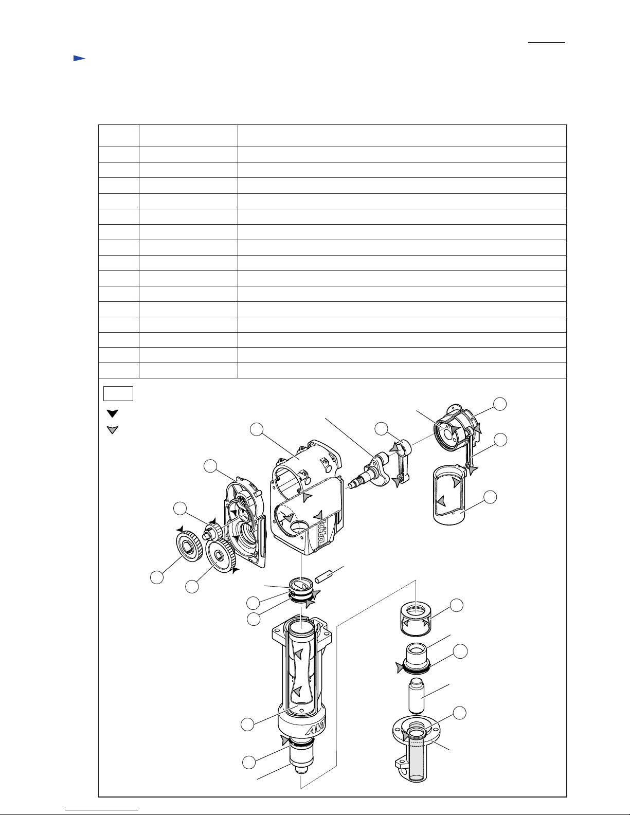
Models No.
Description
PRODUCT
Current (A)
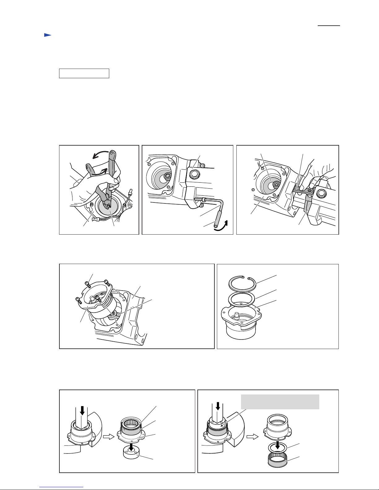
TECHNICAL INFORMATION
CONCEPT AND MAIN APPLICATIONS
Specification
Standard equipment
Optional accessories
Note: The standard equipment for the tool shown above may differ by country.
P 1 / 20
HM1810
Electric Breaker
Dimensions: mm (")
Width (W)
Height (H)
Length (L) 824 (32-1/2)
146 (5-3/4)
633 (25)
L
W
Model HM1810 has been developed as 28.6mm hex shank electric breaker
conforming to the permissible noise level limit of 2006 stage of European
Noise Directive for Outdoor Equipment.
Despite such low noise level, features highest-in-class chipping efficiency.
Also features unique Makita AVT (Anti-Vibration Technology), ensuring
incredibly low vibration.
H
Hex wrench 5 ................ 1 pc
Bull point
Cold chisel
Scaling chisel
Clay spade
Rammer
Blows per min.: bpm=min-1
Model HM1810
Protection from electric shock
Net weight: Kg (lbs)
Power supply cord: m (ft)
Noise*2:
dB(A)
*2: Noise indicates sound power level.
*3: This is the permissible noise level limit of 2006 stage of the "European Noise Directive for Outdoor
Equipment" (2000/14/EC). And in and after 2006, it will be prohibited in Europe to sell the products
with the sound power level exceeding this noise level limit.
The values of the permissible noise level limit listed above are calculated by us in accordance with the
directive. (The calculation is based on the weight of product.)
*4: Vibration level on the catalog for European countries
*1: Continuous Rating Input: Taiwan=1,570W, UK (low voltage)=1,700W, Saudi Arabia (low voltage)=1,650W
Specification
Shank: mm (")
Anti-vibration
technology
Vibration*4: m/s2
1,100
5.0 (16.4) [brazil only: 2.0m (6.6ft)]
Hex 28.6 (1-1/8)
Double insulation
Permissible noise level limit*3
Guaranteed noise level on the
catalog for European countries
Impact energy: J (catalog value) 63
Vibration absorbing handle No
Counterweight mechanism
32 (70.6)
111
No
107
8