manuals.online logo
Brands
  1. Home
  2. •
  3. Brands
  4. •
  5. Mandik
  6. •
  7. Fire And Smoke Damper
  8. •
  9. Mandik RKM User manual

Mandik RKM User manual

2
1. Description.........................................................................................................................
3
2. Design................................................................................................................................
3
3. Placement and Assembly....................................................................................................
4
4. Dimensions.........................................................................................................................
5
5. Material, surface protection.................................................................................................
9
6. Product data.......................................................................................................................
9
7. Logistic terms......................................................................................................................
9
8. Warranty.............................................................................................................................
9
9. Installation..........................................................................................................................
9
3
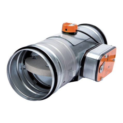
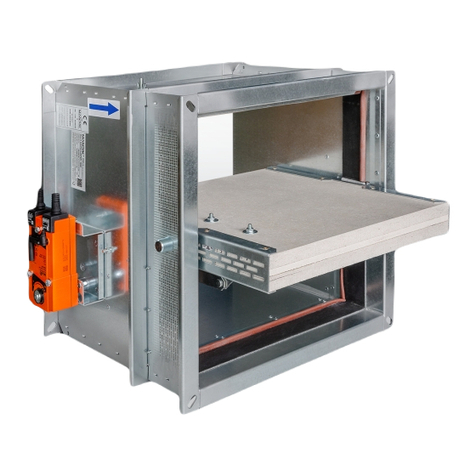
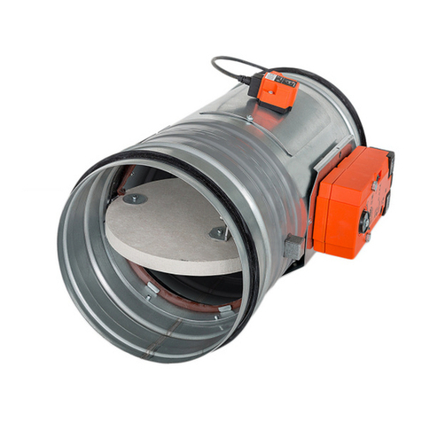
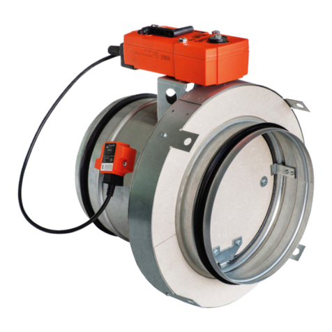
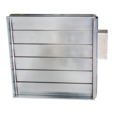
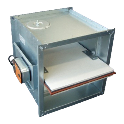
The dampers consist of blade frames and control mechanisms. It serves to regulate the air flow
by throttling the cross section.
The dampers are intended for atmospheres protected against weather influences with climatic
condition classification of class 3K5 with temperature limitation from -20°C to +50°C, without
condensation, frost, ice, without water, including from other sources than from rain acc. to EN
60721-3-3 zmA2, and for atmospheres with explosion hazard of group and category 2G Ex h IIC
T6…T3 Gb acc. to EN ISO 80079-36.
If the damper is fitted with electrical items, the temperature range shall be restricted acc. to the
temperature range of the electrical items used. Then the group of non-explosiveness of the
damper with electrical items depends on the non-explosive design of the electrical items installed
on the damper. The electrical devices installed together with the damper must be made in the
design corresponding to the given zone. The principle for determining the respective zones
specifies that it shall not be distinguished whether the specified atmosphere is inside or outside
the damper.
68°C T6
98°C T5
140°C T3
The dampers are not intended for air masses with mechanical, dusty, fibrous and sticky admixtures.
• Manual control
• Control for mounting the actuator
manual .02
for mounting the actuator* .08
4
The dampers are intended for installation in air-conditioning piping. The operation position is
arbitrary.
The minimum space for the control device is 200 mm (in blade rotation axis).
When assembling round dampers into the piping, respect the overlap of open blade "a" (tab.
4.3.1.).
5
The damper for actuator attachment is fitted with a square pin with 8 x 8 mm
cross section, onto which the actuator is to be fixed either directly or with
the help of a reducer. The pin exceeds the damper flange by 30 mm.
Position:
1 Damper body
2 Divider
3 Damper blade
4 Control mechanism
5 Control lever (manual)
6 Stiffening bolt
6
The damper for actuator attachment is fitted with a square
pin with 10x10 mm diameter and 50 mm length.
Position:
1 Damper body
2 Damper blade
3 Pin
4 Control lever (manual)
5
Control lever (mechanical)
7
are made in the following size series (A x B):
RKM (RKTM): from 200 x 200 mm to 2000 x 2000 mm
The damper length is 150 mm.
must be discussed with the manufacturer in advance:
RKM: from 100 x 100 mm to 2400 x 2400 mm
RKTM: from 100 x 100 mm to 2400 x 2000 mm
: from 80 mm to 800 mm diameter.
are not manufactured!
a
150 - 110 4 79 240 -
150 - 130 4 99 240 -
150 - 140 4 109 240 -
150 - 155 8 124 240 -
150 - 170 8 139 240 -
- - - - 149 240 -
150 - 195 8 159 240 -
150 10 215 8 179 240 -
150 20 235 8 199 240 -
150 32,5 260 8 224 240 -
150 45 285 8 249 240 -
150 60 315 8 279 240 15
150 70 335 12 299 240 25
- - - - 309 240 30
150 77,5 350 12 314 240 32
150 97,5 390 12 354 240 52
200 95 445 12 399 300 45
200 120 495 12 449 300 70
200 145 545 16 499 300 95
200 175 605 16 559 300 125
200 210 680 16 629 300 160
200 250 760 20 709 300 200
200 295 860 20 799 300 245
8
- flanges with 30 mm width are fitted with oval holes in corners
• Round piping with flanges - flanges acc. to EN 12 0505
• Spiro piping with lip seal
9
The frames, blades and control mechanism of the dampers are made of galvanized or stainless
metal sheet, respectively; the blade pins of square dampers are made of plastic, the blade pins
of round dampers are made of galvanized steel or stainless steel, respectively.
The dampers are delivered without further surface treatment.
• logo of company - manufacturer • serial number • company name and address
• type and design • year of production • size and weight
• number of technical specification • certification
Furthermore, the damper is marked with the symbol of non-explosiveness.
The dampers are transported as bulk cargo in covered means of transport. The dampers can be
transported on pallets or in crating upon accord with the customer. For handling during transport
and storage, the dampers must be protected against mechanical damage. The potential
packages will be considered non-returnable and their price will not be included in the damper price.
Unless another method of reception is specified in the purchase order, the handover of the
dampers to the forwarder shall be understood as reception.
The dampers must be stored in covered buildings, in an environment without aggressive vapours,
gases and dust. A temperature in a range of -5°C and +40°C and a relative humidity of max. 80%
must be maintained in the buildings. For handling during storage, the dampers must be protected
against mechanical damage.
The manufacturer provides a warranty of 24 months from the date of dispatch for the dampers.
If the dampers are damaged by transport, a record must be written down with the forwarder at
reception for later complaint.
The assembly of the dampers must be carried out while observing all applicable safety standards
and regulations.
Before putting the dampers into operation and during subsequent operability inspections, the
following points must be visually checked: correct incorporation of the damper, interconnection of
all metal parts and, if actuator or limit switches are attached, correct connection.
The flange and screw connections must be conductively connected during assembly, for protec-
tion against hazardous contact according to EN 332000-4-41,-4-47 and -5-54. 2 fan-shaped
washers in galvanized design are to be used for conductive connection; they are to be situated
under the head of one bolt and under the screwed nut.
The assembly consists in installation of the damper into the air-conditioning piping.
The producer reserves the right for innovations of the product. For actual product information see
www.mandik.com
MANDÍK, a.s.
Dobříšská 550
26724 Hostomice
Czech Republic
Tel.: +420 311 706 706
E-Mail: [email protected]
www.mandik.com

This manual suits for next models

3

Other Mandik Fire And Smoke Damper manuals

Mandik SEDM User manual

Mandik

Mandik SEDM User manual

Mandik FDMC User manual

Mandik

Mandik FDMC User manual

Mandik FDMC Series User manual

Mandik

Mandik FDMC Series User manual

Mandik SEDM-L User manual

Mandik

Mandik SEDM-L User manual

Mandik SEDS-R User manual

Mandik

Mandik SEDS-R User manual

Mandik SEDS-R User manual

Mandik

Mandik SEDS-R User manual

Mandik VCDM Manual

Mandik

Mandik VCDM Manual

Mandik SEDM-L Guide

Mandik

Mandik SEDM-L Guide

Mandik SEDS-L User manual

Mandik

Mandik SEDS-L User manual

Mandik FDMD User manual

Mandik

Mandik FDMD User manual

Mandik FDMA User manual

Mandik

Mandik FDMA User manual

Mandik FDMB User manual

Mandik

Mandik FDMB User manual

Mandik FDML User manual

Mandik

Mandik FDML User manual

Mandik SEDM-L User manual

Mandik

Mandik SEDM-L User manual

Mandik FDMR Manual

Mandik

Mandik FDMR Manual

Mandik SEDS-L Guide

Mandik

Mandik SEDS-L Guide

Mandik MSD Guide

Mandik

Mandik MSD Guide

Mandik SEDS User manual

Mandik

Mandik SEDS User manual

Mandik MSD User manual

Mandik

Mandik MSD User manual
Mandik FDMS Series User manual

Mandik

Mandik FDMS Series User manual

Mandik FDMD User manual

Mandik

Mandik FDMD User manual

Mandik FDMR User manual

Mandik

Mandik FDMR User manual

Mandik FDMR Guide

Mandik

Mandik FDMR Guide

Mandik SEDM Guide

Mandik

Mandik SEDM Guide

Popular Fire And Smoke Damper manuals by other brands

Trox Technik AKK Assembly and operating instructions

Trox Technik

Trox Technik AKK Assembly and operating instructions

Greenheck ES Series Installation, operation and maintenance manual

Greenheck

Greenheck ES Series Installation, operation and maintenance manual

mercor mcr PL1 Technical and Operational Documentation

mercor

mercor mcr PL1 Technical and Operational Documentation

Tamco 7000 Series Installation guidelines

Tamco

Tamco 7000 Series Installation guidelines

EKOVENT EKO-SRB1 Installation, operating and maintenance instructions

EKOVENT

EKOVENT EKO-SRB1 Installation, operating and maintenance instructions

Exodraft SVD quick guide

Exodraft

Exodraft SVD quick guide

Ace FYN-S1 Operating and mounting instructions

Ace

Ace FYN-S1 Operating and mounting instructions

Greenheck FSDR Series Installation, operation and maintenance manual

Greenheck

Greenheck FSDR Series Installation, operation and maintenance manual

Arzel Zonocity installation instructions

Arzel

Arzel Zonocity installation instructions

KOOLAIR SAFEAIR BDK60 Technical documentation

KOOLAIR

KOOLAIR SAFEAIR BDK60 Technical documentation

ETS NORD NORDfire FDMB manual

ETS NORD

ETS NORD NORDfire FDMB manual

Swegon actionair FireShield manual

Swegon

Swegon actionair FireShield manual

Greenheck MBD-15 Installation, operation and maintenance manual

Greenheck

Greenheck MBD-15 Installation, operation and maintenance manual

Broan NuTone RDFQL installation guide

Broan

Broan NuTone RDFQL installation guide

KOOLAIR FDS-3G Series manual

KOOLAIR

KOOLAIR FDS-3G Series manual

New York Blower IM-220 Installation maintenance and operating instructions

New York Blower

New York Blower IM-220 Installation maintenance and operating instructions

KOOLAIR SF Series manual

KOOLAIR

KOOLAIR SF Series manual

Schako BSK-RPR Series Additional operating instructions

Schako

Schako BSK-RPR Series Additional operating instructions

manuals.online logo
manuals.online logoBrands
  • About & Mission
  • Contact us
  • Privacy Policy
  • Terms and Conditions

Copyright 2025 Manuals.Online. All Rights Reserved.