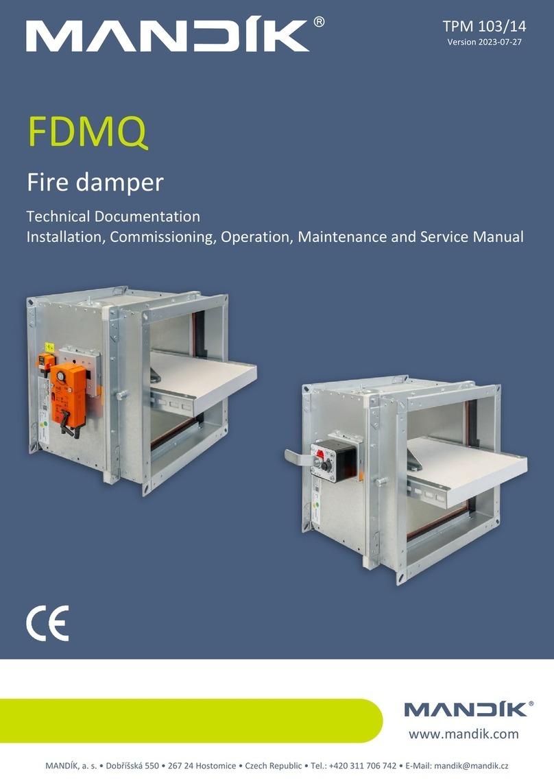
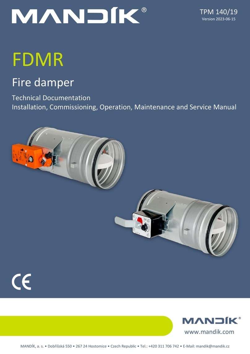
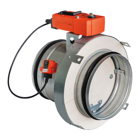
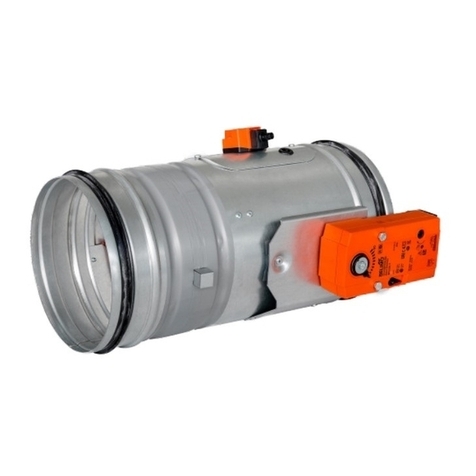
Mandik MSD Guide

www.mandik.co.uk
MANDÍK, a. s. • Dobříšská 550 • 267 24 Hostomice • Czech Republic • Tel.: +420 311 706 742 • E-Mail: [email protected]
Manufacturer
MANDIK UK Ltd • 130 Aztec West • Bristol BS32 4UB • United Kingdom • Tel.: +44 117 4526376 • E-Mail: [email protected]
Authorized representative
MSD
Multi smoke damper
Technical Documentation
Installation, Commissioning, Operation, Maintenance and Service Manual
TPM 159/22
Version 2022-12-20

MSD - multi smoke damperPage 2 Version 2022-12-20
TPM 159/22
These technical specifications state a row of manufactured sizes and models of multi smoke dampers MSD.
It is valid for production, designing, ordering, delivery, maintenance and operation.
CONTENT
I. GENERAL.....................................................................................................................................................................................3
Description..............................................................................................................................................................................3
Design.....................................................................................................................................................................................4
Design with actuating mechanism.......................................................................................................................................4
Communication and control module MDCM.......................................................................................................................9
Communication and control module MDPM.......................................................................................................................9
Dimensions...........................................................................................................................................................................10
Technical parameters............................................................................................................................................................12
Placement and Assembly......................................................................................................................................................17
Statement of installations.....................................................................................................................................................18
Installation in solid wall construction SINGLE / MULTI......................................................................................................19
Installation in gypsum wall SINGLE / MULTI......................................................................................................................22
Installation in solid ceiling construction SINGLE / MULTI..................................................................................................25
Installation in solid ceiling construction MULTI / MULTI...................................................................................................26
Suspension systems..............................................................................................................................................................27
Duct connection....................................................................................................................................................................31
MSD installed in fire separating construction and connection to steel duct.....................................................................32
MSD installed in steel duct with insulation.......................................................................................................................38
II. TECHNICAL DATA.....................................................................................................................................................................39
Pressure loss.........................................................................................................................................................................39
Noise data.............................................................................................................................................................................41
III. MATERIAL, FINISHING.............................................................................................................................................................42
Material................................................................................................................................................................................42
IV. INSPECTION, TESTING.............................................................................................................................................................42
V. TRANSPORTATION AND STORAGE...........................................................................................................................................43
Logistic terms........................................................................................................................................................................43
VI. ASSEMBLY, ATTENDANCE AND MAINTENANCE......................................................................................................................43
Assembly...............................................................................................................................................................................43
Electrical connection of the actuator in protection box....................................................................................................44
Connection of the control module MDPM & MDCM interfaces inside protection box.....................................................45
Entry into service and revisions.........................................................................................................................................46
Spare parts.........................................................................................................................................................................46
VII. PRODUCT DATA.....................................................................................................................................................................47
Data label..............................................................................................................................................................................47
VIII. ORDERING INFORMATION....................................................................................................................................................47
Ordering key.........................................................................................................................................................................47
Methods of damper installation, according to design.......................................................................................................48
Page 3Version 2022-12-20 MSD - multi smoke damper
TPM 159/22
I. GENERAL
Description
Damper characteristics
■CE certified acc. to EN 12101-8
■Tested in accordance with EN 1366-10
■Classified acc. to EN 13501-4+A1
■External Casing leakage class min. C acc. to EN 1751
■Internal leakage min. class 2, for max. dimension 1500 x 800 mm min. class 3 acc. to EN 1751
■Cycling test in class Cmod acc. to EN 12101-8
■Certificate of constancy of performance UKCA No. 0832-UKCA-CPR-P1009 & UKNI No. 0832-UKNI-CPR-P1004
■Certificate of constancy of performance CE No. 1391-CPR-2021/0084
■Declaration of Perfomance UKCA & UKNI No. PM/MSD/02/22/1
■Declaration of Perfomance CE No. PM/MSD/01/22/3
■Hygienic assessment of fire dampers - Report No. 1.6/pos/19/19c
Working conditions
■Exact damper function is provided under the following conditions
■maximum air velocity 15 m/s
■underpressure max. -1500 Pa or overpressure max. 500 Pa
■Dampers can be installed in arbitrary position (horizontal or vertical blade axis).
■Dampers are designed for macroclimatic areas with mild climate according to EN 60 721-3-3.
■Temperature in the place of installation is permitted to range from -30°C to +50°C.
Classification of Dampers
Supporting construction Installation type / system Classification
Horizontal or vertical duct system Damper installed into a duct EI 120 (ved-hod i↔o) S1500CmodHOT400/30AAmulti
Damper installed on the end of a duct with grille
Solid wall construction
- 125 mm min. wall thickness Mortar or gypsum EI 120 (vew i↔o) S1500CmodHOT400/30AAmulti
Solid wall construction
- 100 mm min. wall thickness Ablative Coated Batt EI 90 (vew i↔o) S1500CmodHOT400/30AAmulti
Gypsum plasterboard wall
- 125 mm min. wall thickness Mortar or gypsum EI 120 (vew i↔o) S1500CmodHOT400/30AAmulti
Gypsum plasterboard wall
- 100 mm min. wall thickness Ablative Coated Batt EI 90 (vew i↔o) S1500CmodHOT400/30AAmulti
Solid ceiling construction
- 150 mm min. ceiling thickness
Mortar or gypsum EI 120 (how i↔o) S1500CmodHOT400/30AAmulti
Ablative Coated Batt EI 90 (how i↔o) S1500CmodHOT400/30AAmulti
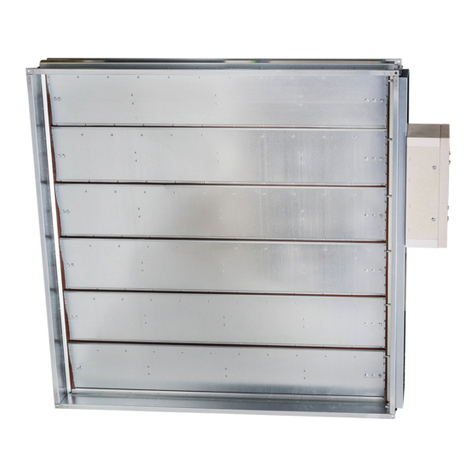
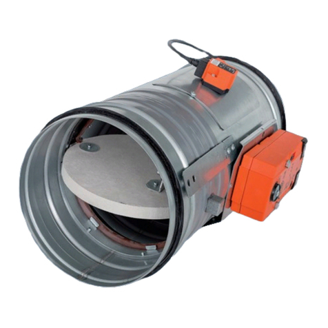
Smoke extraction dampers - MSD are designed into an inlet or
extract smoke ventilation system. The dampers are designed either
to close to provide compartmentalization or to open (for fresh air
inlet) or to allow removal of the heat and combustible products from
a fire in the affected fire zone/compartment.
The damper blade is controlled by electrical actuating mechanism.
Dampers are fire resistant and are intended for systems with
automatic activation.
Dampers are designed for using in fire compartments that can be
connected to the smoke exhaust ducts (tested according to EN
1366-8) or they can be installed in or on the construction of the fire
compartment. Damper MSD

MSD - multi smoke damperPage 4 Version 2022-12-20
TPM 159/22
Design
Design with actuating mechanism
■Belimo actuators are used for dampers, series BEN, BEE,
BE for 230V AC resp. 24 V AC/DC, Schischek InMax 50.75-S
actuators (universal 24V or 230V supply) are used for
large size of dampers.
■After connection to the power supply voltage, the
actuator moves the damper blade to the "OPEN" position
or "CLOSED" (according to the corresponding connection,
see wiring diagram). If the power supply is interrupted,
the actuator stops at the current position. The signalling
of the "OPEN" and "CLOSED" damper blade positions is
ensured by two built-in fixed “potential-free” end- limit
switches.
■The actuator for operating the damper blade is mounted
in an insulated cover/box. It is accessible after removing
the cover lid. The electrical connection of the actuator is
made with a non-flammable cable (or a cable located in
the adjoining cable duct), which passes through an
opening made in the wall of the insulated cover/box when
installing the damper or when connecting the actuator
power cable. The power and control cable must be CAT 3
as BS EN8519.
Design .44 and .54
■Belimo modulating actuators, BEN (BEE)-SR series for 24V
AC/DC are specially designed for remote control of fire
dampers. The position of the damper blade is adjustable
by means of control voltage 0 (2)...10V DC.
■The signalling of the "OPEN" and "CLOSED" damper blade
positions is ensured by two built-in fixed “potential-free”
limit switches.
■The actuator for operating the damper blade is mounted
in an insulated cover/box. It is accessible after removing
the cover lid. The electrical connection of the actuator is
made with non-flammable cables (or cables located in the
adjoining cable duct), which pass through an opening
made in the wall of the insulated cover when installing the
damper or when connecting the power cables of the
actuator. The power and control cable must be CAT 3 as
BS EN8519.
Design .65
Design .44, .54 and .65
Actuating mechanism

Page 5Version 2022-12-20 MSD - multi smoke damper
TPM 159/22
Actuator BELIMO BEN 24(-ST) Actuator BELIMO BEN 24-SR
S2S1 S3 S5S4 S6
2
13
<5° <80°
Actuator BELIMO BEN 230
S2S1 S3 S5S4 S6
2
13
<5° <80°
N L1
Actuator BELIMO BEN 24(-ST), BEN 24-SR, BEN 230
Actuator BELIMO - 15 Nm BEN 24(-ST) BEN 24-SR* BEN 230
Power voltage AC/DC 24 V
50/60Hz
AC/DC 24 V
50/60Hz
AC 230 V
50/60Hz
Power consumption - in operation
- in the end position
3 W
0,1 W
3 W
0,3 W
4 W
0,4 W
Dimensioning 6 VA (Imax 8,2 A @ 5 ms) 6,5 VA (Imax 8.2 A @ 5 ms) 7 VA (Imax 4 A @ 5 ms)
Protection class III III II
Degree of protection IP 54
Adjustment time for 95° < 30 s
Ambient temperature
Storage temperature
-30°C … +55°C
-40°C … +80°C
Connection - drive
- auxiliary switch
Cable 1 m, 3 x 0,75 mm2
Cable 1 m, 6 x 0,75 mm2
(BEN 24-ST) with plug
connectors
Cable 1 m, 4 x 0,75 mm2
Cable 1 m, 6 x 0,75 mm2
Cable 1 m, 3 x 0,75 mm2
Cable 1 m, 6 x 0,75 mm2
* Only available for 24V and selected damper sizes
S2S1 S3 S5S4 S6
2
13
<5° <80°
5
Y
U
DC (0)2...10 V
DC 2...10 V
Extended leads are not possible with smoke control dampers
as the belimo cabls are not fire rated to a high Field wiring must
be brought into and terminated within the damper housing.
For more detail → see pages 43 to 45, paragraph Assembly.
BELIMO - 15 N.m

MSD - multi smoke damperPage 6 Version 2022-12-20
TPM 159/22
Actuator BELIMO BEE 24(-ST)
Actuator BELIMO BEE 230
Actuator BELIMO BEE 24(-ST), BEE 24-SR, BEE 230
Actuator BELIMO - 25 Nm BEE 24(-ST) BEE 24-SR* BEE 230
Power voltage AC/DC 24 V
50/60Hz
AC/DC 24 V
50/60Hz
AC 230 V
50/60Hz
Power consumption - in operation
- in the end position
2,5 W
0,1 W
3 W
0,3 W
3,5 W
0,4 W
Dimensioning 5 VA (Imax 8,2 A @ 5 ms) 5,5 VA (Imax 8.2 A @ 5 ms) 6 VA (Imax 4 A @ 5 ms)
Protection class III III II
Degree of protection IP 54
Adjustment time for 95° < 60 s
Ambient temperature
Storage temperature
-30°C … +55°C
-40°C … +80°C
Connection - drive
- auxiliary switch
Cable 1 m, 3 x 0,75 mm2
Cable 1 m, 6 x 0,75 mm2
(BEE 24-ST) with plug
connectors
Cable 1 m, 4 x 0,75 mm2
Cable 1 m, 6 x 0,75 mm2
Cable 1 m, 3 x 0,75 mm2
Cable 1 m, 6 x 0,75 mm2
S2S1 S3 S5S4 S6
2
13
<5° <80°
S2S1 S3 S5S4 S6
2
13
<5° <80°
N L1
* Only available for 24V and selected damper sizes
Actuator BELIMO BEE 24-SR
S2S1 S3 S5S4 S6
2
13
<5° <80°
5
Y
U
DC (0)2...10 V
DC 2...10 V
BELIMO - 25 N.m
Extended leads are not possible with smoke control dampers
as the belimo cabls are not fire rated to a high Field wiring must
be brought into and terminated within the damper housing.
For more detail → see pages 43 to 45, paragraph Assembly.

Page 7Version 2022-12-20 MSD - multi smoke damper
TPM 159/22
Actuator BELIMO BE 24-12(-ST)
Actuator BELIMO BE 230-12
Actuator BELIMO BE 24-12(-ST), BE 230-12
Actuator BELIMO - 40 Nm BE 24-12(-ST) BE 230-12
Power voltage AC/DC 24 V
50/60Hz
AC 230 V
50/60Hz
Power consumption - in operation
- in the end position
12 W
0,5 W
8 W
0,5 W
Dimensioning 18 VA (Imax 8,2 A @ 5 ms) 15 VA (Imax 7.9 A @ 5 ms)
Protection class III II
Degree of protection IP 54
Adjustment time for 95° < 60 s
Ambient temperature
Storage temperature
-30°C … +55°C
-40°C … +80°C
Connection - drive
- auxiliary switch
Cable 1 m, 3 x 0,75 mm2
Cable 1 m, 6 x 0,75 mm2
(BE 24-ST) with plug connectors
S2S1 S3 S5S4 S6
2
13
<3° <87°
S2S1 S3 S5S4 S6
2
13
<3° <87°
N L1
BELIMO - 40 N.m
Extended leads are not possible with smoke control dampers
as the belimo cabls are not fire rated to a high Field wiring must
be brought into and terminated within the damper housing.
For more detail → see pages 43 to 45, paragraph Assembly.

MSD - multi smoke damperPage 8 Version 2022-12-20
TPM 159/22
Actuator SCHISCHEK InMax 50.75-S
Power voltage 24-240 VAC/DC
50/60Hz
Power consumption - motoring
- heating
10 W
16 W (start at -20°C)
Protection class I
Degree of protection IP 66
Adjustment time for 95° < 60 s
Ambient temperature
Storage temperature
-40°C … +50°C
-40°C … +70°C
Connection Cable 1 m, 0,5 mm2
12 3 4
24...230 VAC/DC
~
+-
12 3 4 5 6
heater
PA
~>85°
<5°
PE
Integrated aux. switches
max 24V/3A, 240V/0,25A switching
at 5° and 85°.
SCHISCHEK- 50 / 75 N.m
Extended leads are not possible with smoke control dampers
as the belimo cabls are not fire rated to a high Field wiring must
be brought into and terminated within the damper housing.
For more detail → see pages 43 to 45, paragraph Assembly.

Page 9Version 2022-12-20 MSD - multi smoke damper
TPM 159/22
■The MDCM damper control module is connected on a bi
directional communication loop back to a control panel, typically
located at the FCC.
■Each MDCM has a 230v local spur to power the damper actuator.
■Up to 96x MDCM's can be connected on one loop and multiple
loops can be incorporated.
■With an MA or AA system the MDCM's are mounted in a fire
rated and tested Ca-Si housing to BS EN1366-10.
■The MDPM damper control module is a combined control
module and damper positioning module to provide a
balanced/3R position.
■It is connected on a bi directional communication loop back to a
control panel.
■Each MDPM has a 230v local spur for powering the damper
actuator, located at the FCC.
■Up to 96x MDPM's can be connected on one loop and multiple
loops can be incorporated.
■With an MA or AA system the MDPM's are mounted in a fire
rated and tested Ca-Si housing to BS EN1366-10.
OVERRIDE MDCM
6 5 4 3 2 1 L N N L+ +
MOTOR POWERCOMMS
S S - -
F1
S5
S6
S4
S3
S2
S1
COMMS
OPEN
CLOSED
COMMAND
L
L
N L
+
S90C CONTROLLER
S90 mounted in an addressablesmoke
control damper control panel to BS
ISO 21927-9
Cable glands
Comms cable
Damper control module PCB mounted on plastic rail
Earth stud
230v 50hz 3A fused supply (by others)
Switches 6 core
Drive open / close 230v
Damper actuator
Power 3 core
Comms IN
Comms OUT
Communications loop cable CAT 3 or equivalent 1.5mm2 2 core screened
MDCM
160mm x 160mm x 62mm deep steel
enclosure powder coated red - IP54
-
56
+-
78
S E
N L L E
INSULATED
TERMINAL
USEAN
N N
NCNO
6 5 4 3 2 1 L L
J7
N
NCNO J7
OVERRIDE MDPM
6 5 4 3 2 1 L L+ +
J5J1- COMMS
S S - -
F1
S5
S6
S4
S3
S2
S1
COMMS
OPEN
CLOSED
COMMAND
OPEN
CLOSED
COMMAND
OVERRIDE
Cable glands
Comms cable Switches 6 core
Drive open / close 230v
Damper actuator
Power 3 core
Comms IN
Comms OUT
Damper control module PCB
mounted on plastic rail
+
S90C CONTROLLER
S90 mounted in an addressablesmoke
control damper control panel to BS
ISO 21927-9
-
56
+-
78
S E
Earth stud
230v 50hz 3A fused
supply (by others)
Communications loop cable CAT 3 or equivalent 1.5mm2 2 core screened
MDPM
230mm x 160mm x 62mm deep steel
enclosure powder coated red - IP54
Details of connection of the control module
interfaces inside protection box → see page 45
Details of connection of the control module
interfaces inside protection box → see page 45
Communication and control module MDCM
Communication and control module MDPM

MSD - multi smoke damperPage 10 Version 2022-12-20
TPM 159/22
Dimensions
MSD with actuating mechanism
1
MSD - design „A‟ → see pages 47 to 48
2 Actuating mechanism
3 Damper blade
4 Access door/ inspection cover
X =
94mm - BEN
98mm - BEE
115,2mm - BE
151mm - SCHISCHEK
375
A
B
X
MSD with actuating mechanism, protective cladding boards and insulation box
1
MSD - design „IB1‟ → see pages 47 to 48
2 Insulation box
3 Damper blade
4 Access door/ inspection cover
5 Protective cladding boards
X
Y
Z
375
A
B
X =
168mm - BEN (BEE)
171mm - BE
220mm - SCHISCHEK
Y =
250mm - BEN (BEE)
260mm - BE
260mm - SCHISCHEK
Z =
300mm - BEN (BEE)
370mm - BE
430mm - SCHISCHEK

Page 11Version 2022-12-20 MSD - multi smoke damper
TPM 159/22
MSD with actuating mechanism and insulation box
1
MSD - design „IB‟ → see pages 47 to 48
2 Insulation box
3 Damper blade
4 Access door/ inspection cover
X =
168mm - BEN (BEE)
171mm - BE
220mm - SCHISCHEK
Y =
250mm - BEN (BEE)
260mm - BE
260mm - SCHISCHEK
Z =
300mm - BEN (BEE)
370mm - BE
430mm - SCHISCHEK
X
Y
Z
375
A
B
Damper blade overlaps
■Open damper blade overlaps the damper body by the
value “c” or “a” and “c”. These values are specified in
chapter Technical parameters → see pages 12 to 16.
c a
Values "a" and "c" has to be respected when
projecting related smoke exhaust ducts.
Flange with corner hole
Flanges of dampers are 30 mm wide with oval hole.

MSD - multi smoke damperPage 12 Version 2022-12-20
TPM 159/22
Technical parameters
A x B
[mm]
Damper blade
overlaps
Effective
area Sef
[m2]
Weight
[kg]
Actuating
mechanism
type
A x B
[mm]
Damper blade
overlaps
Effective
area Sef
[m2]
Weight
[kg]
Actuating
mechanism
type
a
[mm]
c
[mm]
a
[mm]
c
[mm]
160
x
180 – 19 0,0162 12,2
BELIMO BEN
(15 N.m)
200
x
600 – 229 0,0984 22,4
BELIMO BEN
(15 N.m)
200 – 29 0,0191 12,6 630 – 244 0,1040 23,1
225 – 41,5 0,0228 13,1 650 9 254 0,1077 23,5
250 – 54 0,0264 13,6 700 34 279 0,1169 24,6
280 – 69 0,0307 14,3 710 39 284 0,1188 24,9
300 – 79 0,0336 14,7 750 59 304 0,1262 25,8
315 – 86,5 0,0358 15 800 84 329 0,1354 26,9
355 –
106,5
0,0416 15,8
225
x
180 – 19 0,0235 13,4
400 – 129 0,0481 16,8 200 – 29 0,0277 13,8
450 – 154 0,0554 17,8 225 – 41,5 0,0330 14,4
500 – 179 0,0626 18,8 250 – 54 0,0382 15
550 – 204 0,0699 19,9 280 – 69 0,0445 15,7
560 – 209 0,0713 20,1 300 – 79 0,0487 16,2
600 – 229 0,0771 20,9 315 – 87 0,0519 16,6
630 – 244 0,0815 21,5 355 – 86,5 0,0603 17,5
650 9 254 0,0844 21,9 400 –
106,5
0,0697 18,6
700 34 279 0,0916 23 450 – 154 0,0802 19,7
710 39 284 0,0931 23,2 500 – 179 0,0907 20,9
750 59 304 0,0989 24 550 – 204 0,1012 22,1
800 84 329 0,1061 25 560 – 209 0,1033 22,3
180
x
180 – 19 0,0185 12,6 600 – 229 0,1117 23,3
200 – 29 0,0218 13 630 – 244 0,1180 24
225 – 41,5 0,0259 13,5 650 9 254 0,1222 24,4
250 – 54 0,0300 14,1 700 34 279 0,1327 25,6
280 – 69 0,0350 14,7 710 39 284 0,1348 25,9
300 – 79 0,0383 15,2 750 59 304 0,1432 26,8
315 – 86,5 0,0408 15,5 800 84 329 0,1537 28
355 –
106,5
0,0474 16,3
250
x
180 – 19 0,0263 13,8
400 – 129 0,0548 17,3 200 – 29 0,0310 14,3
450 – 154 0,0630 18,4 225 – 41,5 0,0369 14,9
500 – 179 0,0713 19,5 250 – 54 0,0428 15,6
550 – 204 0,0795 20,6 280 – 69 0,0498 16,3
560 – 209 0,0812 20,8 300 – 79 0,0545 16,8
600 – 229 0,0878 21,6 315 – 86,5 0,0580 17,1
630 – 244 0,0927 22,3 355 –
106,5
0,0674 18,1
650 9 254 0,0960 22,7 400 – 129 0,0780 19,2
700 34 279 0,1043 23,8 450 – 154 0,0898 20,4
710 39 284 0,1059 24 500 – 179 0,1015 21,7
750 59 304 0,1125 24,9 550 – 204 0,1133 22,9
800 84 329 0,1208 26 560 – 209 0,1156 23,1
200
x
180 – 19 0,0207 12,9 600 – 229 0,1250 24,1
200 – 29 0,0244 13,4 630 – 244 0,1321 24,8
225 – 41,5 0,0290 13,9 650 9 254 0,1368 25,3
250 – 54 0,0337 14,5 700 34 279 0,1485 26,6
280 – 69 0,0392 15,2 710 39 284 0,1509 26,8
300 – 79 0,0429 15,6 750 59 304 0,1603 27,8
315 – 86,5 0,0457 16 800 84 329 0,1720 29
355 –
106,5
0,0531 16,9
280
x
180 – 19 0,0297 14,4
400 – 129 0,0614 17,9 200 – 29 0,0350 14,9
450 – 154 0,0707 19 225 – 41,5 0,0416 15,5
500 – 179 0,0799 20,1 250 – 54 0,0482 16,2
550 – 204 0,0892 21,3 280 – 69 0,0562 16,9
560 – 209 0,0910 21,5 300 – 79 0,0615 17,5
Sizes listed within the maximum/minimum sizes can be manufactured on request.

Page 13Version 2022-12-20 MSD - multi smoke damper
TPM 159/22
A x B
[mm]
Damper blade
overlaps
Effective
area Sef
[m2]
Weight
[kg]
Actuating
mechanism
type
A x B
[mm]
Damper blade
overlaps
Effective
area Sef
[m2]
Weight
[kg]
Actuating
mechanism
type
a
[mm]
c
[mm]
a
[mm]
c
[mm]
280
x
315 – 86,5 0,0655 17,8
BELIMO BEN
(15 N.m)
355
x
200 – 29 0,0449 16,3
BELIMO BEN
(15 N.m)
355 –
106,5
0,0761 18,9 225 – 41,5 0,0534 17
400 – 129 0,0880 20 250 – 54 0,0619 17,7
450 – 154 0,1012 21,3 280 – 69 0,0721 18,6
500 – 179 0,1145 22,6 300 – 79 0,0789 19,2
550 – 204 0,1277 23,8 315 – 86,5 0,0840 19,6
560 – 209 0,1304 24,1 355 –
106,5
0,0976 20,7
600 – 229 0,1410 25,1 400 – 129 0,1129 22
630 – 244 0,1489 25,9 450 – 154 0,1299 23,4
650 9 254 0,1542 26,4 500 – 179 0,1469 24,8
700 34 279 0,1675 27,7 550 – 204 0,1639 26,2
710 39 284 0,1701 27,9 560 – 209 0,1673 26,5
750 59 304 0,1807 28,9 600 – 229 0,1809 27,6
800 84 329 0,1940 30,2 630 – 244 0,1911 28,5
300
x
180 – 19 0,0319 14,7 650 9 254 0,1979 29
200 – 29 0,0376 15,3 700 34 279 0,2149 30,5
225 – 41,5 0,0447 15,9 710 39 284 0,2183 30,7
250 – 54 0,0519 16,6 750 59 304 0,2319 31,9
280 – 69 0,0604 17,4 800 84 329 0,2489 34,3
BELIMO BEE (25 N.m)
300 – 79 0,0661 17,9
400
x
180 – 19 0,0431 16,5
BELIMO BEN
(15 N.m)
315 – 86,5 0,0704 18,3 200 – 29 0,0508 17,2
355 –
106,5
0,0818 19,4 225 – 41,5 0,0604 17,9
400 – 129 0,0946 20,5 250 – 54 0,0701 18,7
450 – 154 0,1089 21,8 280 – 69 0,0816 19,6
500 – 179 0,1231 23,2 300 – 79 0,0893 20,2
550 – 204 0,1374 24,5 315 – 86,5 0,0951 20,6
560 – 209 0,1402 24,7 355 –
106,5
0,1105 21,8
600 – 229 0,1516 25,8 400 – 129 0,1278 23,2
630 – 244 0,1602 26,6 450 – 154 0,1471 24,7
650 9 254 0,1659 27,1 500 – 179 0,1663 26,2
700 34 279 0,1801 28,4 550 – 204 0,1856 27,6
710 39 284 0,1830 28,7 560 – 209 0,1894 27,9
750 59 304 0,1944 29,7 600 – 229 0,2048 29,1
800 84 329 0,2086 31 630 – 244 0,2164 30
315
x
180 – 19 0,0336 15 650 9 254 0,2241 30,6
200 – 29 0,0396 15,6 700 34 279 0,2433 32,1
225 – 41,5 0,0471 16,2 710 39 284 0,2472 32,4
250 – 54 0,0546 16,9 750 59 304 0,2626 33,6
280 – 69 0,0636 17,7 800 84 329 0,2818 36,1
BELIMO BEE (25 N.m)
300 – 79 0,0696 18,3
450
x
180 – 19 0,0487 17,5
BELIMO BEN
(15 N.m)
315 – 86,5 0,0741 18,7 200 – 29 0,0574 18,1
355 –
106,5
0,0861 19,7 225 – 41,5 0,0683 18,9
400 – 129 0,0996 20,9 250 – 54 0,0792 19,7
450 – 154 0,1146 22,3 280 – 69 0,0922 20,7
500 – 179 0,1296 23,6 300 – 79 0,1009 21,3
550 – 204 0,1446 24,9 315 – 86,5 0,1074 21,8
560 – 209 0,1476 25,2 355 –
106,5
0,1248 23,1
600 – 229 0,1596 26,3 400 – 129 0,1444 24,5
630 – 244 0,1686 27,1 450 – 154 0,1662 26,1
650 9 254 0,1746 27,6 500 – 179 0,1879 27,6
700 34 279 0,1896 29 550 – 204 0,2097 29,2
710 39 284 0,1926 29,2 560 – 209 0,2140 29,5
750 59 304 0,2046 30,3 600 – 229 0,2314 30,8
800 84 329 0,2196 31,6 630 – 244 0,2445 31,8
355
x
180 – 19 0,0381 15,7 650 9 254 0,2532 32,4
Sizes listed within the maximum/minimum sizes can be manufactured on request.

MSD - multi smoke damperPage 14 Version 2022-12-20
TPM 159/22
A x B
[mm]
Damper blade
overlaps
Effective
area Sef
[m2]
Weight
[kg]
Actuating
mechanism
type
A x B
[mm]
Damper blade
overlaps
Effective
area Sef
[m2]
Weight
[kg]
Actuating
mechanism
type
a
[mm]
c
[mm]
a
[mm]
c
[mm]
450
x
700 34 279 0,2749 34 BELIMO BEN
(15 N.m)
560
x
550 – 204 0,2627 32,7
BELIMO BEN
(15 N.m)
710 39 284 0,2793 34,3 560 – 209 0,2681 33,1
750 59 304 0,2967 35,6 600 – 229 0,2899 34,5
800 84 329 0,3184 38,2
BELIMO BEE (25 N.m)
630 – 244 0,3063 35,6
500
x
180 – 19 0,0543 18,4
BELIMO BEN
(15 N.m)
650 9 254 0,3172 36,3
200 – 29 0,0640 19,1 700 34 279 0,3444 38,1
225 – 41,5 0,0761 19,9 710 39 284 0,3499 38,4
250 – 54 0,0883 20,8 750 59 304 0,3717 40,9 BELIMO BEE
(25 N.m)
280 – 69 0,1028 21,8 800 84 329 0,3989 42,6
300 – 79 0,1125 22,5
600
x
180 – 19 0,0655 20,2
BELIMO BEN
(15 N.m)
315 – 86,5 0,1198 23 200 – 29 0,0772 21
355 –
106,5
0,1392 24,3 225 – 41,5 0,0918 21,9
400 – 129 0,1610 25,8 250 – 54 0,1065 22,9
450 – 154 0,1853 27,5 280 – 69 0,1240 24
500 – 179 0,2095 29,1 300 – 79 0,1357 24,7
550 – 204 0,2338 30,8 315 – 86,5 0,1445 25,3
560 – 209 0,2386 31,2 355 –
106,5
0,1679 26,8
600 – 229 0,2580 32,5 400 – 129 0,1942 28,4
630 – 244 0,2726 33,5 450 – 154 0,2235 30,3
650 9 254 0,2823 34,2 500 – 179 0,2527 32,1
700 34 279 0,3065 35,8 550 – 204 0,2820 34
710 39 284 0,3114 36,2 560 – 209 0,2878 34,4
750 59 304 0,3308 37,5 600 – 229 0,3112 35,8
800 84 329 0,3550 40,2
BELIMO BEE (25 N.m)
630 – 244 0,3288 37
550
x
180 – 19 0,0599 19,3
BELIMO BEN
(15 N.m)
650 9 254 0,3405 37,7
200 – 29 0,0706 20 700 34 279 0,3697 39,5
225 – 41,5 0,0840 20,9 710 39 284 0,3756 40,9 BELIMO BEE
(25 N.m)
250 – 54 0,0974 21,8 750 59 304 0,3990 42,4
280 – 69 0,1134 22,9 800 84 329 0,4282 44,3
300 – 79 0,1241 23,6
630
x
180 – 19 0,0689 20,7
BELIMO BEN
(15 N.m)
315 – 86,5 0,1321 24,1 200 – 29 0,0812 21,6
355 –
106,5
0,1535 25,5 225 – 41,5 0,0966 22,5
400 – 129 0,1776 27,1 250 – 54 0,1119 23,5
450 – 154 0,2044 28,9 280 – 69 0,1304 24,6
500 – 179 0,2311 30,6 300 – 79 0,1427 25,4
550 – 204 0,2579 32,4 315 – 86,5 0,1519 26
560 – 209 0,2632 32,8 355 –
106,5
0,1765 27,5
600 – 229 0,2846 34,2 400 – 129 0,2042 29,2
630 – 244 0,3007 35,2 450 – 154 0,2349 31,1
650 9 254 0,3114 35,9 500 – 179 0,2657 33
700 34 279 0,3381 37,7 550 – 204 0,2964 34,9
710 39 284 0,3435 38 560 – 209 0,3026 35,3
750 59 304 0,3649 40,5 BELIMO BEE
(25 N.m)
600 – 229 0,3272 36,8
800 84 329 0,3916 42,2 630 – 244 0,3456 38
560
x
180 – 19 0,0610 19,4
BELIMO BEN
(15 N.m)
650 9 254 0,3579 38,8
200 – 29 0,0719 20,2 700 34 279 0,3887 40,7
225 – 41,5 0,0856 21,1 710 39 284 0,3948 42,1 BELIMO BEE
(25 N.m)
250 – 54 0,0992 22 750 59 304 0,4194 43,6
280 – 69 0,1155 23,1 800 84 329 0,4502 45,5
BELIMO BE (40 N.m)
300 – 79 0,1264 23,8
650
x
180 – 19 0,0711 21,1
BELIMO BEN
(15 N.m)
315 – 86,5 0,1346 24,4 200 – 29 0,0838 21,9
355 –
106,5
0,1564 25,8 225 – 41,5 0,0997 23
400 – 129 0,1809 27,4 250 – 54 0,1156 23,9
450 – 154 0,2082 29,2 280 – 69 0,1346 25,1
500 – 179 0,2354 30,9 300 – 79 0,1473 25,9
Sizes listed within the maximum/minimum sizes can be manufactured on request.

Page 15Version 2022-12-20 MSD - multi smoke damper
TPM 159/22
A x B
[mm]
Damper blade
overlaps
Effective
area Sef
[m2]
Weight
[kg]
Actuating
mechanism
type
A x B
[mm]
Damper blade
overlaps
Effective
area Sef
[m2]
Weight
[kg]
Actuating
mechanism
type
a
[mm]
c
[mm]
a
[mm]
c
[mm]
650
x
315 – 86,5 0,1568 26,4
BELIMO BEN
(15 N.m)
750
x
200 – 29 0,0970 23,8
BELIMO BEN
(15 N.m)
355 –
106,5
0,1822 28 225 – 41,5 0,1154 25
400 – 129 0,2108 29,7 250 – 54 0,1338 26
450 – 154 0,2426 31,7 280 – 69 0,1558 27,3
500 – 179 0,2743 33,6 300 – 79 0,1705 28,1
550 – 204 0,3061 35,6 315 – 86,5 0,1815 28,8
560 – 209 0,3124 36 355 –
106,5
0,2109 30,5
600 – 229 0,3378 37,5 400 – 129 0,2440 32,4
630 – 244 0,3569 38,7 450 – 154 0,2808 34,5
650 9 254 0,3696 39,5 500 – 179 0,3175 36,6
700 34 279 0,4013 42,4 BELIMO BEE
(25 N.m)
550 – 204 0,3543 38,7
710 39 284 0,4077 42,8 560 – 209 0,3616 39,2
750 59 304 0,4331 44,4 600 – 229 0,3910 40,9
800 84 329 0,4648 46,3
BELIMO BE (40 N.m)
630 – 244 0,4131 42,1
700
x
180 – 19 0,0767 22
BELIMO BEN
(15 N.m)
650 9 254 0,4278 44 BELIMO BEE
(25 N.m)
200 – 29 0,0904 22,9 700 34 279 0,4645 46,1
225 – 41,5 0,1075 24 710 39 284 0,4719 46,6
250 – 54 0,1247 25 750 59 304 0,5013 48,3 BELIMO BE
(40 N.m)
280 – 69 0,1452 26,2 800 84 329 0,5380 50,4
300 – 79 0,1589 27
800
x
180 – 19 0,0879 23,8
BELIMO BEN
(15 N.m)
315 – 86,5 0,1692 27,6 200 – 29 0,1036 24,8
355 –
106,5
0,1966 29,2 225 – 41,5 0,1232 26
400 – 129 0,2274 31,1 250 – 54 0,1429 27,1
450 – 154 0,2617 33,1 280 – 69 0,1664 28,4
500 – 179 0,2959 35,1 300 – 79 0,1821 29,3
550 – 204 0,3302 37,2 315 – 86,5 0,1939 29,9
560 – 209 0,3370 37,6 355 –
106,5
0,2253 31,7
600 – 229 0,3644 39,2 400 – 129 0,2606 33,7
630 – 244 0,3850 40,4 450 – 154 0,2999 35,9
650 9 254 0,3987 42,2
BELIMO BEE
(25 N.m)
500 – 179 0,3391 38,1
700 34 279 0,4329 44,3 550 – 204 0,3784 40,3
710 39 284 0,4398 44,7 560 – 209 0,3862 40,8
750 59 304 0,4672 46,3 600 – 229 0,4176 42,5
800 84 329 0,5014 48,3
BELIMO BE (40 N.m)
630 – 244 0,4412 44,9 BELIMO BEE
(25 N.m)
710
x
180 – 19 0,0778 22,2
BELIMO BEN
(15 N.m)
650 9 254 0,4569 45,8
200 – 29 0,0917 23,1 700 34 279 0,4961 48
225 – 42 0,1091 24,2 710 39 284 0,5040 48,4 BELIMO BE
(40 N.m)
250 – 54 0,1265 25,2 750 59 304 0,5354 50,2
280 – 69 0,1473 26,4 800 84 329 0,5746 52,4
300 – 79 0,1612 27,2
900
x
180 – 19 0,0991 25,6
BELIMO BEN
(15 N.m)
315 – 86,5 0,1717 27,8 200 – 29 0,1168 26,7
355 –
106,5
0,1995 29,5 225 – 41,5 0,1389 28
400 – 129 0,2307 31,3 250 – 54 0,1611 29,2
450 – 154 0,2655 33,4 280 – 69 0,1876 30,6
500 – 179 0,3002 35,4 300 – 79 0,2053 31,5
550 – 204 0,3350 37,5 315 – 86,5 0,2186 32,3
560 – 209 0,3419 37,9 355 –
106,5
0,2540 34,2
600 – 229 0,3697 39,5 400 – 129 0,2938 36,3
630 – 244 0,3906 40,8 450 – 154 0,3381 38,7
650 9 254 0,4045 42,6 BELIMO BEE
(25 N.m)
500 – 179 0,3823 41,1
700 34 279 0,4392 44,7 550 – 204 0,4266 43,5
710 39 284 0,4462 45,1 560 – 209 0,4354 45
BELIMO BEE
(25 N.m)
750 59 304 0,4740 46,7 BELIMO BE
(40 N.m)
600 – 229 0,4708 46,9
800 84 329 0,5087 48,8 630 – 244 0,4974 48,4
750
x
180 – 19 0,0823 22,9
BELIMO BEN (15 N.m)
650 9 254 0,5151 49,3
Sizes listed within the maximum/minimum sizes can be manufactured on request.

MSD - multi smoke damperPage 16 Version 2022-12-20
TPM 159/22
A x B
[mm]
Damper blade
overlaps
Effective
area Sef
[m2]
Weight
[kg]
Actuating
mechanism
type
A x B
[mm]
Damper blade
overlaps
Effective
area Sef
[m2]
Weight
[kg]
Actuating
mechanism
type
a
[mm]
c
[mm]
a
[mm]
c
[mm]
900
x
700 34 279 0,5593 51,7
BELIMO BE
(40 N.m)
1250
x
400 – 129 0,4100 45,7 BELIMO BEN
(15 N.m)
710 39 284 0,5682 52,2 450 – 154 0,4718 48,8
750 59 304 0,6036 54,1 500 – 179 0,5335 52,9 BELIMO BEE
(25 N.m)
800 84 329 0,6478 56,5 550 – 204 0,5953 55,9
1000
x
180 – 19 0,1103 27,4
BELIMO BEN
(15 N.m)
560 – 209 0,6076 56,5
200 – 29 0,1300 28,6 600 – 229 0,6570 59
BELIMO BE
(40 N.m)
225 – 41,5 0,1546 30 630 – 244 0,6941 60,8
250 – 54 0,1793 31,3 650 9 254 0,7188 62,1
280 – 69 0,2088 32,9 700 34 279 0,7805 65,1
300 – 79 0,2285 33,9 710 39 284 0,7929 65,8
315 – 86,5 0,2433 34,7 750 59 304 0,8423 68,2
355 –
106,5
0,2827 36,8 800 84 329 0,9040 71,3
400 – 129 0,3270 39,1
1400
x
180 – 19 0,1551 34,7
BELIMO BEN
(15 N.m)
450 – 154 0,3763 41,7 200 – 29 0,1828 36,2
500 – 179 0,4255 44,4 225 – 41,5 0,2174 38
550 – 204 0,4748 47
BELIMO BEE
(25 N.m)
250 – 54 0,2521 39,7
560 – 209 0,4846 48,5 280 – 69 0,2936 41,7
600 – 229 0,5240 50,6 300 – 79 0,3213 43
630 – 244 0,5536 52,2 315 – 86,5 0,3421 44
650 9 254 0,5733 53,2
BELIMO BE
(40 N.m)
355 –
106,5
0,3975 46,7
700 34 279 0,6225 55,9 400 – 129 0,4598 49,7
710 39 284 0,6324 56,4 450 – 154 0,5291 54 BELIMO BEE
(25 N.m)
750 59 304 0,6718 58,5 500 – 179 0,5983 57,4
800 84 329 0,7210 61,1 550 – 204 0,6676 60,7
BELIMO BE
(40 N.m)
1100
x
180 – 19 0,1215 29,2
BELIMO BEN
(15 N.m)
560 – 209 0,6814 61,4
200 – 29 0,1432 30,5 600 – 229 0,7368 64
225 – 41,5 0,1703 32 630 – 244 0,7784 66
250 – 54 0,1975 33,4 650 9 254 0,8061 67,4
280 – 69 0,2300 35,1 700 34 279 0,8753 70,7
300 – 79 0,2517 36,2 710 39 284 0,8892 71,4
315 – 86,5 0,2680 37 750 59 304 0,9446 74
355 –
106,5
0,3114 39,2 800 84 329 1,0138 84,2
SCHISCHEK InMax 50.75
400 – 129 0,3602 41,8
1500
x
180 – 19 0,1663 36,5
BELIMO BEN
(15 N.m)
450 – 154 0,4145 44,6 200 – 29 0,1960 38,1
500 – 179 0,4687 48,4
BELIMO BEE
(25 N.m)
225 – 41,5 0,2331 40
550 – 204 0,5230 51,2 250 – 54 0,2703 41,7
560 – 209 0,5338 51,7 280 – 69 0,3148 43,9
600 – 229 0,5772 54 300 – 79 0,3445 45,3
630 – 244 0,6098 55,7
BELIMO BE
(40 N.m)
315 – 86,5 0,3668 46,3
650 9 254 0,6315 56,8 355 –
106,5
0,4262 49,1
700 34 279 0,6857 59,6 400 – 129 0,4930 52,3
710 39 284 0,6966 60,1 450 – 154 0,5673 56,8 BELIMO BEE
(25 N.m)
750 59 304 0,7400 62,4 500 – 179 0,6415 60,3
800 84 329 0,7942 65,2 550 – 204 0,7158 63,9
BELIMO BE
(40 N.m)
1250
x
180 – 19 0,1383 31,9
BELIMO BEN
(15 N.m)
560 – 209 0,7306 64,6
200 – 29 0,1630 33,3 600 – 229 0,7900 67,4
225 – 41,5 0,1939 35 630 – 244 0,8346 69,5
250 – 54 0,2248 36,5 650 9 254 0,8643 70,9
280 – 69 0,2618 38,4 700 34 279 0,9385 74,4
300 – 79 0,2865 39,6 710 39 284 0,9534 75,1
315 – 86,5 0,3050 40,5 750 59 304 1,0128 77,9
355 –
106,5
0,3544 43 800 84 329 1,0870 88,3
SCHISCHEK InMax 50.75
Sizes listed within the maximum/minimum sizes can be manufactured on request.

Page 17Version 2022-12-20 MSD - multi smoke damper
TPM 159/22
Placement and Assembly
■Smoke dampers are intended for use in spaces with
multiple fire compartments, which can be connected by a
smoke extraction duct tested according to EN 1366-8 or
EN 1366-9 or can be installed in the construction of the
fire compartment.
■Dampers can be installed with the actuator on the top,
bottom or either side.
■If Actuator is installed on the bottom take care when
removing the actuator housing cover.
■To provide needed access space to the control device, all
other objects must be situated at least 350 mm from the
control parts of the damper.
The distance between the smoke damper and the construction
■minimum distance 200 mm between dampers installed in the duct;
■minimum distance 75 mm between damper and construction (wall/ceiling).
■This is the EN 1366-10 test standard distances. They are
considered as minimum. Actual location should be
based on wall manufacturers requirements.
■Always consult the wall manufacturers specific guide-
lines for deflection heads, penetration size, location to
other services, fire stopping and load bearing capacity.
■With smoke control ducting then refer to duct manu-
facturers tested parameters for spacing & pattress re-
quirements.
■No other services should pass through the dampers
building work opening.
■For lightweight walls always consult the wall manufac-
turer specific guidelines for penetrations sizes and dis-
tances.
■During installation the damper blade must be in position
“CLOSED”. The damper body should not be deformed in
the course of installation.
■Once the damper is built in, its blade should move freely
and not rub against the body of the damper or duct during
operation.
Dimensions of installation opening
A
A+100
B
B+100
Built in edge
"Wall edge sticker" indicates the recommended edge of installation
of fire damper into the fire partition structure (wall).
The damper must be installed so that the entire damper blade - in
the closed position - is located inside the fire separating structure
(wall) and at the same time the control mechanism and inspection
openings are freely accessible.
375
240 70
Built in edge

MSD - multi smoke damperPage 18 Version 2022-12-20
TPM 159/22
Statement of installations
Placement
wall/ceiling
min. thickness
[mm]
Filling of space
between damper
and wall
Fire resistance Page
In solid wall
construction
SINGLE / MULTI
125 Mortar or gypsum EI 120 (vew i↔o) S1500CmodHOT400/30AAmulti 19
100 Ablative Coated Batt EI 90 (vew i↔o) S1500CmodHOT400/30AAmulti 19
125 Insulation with ROCKWOOL FIREPRO
Mortar or gypsum EI 120 (vew i↔o) S1500CmodHOT400/30AAmulti 20
100 Insulation with ROCKWOOL FIREPRO
Ablative Coated Batt EI 90 (vew i↔o) S1500CmodHOT400/30AAmulti 21
In gypsum wall
construction
SINGLE / MULTI
125 Mortar or gypsum EI 120 (vew i↔o) S1500CmodHOT400/30AAmulti 22
100 Ablative Coated Batt EI 90 (vew i↔o) S1500CmodHOT400/30AAmulti 22
125 Insulation with ROCKWOOL FIREPRO
Mortar or gypsum EI 120 (vew i↔o) S1500CmodHOT400/30AAmulti 23
100 Insulation with ROCKWOOL FIREPRO
Ablative Coated Batt EI 90 (vew i↔o) S1500CmodHOT400/30AAmulti 24
In solid ceiling
construction
SINGLE / MULTI
150
Mortar or gypsum EI 120 (how i↔o) S1500CmodHOT400/30AAmulti 25
Ablative Coated Batt EI 90 (how i↔o) S1500CmodHOT400/30AAmulti 25
In solid ceiling
construction
MULTI / MULTI
Insulation with stone wool
Mortar or gypsum EI 120 (how i↔o) S1500CmodHOT400/30AAmulti 26
Insulation with stone wool
Ablative Coated Batt EI 90 (how i↔o) S1500CmodHOT400/30AAmulti 26
Vertical duct
installation
MULTI / MULTI
–
Insulation with ROCKWOOL FIREPRO EI 120 (ved-hod i↔o) S1500CmodHOT400/30AAmulti
27
Horizontal duct
installation
MULTI / MULTI
–28

Page 19Version 2022-12-20 MSD - multi smoke damper
TPM 159/22
1MSD - design „A1‟ → see pages 47 to 48
2 Solid wall construction separating FIRST fire
compartment from following compartment
3
Ablative Coated Batt (e.g. Firestop Board HILTI CFS-CT
B 1S 140/50 - min. density 140 kg/m3 + Firestop acrylic
sealant HILTI CFS-S ACR or equivalent)
4 Fire stop coating thickness 1 mm (e.g. HILTI CFS-CT,
PROMASTOP-CC or equivalent)
5 Fixing profile with threaded rod → see pages 27 to 30
Dividing construction between SINGLE / MULTI duct - Ablative Coated Batt EIS 90
≥ 100
SECOND
FIRE COMPARTMENT IN
DIRECTION OF
EXHAUST HEAT AND
SMOKE
FIRST
FIRE COMPARTMENT
IN DIRECTION OF
EXHAUST HEAT AND
SMOKE
Following duct MULTI
acc. to EN 1366-8
Connection detail
→ see page 33
Following duct
SINGLE
acc. to
EN 1366-9
Connection detail
→ see page 33
XX
FLOW DIRECTION
(only applies for smoke extraction)
Installation in solid wall construction SINGLE / MULTI
1MSD - design „A‟ → see pages 47 to 48
2 Solid wall construction separating FIRST fire compartment
from following compartment
3 British gypsum thistle bond 60 (or equivalent can by used)
minimum density 670 kg/m³
4 Fixing profile with threaded rod → see pages 27 to 30*
Dividing construction between SINGLE / MULTI duct - mortar or gypsum EIS 120
* This installation was tested without supports. Supports can be
used on wall manufacturers guidance, or after national standards.
≥ 125
≥ 50
FLOW DIRECTION
(only applies for smoke extraction)
SECOND
FIRE COMPARTMENT IN
DIRECTION OF
EXHAUST HEAT AND
SMOKE
FIRST
FIRE COMPARTMENT
IN DIRECTION OF
EXHAUST HEAT AND
SMOKE
Following duct MULTI
acc. to EN 1366-8
Connection detail
→ see page 32
Following duct
SINGLE
acc. to
EN 1366-9
Connection detail
→ see page 32
X
X

MSD - multi smoke damperPage 20 Version 2022-12-20
TPM 159/22
Dividing construction between SINGLE / MULTI duct - insulation with ROCKWOOL FIREPRO - mortar or gypsum EIS 120
1MSD - design „IB‟ → see pages 47 to 48
2
Solid wall construction separating FIRST fire compartment from following compartment
3
British gypsum thistle bond 60 (or equivalent can by used) minimum density 670 kg/m³)
4 Fixing profile with threaded rod → see pages 27 to 30
5 ROCKWOOL FIREPRO DuctRock Slab th. 90 mm acc. to EN 1366-8
6 ROCKWOOL FIREPRO Glue
≥ 125
Following duct
SINGLE
acc. to
EN 1366-9
Connection detail
→ see pages 34 to 35
Following duct
MULTI
acc. to
EN 1366-8
Connection detail
→ see pages 34 to 35
FLOW DIRECTION
(only applies for smoke extraction)
FIRST
FIRE COMPARTMENT
IN DIRECTION OF
EXHAUST HEAT AND
SMOKE
SECOND
FIRE COMPARTMENT IN
DIRECTION OF
EXHAUST HEAT AND
SMOKE
X
X
≥50
Other manuals for MSD
3
Table of contents
Other Mandik Fire And Smoke Damper manuals
Popular Fire And Smoke Damper manuals by other brands

BSB
BSB FSD Series Installation maintenance and operating instructions

Trox Technik
Trox Technik AURASAFE mini quick guide

HVC
HVC Airtechnic NCA 100 Series Operation and maintenance manual

HVC
HVC NCA 700 Series Operation and maintenance manual

Geba
Geba WFK Series Assembly and operating instructions

Broan
Broan MD6T user manual

Lindab
Lindab SDJR-S Technical manual

Greenheck
Greenheck FSDR Series Installation, operation and maintenance

SERVI GROUP
SERVI GROUP 757869 quick start guide

Exhausto
Exhausto VEX40T Assembly instruction

Helios
Helios BTK Series Installation and operating instructions

Honeywell Home
Honeywell Home TrueZONE ARD Series installation instructions