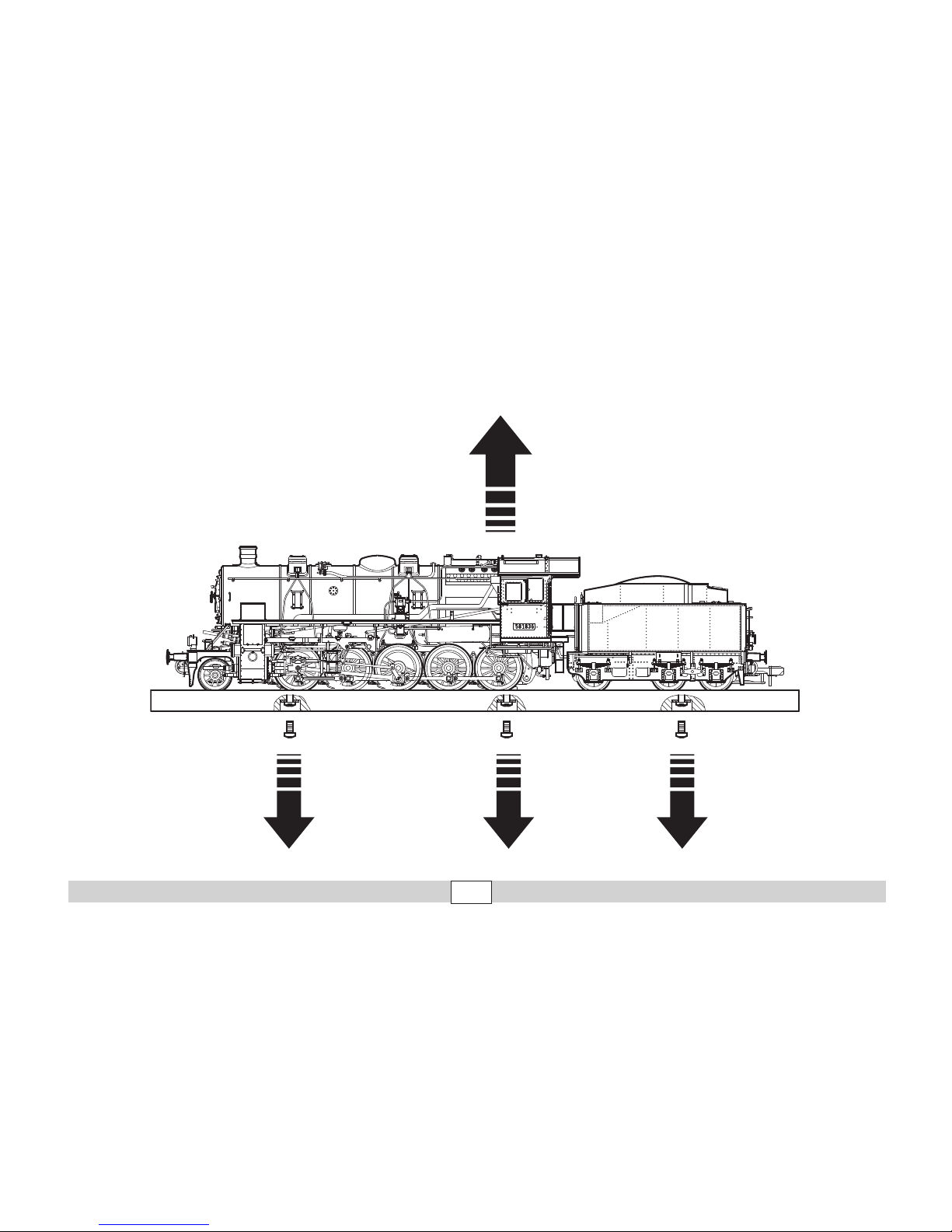
marklin 55581 User manual

Modell der Dampflokomotive BR 58
55581

2
Inhaltsverzeichnis:
Seite
1. Informationen zum Vorbild 3
2. Hinweise zur Inbetriebnahme 4
3. Sicherheitshinweise 6
4. Allgemeine Hinweise 6
5. Funktionen 6
6. Schaltbare Funktionen 7
7. Parameter / Register 8
8. Betriebshinweise 18
9. Ergänzendes Zubehör 20
10. Wartung und Instandhaltung 25
Table of Contents:
Page
1. Information about the prototype 3
2. Notes about using this model for the first time 4
3. Safety Notes 9
4. General Notes 9
5. Functions 9
6. Controllable Functions 10
7. Parameter / Register 11
8. Information about operation 18
9. Complementary accessories 20
10. Service and maintenance 25
Sommaire :
Page
1. Informations concernant la locomotive réelle 3
2. Indications relatives à la mise en service 4
3. Remarques importantes sur la sécurité 12
4. Informations générales 12
5. Fonctionnement 12
6. Fonctions commutables 13
7. Paramètre / Registre 14
8. Remarques sur l’exploitation 18
9. Accessoires complémentaires 20
10. Entretien et maintien 25
Inhoudsopgave:
Pagina
1. Informatie van het voorbeeld 3
2. Opmerking voor de ingebruikname 4
3. Veiligheidsvoorschriften 15
4. Algemene informatie 15
5. Functies 15
6. Schakelbare functies 16
7. Parameter / Register 17
8. Opmerkingen over de werking 18
9. Aanvullende toebehoren 20
10. Onderhoud en handhaving 25

3
1. Informationen zum Vorbild
Mit der G 12 schufen die preußischen Staatsbahnen eine Vorläuferin der
Einheitslokomotiven. Zwar waren schon frühere Konstruktionen auch von
Eisenbahnen anderer Länder beschafft worden. Diesmal aber - man schrieb
das Jahr 1916 - drängte das Militär, den Fahrzeugpark der Länderbahnen zu
vereinheitlichen. 1917 stand die erste Lok auf den Gleisen. Sie verfügte über
ein Dreizylinder-Triebwerk. Damit unterschied sie sich deutlich von älteren
preußischen Konstruktionen. Auch der Barrenrahmen und der breite Hinter-
kessel der Bauart Belpaire entsprachen keineswegs der reinen preußischen
Lehre. Um die geforderte maximale Achsfahrmasse von 16 t zu erreichen, er-
hielt die G 12 ein fünffach gekuppeltes Triebwerk. Die Staatsbahnen Badens,
Preußens, Sachsens und Württembergs stellten die G 12 in Dienst. Insgesamt
entstanden von der Konstruktion etwa 1500 Exemplare. Die letzten Maschinen
fuhren in der DDR bis 1976.
1. Information about the prototype
The Prussian State Railways created a predecessor to the standard design
locomotives with the G 12. It’s true that railroads in other countries had also
purchased earlier designs like this. This time however - in 1916 - there was
military pressure to standardize the motive power of provincial railroads. The
first locomotive was delivered in 1917. It had three-cylinder running gear. This
clearly differentiated it from older Prussian designs. The sectional frame and
the broad Belpaire firebox design were totally different from purely Prussian
designs. The G 12 was equipped with running gear having five coupled wheel
sets in order to achieve the required axle load limit of 16 metric tons. The
Baden, Prussian, Saxon, and Württemberg State Railways placed the G 12 into
service. Approximately 1,500 units were built from this design. The last of these
locomotives were in service in East Germany until 1976.
1. Informations concernant la locomotive réelle
La G 12 des Chemins de fer Prussiens fut une « précurseuse» des locomoti-
ves unifiées. Des compagnies ferroviaires d‘autres Länder avaient certes déjà
acheté des constructions plus anciennes. Cette fois cependant - en 1916 -,
l‘armée poussait à unifier le parc de véhicules des Länderbahn. La première
locomotive fut sur les rails en 1917. Elle disposait d‘un mécanisme moteur à
trois cylindres et se distinguait ainsi sensiblement des constructions prus-
siennes plus anciennes. Le châssis en barres et la large boîte à feu et foyer
du type Belpaire ne correspondaient non plus en rien à la «pure» philosophie
prussienne. Afin d‘atteindre la charge maximale par essieu exigée de 16 t, la
G 12 fut équipée d‘un mécanisme moteur à cinq essieux couplés. La G 12 fut
mise en service par les Chemins de fer de Bade, Prusse, Saxe et Wurtemberg.
Au total, 1500 unités furent construites. Les dernières machines circulèrent en
RDA jusqu‘en 1976.
1. Informatie van het voorbeeld
Met de G 12 schiepen de Pruisische Staatsbahnen een voorloopster van de
eenheidslocomotieven. Weliswaar waren vroegere constructies ook door
spoorwegmaatschappijen in andere landen aangeschaft, maar deze keer -
men schreef het oorlogsjaar 1916 - drong het militaire apparaat aan op een
uniformiteit bij de Länderbahnen. In 1917 stond de eerste G 12 op de rails. Met
haar driecilinderdrijfwerk onderscheidde ze zich duidelijk van voorgaande
Pruisische constructies. Ook het stavenframe en de brede achterketel van het
type Belpaire kwamen geenszins overeen met de “zuivere“ Pruisische leer.
Om de geëiste maximale asdruk van 16 t te bereiken, kreeg de G 12 een vijf-
voudig gekoppeld drijfwerk. De Staatsbahnen in Baden, Pruisen, Saksen en
Württemberg stelden de G 12 in dienst. In totaal ontstonden ongeveer 1500
exemplaren. De laatste machine reden nog tot 1976 in de DDR.

4
2.
1. 1. 1.
2.

5
2.

6
5. Funktionen
Diese Lokomotive mit eingebauter Mehrzug-Elektronik bietet:
•
Die Betriebsart (Mfx, Märklin-Motorola oder DCC) wird automatisch erkannt.
• Einstellbare Adressen: Märklin 01 – 80, DCC 01 - 9999
• Adresse ab Werk: (Märklin) 58 / (DCC) 03
• Mfx-Technologie für Mobile Station / Central Station.
Name ab Werk: BR58
• Veränderbare Anfahrverzögerung (ABV).
• Veränderbare Bremsverzögerung (ABV).
• Veränderbare Höchstgeschwindigkeit.
• Veränderbare Lautstärke der Geräusche.
• Einstellen der Lokparameter (Adresse, Anfahr-/Bremsverzögerung, Höchst-
geschwindigkeit usw.): mit Control Unit und DCC (CV Programmierung),
Mobile Station oder Central Station.
• Eingebaute Geräuschelektronik, nur im Betrieb mit Märklin Digital,
Märklin Systems oder DCC nutzbar.
• Zusätzliche schaltbare Geräusche.
• Das Modell ist für den Betrieb auf Märklin 1-Gleisen entwickelt. Ein Betrieb
auf anderen Gleissystemen geschieht auf eigenes Risiko.
• Befahrbarer Mindestradius: 1.020 mm
• Fahrtrichtungsabhängige Stirnbeleuchtung.
• Im Analogbetrieb stehen nur die Fahr- und Lichtwechselfunktionen zur
Verfügung.
3. Sicherheitshinweise
• Die Lok darf nur mit einem dafür bestimmten Betriebssystem (Gleichstrom
[DC] = max 18V±, Märklin Wechselstrom, Märklin Digital oder Märklin
Systems) eingesetzt werden.
• Nur Schaltnetzteile/Transformatoren verwenden, die Ihrer örtlichen Netz-
spannung entsprechen.
• Die Lok darf nur aus einer Leistungsquelle versorgt werden.
• Beachten Sie unbedingt die Sicherheitshinweise in der Bedienungsanlei-
tung zu Ihrem Betriebssystem.
• Setzen Sie das Modell keiner direkten Sonneneinstrahlung, starken Tempe-
raturschwankungen oder hoher Luftfeuchtigkeit aus.
• ACHTUNG! Funktionsbedingte scharfe Kanten und Spitzen.
• Für den konventionellen Betrieb der Lok muss das Anschlussgleis entstört
werden. Dazu ist das Entstörset 104 770 zu verwenden. Für Digitalbetrieb
darf das Entstörset nicht verwendet werden.
4. Allgemeine Hinweise
• Die Bedienungsanleitung und die Verpackung sind Bestandteil des Produk-
tes und müssen deshalb aufbewahrt sowie bei Weitergabe des Produktes
mitgegeben werden.
• Für Reparaturen oder Ersatzteile wenden Sie sich bitte an Ihren Märklin-
Fachhändler.
• http://www.maerklin.com/en/imprint.html
Jegliche Garantie-, Gewährleistungs- und Schadensersatzansprüche sind ausgeschlos-
sen, wenn in Märklin-Produkten nicht von Märklin freigegebene Fremdteile eingebaut
werden und / oder Märklin-Produkte umgebaut werden und die eingebauten Fremdteile
bzw. der Umbau für sodann aufgetretene Mängel und / oder Schäden ursächlich war.
Die Darlegungs- und Beweislast dafür, dass der Einbau von Fremdteilen oder der Umbau
in bzw. von Märklin-Produkten für aufgetretene Mängel und / oder Schäden nicht
ursächlich war, trägt die für den Ein- und / oder Umbau verantwortliche Person und /
oder Firma bzw. der Kunde.

7
Funktion
Digital/Systems/DCC
Stirnbeleuchtung function / off Funktion f0 Funktion f0
Rauchgenerator f1 Funktion 7 Funktion f1 Funktion f1
Betriebsgeräusch f2 Funktion 3 Funktion f2 Funktion f2
Geräusch: Lokpfeife f3 Funktion 4 Funktion f3 Funktion f3
Telex-Kupplung hinten f4 Funktion 6 Funktion f4 Funktion f4
Feuerbüchsen flackern — Funktion 8 Funktion f5 Funktion f5
Führerstandsbeleuchtung — Funktion 1 Funktion f6 Funktion f6
Geräusch: Rangierpfiff — Funktion 5 Funktion f7 Funktion f7
ABV — Funktion 2 Funktion f8 Funktion f8
Geräusch: Bremsenquietschen aus — — Funktion f9 Funktion f9
Geräusch: Dampf ablassen — — Funktion f10 Funktion f10
Geräusch: Kohle schaufeln — — Funktion f11 Funktion f11
Geräusch: Schüttelrost — — Funktion f12 Funktion f12
Geräusch: Generator — — Funktion f13 Funktion f13
Geräusch: Injektor — — Funktion f14 Funktion f14
Geräusch: Wasserpumpe — — Funktion f15 Funktion f15
STOPmobile station
systems
15
6. Schaltbare Funktionen

8
CV Bedeutung Wert für 6021 Wert DCC
01 Adresse 01 - 80 (55) 1 - 127 (3)
CV 29/Bit5 =0
02 PoM Minimalgeschwindigkeit — 0 - 255 (4)
03 PoM Anfahrverzögerung 01 - 63 0 - 255 (5)
04 PoM Bremsverzögerung 01 - 63 0 - 255 (3)
05 PoM Maximalgeschwindigkeit 01 - 63 0 - 255 (240)
08 Werkreset/Herstellerkennung 08 08 (131)
13 PoM Funktionen F1 - F8 im Analogbetrieb — 0 - 255 (0)
14 PoM Funktionen F9 - F15 und Licht im Analogbetrieb — 0 - 255 (1)
17 Erweiterte Adresse (oberer Teil CV29 Bit 5 =1) — 193 - 255 (192)
18 Erweiterte Adresse (unterer Teil CV29 Bit 5 =1) — 0 - 255 (128)
19 Traktionsadresse — 0 - 255 (0)
21 PoM Funktionen F1 - F8 bei Traktion — 0 - 255 (0)
22 PoM Funktionen F9 - F15 und Licht bei Traktion — 0 - 255 (0)
29
Bit 0: Umpolung Fahrtrichtung
Bit 1: Anzahl Fahrstufen 14 oder 28/128
Bit 2: DCC Betrieb mit Bremsstrecke
Bit 5: Adressumfang 7 Bit / 14 Bit
—
0 / 1 (0)*
0 / 2 (2)*
0 / 4 (4)*
0 / 32 (0)*
63 Lautstärke 01 - 63 (63) 0 - 255 (255)
mfx: Am mfx-Decoder können über die Tasten der Central Station 60213/60214 Änderungen an den Einstellungen vorgenommen werden. Die
Vorgehensweise entnehmen Sie der Hilfe-Datei der Central Station.
( ) Werte = Werkseinstellung
DCC: programmieren auf dem Programmiergleis mittels CV Programmierung, programmieren mit PoM (Program on the Main); dies muss vom Steuergerät
unterstützt werden.
* Die Werte der gewünschten Einstellungen sind zu addieren! Z.B. Anzahl der Fahrstufen 28/128 = 2 + DCC Betrieb mit Bremsstrecke = 4, ergibt Wert = 6
7.

9
5. Functions
This locomotive has a built-in multi-train electronic circuit and offers these
features:
• The mode of operation (mfx, Märklin Motorola, or DCC) is recognized auto-
matically.
• Possible addresses: Märklin 01 – 80, DCC 01 - 9999
• Address set at the factory: (Märklin) 58 / (DCC) 03
• Mfx technology for the Mobile Station / Central Station.
Name set at factory: BR58
• Adjustable acceleration (ABV).
• Adjustable Braking delay (ABV).
• Adjustable maximum speed.
• Volume can be changed for the sound effects.
• Setting locomotive parameters (address, acceleration/braking delay, maxi-
mum speed, etc.): with the Control Unit and DCC (CV programming),
Mobile Station, or the Central Station.
• Built-in sound effects circuit, can only be used in operation Märklin Digital,
Märklin Systems, or DCC.
• Additional sound effects that can be controlled.
• The model is designed for operation on Märklin 1 Gauge track. As the
consumer you assume the risk for operating on other makes of track.
• Minimum radius for operation: 1020 mm / 23,6-7/8“.
• Headlights, changing over with the direction of travel.
• Only the train control functions and headlight changeover feature are avail-
able in analog operation.
3. Safety Notes
• This locomotive is to be used only with an operating system designed for it
(DC power = 18V±, Märklin AC, Märklin Digital, Märklin Systems).
• Use only switched mode power supply units and transformers that are
designed for your local power system.
• This locomotive must never be supplied with power from more than one
transformer.
• Pay close attention to the safety notes in the instructions for your operat-
ing system.
• Do not expose the model to direct sunlight, extreme changes in tempera-
ture, or high humidity.
• WARNING! Sharp edges and points essential for operational and modelling
conditions.
•
The feeder track must be equipped to prevent interference with radio and
television reception, when the locomotive is to be run in conventional opera-
tion. The 104 770 interference suppression set is to be used for this purpose.
The interference suppression set may not be used for digital operation.
4. General Notes
• The operating instructions and the packaging are a component part of the
product and must therefore be kept as well as transferred along with the
product to others.
• Please see your authorized Märklin dealer for repairs or spare parts.
• http://www.maerklin.com/en/imprint.html
No warranty or damage claims shall be accepted in those cases where parts neither
manufactured nor approved by Märklin have been installed in Märklin products or where
Märklin products have been converted in such a way that the non-Märklin parts or the
conversion were causal to the defects and / or damage arising. The burden of presenting
evidence and the burden of proof thereof, that the installation of non-Märklin parts or
the conversion in or of Märklin products was not causal to the defects and / or damage
arising, is borne by the person and / or company responsible for the installation and / or
conversion, or by the customer.

10
Function
Digital/Systems/DCC
Headlights function / off Function f0 Function f0
Smoke generator f1 Function 7 Function f1 Function f1
Sound effect: Operating sounds f2 Function 3 Function f2 Function f2
Sound effect: Locomotive whistle f3 Function 4 Function f3 Function f3
Rear Telex coupler f4 Function 6 Function f4 Function f4
Glow from firebox — Function 8 Function f5 Function f5
Engineer‘s cab lighting — Function 1 Function f6 Function f6
Sound effect: Switching whistle — Function 5 Function f7 Function f7
ABV — Function 2 Function f8 Function f8
Sound effect: Squealing brakes off — — Function f9 Function f9
Sound effect: Blowing off steam — — Function f10 Function f10
Sound effect: Coal being shoveled — — Function f11 Function f11
Sound effect: Rocker grate — — Function f12 Function f12
Sound effect: Generator — — Function f13 Function f13
Sound effect: Injector — — Function f14 Function f14
Sound effect: Water pump — — Function f15 Function f15
STOPmobile station
systems
15
6. Controllable Functions

11
CV Discription 6021 Value DCC Value
01 Adresse 01 - 80 (55) 1 - 127 (3)
CV 29/bit5 =0
02 PoM Minimum Speed — 0 - 255 (4)
03 PoM Acceleration delay 01 - 63 0 - 255 (5)
04 PoM Braking delay 01 - 63 0 - 255 (3)
05 PoM Maximum speed 01 - 63 0 - 255 (240)
08 Factory Reset / Manufacturer Recognition 08 08 (131)
13 PoM Functions F1 - F8 in analog operation — 0 - 255 (0)
14 PoM Functions F9 - F15 and lights in analog operation — 0 - 255 (1)
17 Extended address (upper part CV29 Bit 5 = 1) — 193 - 255 (192)
18 Extended address (lower part CV29 Bit 5 = 1) — 0 - 255 (128)
19 Multiple Unit Address — 0 - 255 (0)
21 PoM Functions F1 - F8 on Multiple Unit — 0 - 255 (0)
22 PoM Functions F9 - F15 and lights on Multiple Unit — 0 - 255 (0)
29
Bit 0: Reversing direction
Bit 1: Number of speed levels 14 or 28/128
Bit 2: DCC operation with braking area
Bit 5: Address length 7 Bit / 14 Bit
—
0 / 1 (0)*
0 / 2 (2)*
0 / 4 (4)*
0 / 32 (0)*
63 Volume 01 - 63 (63) 0 - 255 (255)
mfx: Changes to the settings on the mfx decoder can be done with the buttons on the 60213/60214 Central Station. The procedure can be
found in the help file on the Central Station.
( ) Values = factory settings
DCC: programming on the programming track by means of CV programming, programming with PoM (Program on the Main); this must be supported by the
controller you are using.
* The values for the desired setting must be added! Example: The number of speed levels 28/128 = 2 + DCC operation with a braking route = 4, results in
the value = 6
7.

12
5. Fonctionnement
Cette locomotive possède un équipement électronique pour conduite multi-
train :
• Le mode d’exploitation (Mfx, Märklin-Motorola ou DCC) est identifié auto-
matiquement.
• Adresses pouvant être paramétrées : Märklin 01 – 80, DCC 01 - 9999
• Adresse départ usine : (Märklin) 58 / (DCC) 03
• Technologie Mfx pour Mobile Station / Central Station.
Nom encodee en usine : BR58
• Temporisation d’accélération réglable (ABV).
• Temporisation de freinage réglable (ABV).
• Vitesse maximale réglable.
• Bruitages complémentaires commutables.
• Volume des bruitages réglable.
• Paramétrer les paramètres des locomotives (adresse, retardement au
démarrage / au freinage, vitesse maximale etc.) avec unité de contrôle et
DCC (programmation CV), station mobile ou station centrale.
• Electronique de bruitage intégrée, ne peut être utilisée qu’en étant exploi-
tée avec Märklin Digital, Märklin Systems ou DCC.
• Le modèle réduit est conçu pour rouler sur des voies Märklin 1. Le faire
rouler sur des voies d’autres systèmes comporte des risques.
• Rayon minimal d’inscription en courbe : 1020 mm.
• Feux de signalisation avec inversion selon sens de marche.
• En mode d’exploitation analogique, seules les fonctions relatives à la
conduite et à l‘inversion des feux sont disponibles.
3. Remarques importantes sur la sécurité
• La locomotive ne peut être mise en service qu’avec un système d’exploita-
tion adéquat (DC = 18V ±, Märklin AC, Märklin Digital ou Märklin Systems).
• Utiliser uniquement des convertisseurs et transformateurs correspondant à
la tension du secteur local.
• La locomotive ne peut être alimentée en courant que par une seule source
de courant.
• Veuillez impérativement respecter les remarques sur la sécurité décrites
dans le mode d’emploi de votre système d’exploitation.
• Ne pas exposer le modèle à un ensoleillement direct, à de fortes variations
de température ou à un taux d‘humidité important.
• ATTENTION! Pointes et bords coupants lors du fonctionnement du produit.
• Pour l’exploitation de la locomotive en mode conventionnel, la voie de rac-
cordement doit être déparasitée. A cet effet, utiliser le set de déparasitage
réf. 104 770. N’utilisez en aucun cas le kit d’antiparasitage pour l’exploita-
tion en mode numérique.
4. Indications générales
• La notice d‘utilisation et l’emballage font partie intégrante du produit ; ils
doivent donc être conservés et, le cas échéant, transmis avec le produit.
• Pour toute réparation ou remplacement de pièces, adresses-vous à votre
détaillant-spécialiste Märklin.
• http://www.maerklin.com/en/imprint.html
Tout recours à une garantie commerciale ou contractuelle ou à une demande de
dommages-intérêt est exclu si des pièces non autorisées par Märklin sont intégrées
dans les produits Märklin et / ou si les produits Märklin sont transformés et si les pièces
d’autres fabricants montées ou la transformation constituent la cause des défauts et /
ou dommages apparus. C’est à la personne et / ou la société responsable du montage /
de la transformation ou au client qu’incombe la charge de prouver que le montage des
pièces d’autres fabricants sur des produits Märklin ou la transformation des produits
Märklin n’est pas à l’origine des défauts et ou dommages apparus.

13
6. Fonctions commutables
Fonction
Digital/Systems/DCC
Fanal function / off Fonction f0 Fonction f0
Générateur de fumée f1 Fonction 7 Fonction f1 Fonction f1
Bruitage : Bruit d’exploitation f2 Fonction 3 Fonction f2 Fonction f2
Bruitage : Sifflet locomotive f3 Fonction 4 Fonction f3 Fonction f3
Attelage Telex à l’arrière f4 Fonction 6 Fonction f4 Fonction f4
Lueurs dans le foyer — Fonction 8 Fonction f5 Fonction f5
Eclairage de la cabine de conduite — Fonction 1 Fonction f6 Fonction f6
Bruitage : Sifflet pour manœuvre — Fonction 5 Fonction f7 Fonction f7
ABV — Fonction 2 Fonction f8 Fonction f8
Bruitage : Grincement de freins désactivé — — Fonction f9 Fonction f9
Bruitage : Échappement de la vapeur — — Fonction f10 Fonction f10
Bruitage : Pelletage du charbon — — Fonction f11 Fonction f11
Bruitage : Grille à secousses — — Fonction f12 Fonction f12
Bruitage : Dynamo d‘éclairage — — Fonction f13 Fonction f13
Bruitage : Injecteur — — Fonction f14 Fonction f14
Bruitage : Pompe à eau — — Fonction f15 Fonction f15
STOPmobile station
systems
15

14
CV Affectation 6021 Valeur DCC Valeur
01 Adresse 01 - 80 (55) 1 - 127 (3)
CV 29/Bit5 =0
02 PoM Vitesse min — 0 - 255 (4)
03 PoM Temporisation d‘accélération 01 - 63 0 - 255 (5)
04 PoM Temporisation de freinage 01 - 63 0 - 255 (3)
05 PoM Vitesse maximale 01 - 63 0 - 255 (240)
08 Réinitialisation d’usine/identification du fabricant 08 08 (131)
13 PoM Fonctions F1 - F8 en mode analog — 0 - 255 (0)
14 PoM Fonctions F9 - F15 et éclairage en mode analog — 0 - 255 (1)
17 Adresse étendue (partie supérieure CV29 Bit 5 = 1) — 193 - 255 (192)
18 Adresse étendue (partie inférieure CV29 Bit 5 = 1) — 0 - 255 (128)
19 Adresse traction — 0 - 255 (0)
21 PoM Fonctions F1 - F8 pour traction — 0 - 255 (0)
22 PoM Fonctions F9 - F15 et éclairage traction — 0 - 255 (0)
29
Bit 0: Inv. polarité Sens de marche
Bit 1: Nombre de crans de marche 14 ou 28/128
Bit 2:
Mode DCC avec dist. de freinage
Bit 5: Capacité d’adresses 7 Bit / 14 Bit
—
0 / 1 (0)*
0 / 2 (2)*
0 / 4 (4)*
0 / 32 (0)*
63 Volume 01 - 63 (63) 0 - 255 (255)
mfx : au niveau du décodeur mfx, il est possible de procéder à des modifications des paramétrages par l’intermédiaire des touches de la
station centrale 60213/60214. Vous trouverez les informations sur la manière de procéder dans le fichier d’aide correspondant à la station centrale.
( ) Valeurs = paramétrage départ usine
DCC : programmer sur la voie de programmation au moyen de la programmation CV, programmer avec PoM (Program on the Main) ; ceci doit être supporté
par le dispositif de commande.
* Il convient d’additionner les valeurs des paramétrages souhaités ! P. ex. le nombre des crans de marche 28/128 = 2 + DCC Exploitation avec distance
de freinage = 4, donne la valeur = 6
7.

15
5. Werking
Deze loc met ingebouwde digitaalelektronica biedt u:
• Het bedrijfssysteem (mfx, Märklin-Motorola of DCC) wordt automatisch
herkend.
• Instelbare adressen: Märklin (01- 80), (DCC) 01 - 9999
• Af fabriek ingesteld adres: (Märklin) 58 / (DCC) 03
• Mfx-technologie voor het Mobile Station / Central Station.
Naam af de fabriek: BR 58
• Instelbare optrekvertraging.
• Instelbare afremvertraging.
• Instelbare maximumsnelheid.
• Volume van de geluiden instelbaar.
• Instellen van de loc-parameters (adres, optrek-/afremvertraging, maxi-
mumsnelheid enz.) met Control Unit en DCC (CV programmering),
Mobile Station of Central Station.
• Ingebouwde geluidselektronica, alleen te gebruiken met Märklin digitaal,
Märklin systems of DCC.
• Extra schakelbare geluiden.
• Het model is ontwikkeld voor het gebruik op het Märklin Spoor 1 railsys-
teem. Het gebruik op een ander railsysteem geschied op eigen risico.
• Berijdbare minimumradius: 1020 mm.
• Rijrichtingafhankelijke frontseinen.
• In analoogbedrijf zijn alleen de rij- en lichtwissel-functies beschikbaar.
3. Veiligheidsvoorschriften
•
De loc mag alleen met een daarvoor bestemd bedrijfssysteem (DC =18V ±,
Märklin AC, Märklin digitaal of Märklin Systems) gebruikt worden.
• Alleen net-adapters en transformatoren gebruiken waarvan de aangege-
ven netspanning overeenkomt met de netspanning ter plaatse.
• De loc mag niet vanuit meer dan één stroomvoorziening gelijktijdig gevo-
ed worden.
• Lees ook aandachtig de veiligheidsvoorschriften in de gebruiksaanwij-
zing van uw bedrijfssysteem.
• Stel het model niet bloot aan in directe zonnestraling, sterke temperatu-
urwisselingen of hoge luchtvochtigheid.
• OPGEPAST! Functionele scherpe kanten en punten.
• Voor het conventionele bedrijf met de loc dient de aansluitrail te worden
ontstoort. Hiervoor dient men de ontstoor-set 104 770 te gebruiken. Voor
het digitale bedrijf is deze ontstoor-set niet geschikt. Bij het digitale
bedrijf mag de ontstoringsset niet worden gebruikt.
4. Algemene informatie
• De gebruiksaanwijzing en de verpakking zijn een bestanddeel van het
product en dienen derhalve bewaard en meegeleverd te worden bij het
doorgeven van het product.
•
Voor reparatie of onderdelen kunt u zich tot uw Märklin handelaar wenden.
• http://www.maerklin.com/en/imprint.html
Elke aanspraak op garantie en schadevergoeding is uitgesloten, wanneer in Märklin-produc-
ten niet door Märklin vrijgegeven vreemde onderdelen ingebouwd en / of Märklin-producten
omgebouwd worden en de ingebouwde vreemde onderdelen resp. de ombouw oorzaak
van nadien opgetreden defecten en / of schade was. De aantoonplicht en de bewijslijst
daaromtrent, dat de inbouw van vreemde onderdelen in Märklin-producten of de ombouw
van Märklin-producten niet de oorzaak van opgetreden defecten en / of schade is geweest,
berust bij de voor de inbouw en/of ombouw verantwoordelijke persoon en / of firma danwel
bij de klant.

16
Functie
Digital/Systems/DCC
Frontverlichting function / off Functie f0 Functie f0
Rookgenerator f1 Functie 7 Functie f1 Functie f1
Geluid: bedrijfsgeluiden f2 Functie 3 Functie f2 Functie f2
Geluid: locfluit f3 Functie 4 Functie f3 Functie f3
Telex-koppeling achter f4 Functie 6 Functie f4 Functie f4
Brandende fuur — Functie 8 Functie f5 Functie f5
Cabineverlichting — Functie 1 Functie f6 Functie f6
Geluid: rangeerfluit — Functie 5 Functie f7 Functie f7
ABV — Functie 2 Functie f8 Functie f8
Geluid: piepende remmen uit — — Functie f9 Functie f9
Geluid: stoom afblazen — — Functie f10 Functie f10
Geluid: kolenscheppen — — Functie f11 Functie f11
Geluid: schudrooster — — Functie f12 Functie f12
Geluid: generator — — Functie f13 Functie f13
Geluid: injector — — Functie f14 Functie f14
Geluid: waterpomp — — Functie f15 Functie f15
STOPmobile station
systems
15
6. Schakelbare functies

17
CV Betekenis Waarde 6021 Waarde DCC
01 Adres 01 - 80 (55) 1 - 127 (3)
CV 29/Bit5 =0
02 PoM minimale snelheid — 0 - 255 (4)
03 PoM Optrekvertraging 01 - 63 0 - 255 (5)
04 PoM Afremvertraging 01 - 63 0 - 255 (3)
05 PoM Maximumsnelheid 01 - 63 0 - 255 (240)
08 Fabrieksinstelling/fabriekherkenning 08 08 (131)
13 PoM functies F1 - F8 in analoogbedrijf — 0 - 255 (0)
14 PoM functies F9 - F15 en licht in analoogbedrijf — 0 - 255 (1)
17 Uitgebreld adres (bovenste gedeelte CV29 Bit 5 = 1) — 193 - 255 (192)
18 Uitgebreld adres (onderste gedeelte CV29 Bit 5 = 1) — 0 - 255 (128)
19 tractieadres — 0 - 255 (0)
21 PoM functies F1 - F8 in tractie — 0 - 255 (0)
22 PoM functies F9 - F15 en licht in tractie — 0 - 255 (0)
29
Bit 0: ompolen rijrichting
Bit 1: aantal rijstappen 14 of 28/128
Bit 2: DCC bedrijf met afremtraject
Bit 5: adresomvang 7 Bit / 14 Bit
—
0 / 1 (0)*
0 / 2 (2)*
0 / 4 (4)*
0 / 32 (0)*
63 Volume 01 - 63 (63) 0 - 255 (255)
mfx: de instellingen van mfx decoders kunnen via de toetsen van het Central Station 60213/60214 gewijzigd worden. De werkwijze vindt u in het
hulpbestand van het Central Station.
( ) waarde = fabrieksinstelling
DCC: programmeren op het programmeerspoor door middel van CV programmering, programmeren met PoM (Program on the Main); dit dient door het
besturingsapparaat ondersteund te worden.
* De waarden van de gewenste instellingen dienen bij elkaar opgeteld te worden! Bijv. aantal rijstappen 28/128 = 2 + DCC bedrijf met afremtraject = 4,
geeft een waarde van 2+4=6.
7.

18
8.
Anschluss der Gleisanlage
Um Spannungsverluste auf der
Anlage zu vermeiden, ist immer auf
gutes Zusammenpassen der Schie-
nenverbindungslaschen zu achten.
Alle 2 bis 3 m ist eine neue Strom-
einspeisung über die Anschluss-
klemmen 5654 empfehlenswert.
Befahren von Steigungen
Im Gegensatz zum Vorbild können
mit einer Modellbahn auch größere
Steigungen befahren werden. Im
Normalfall sollte eine Steigung
bei maximal 3 Prozent liegen. Im
Extremfall sind bei entsprechend
eingeschränkter Zugleistung maxi-
mal 5 Prozent möglich. Der Anfang
und das Ende der Steigung sind auf
jeden Fall auszurunden.
Der Unterschied in der Steigung,
zwischen zwei mindestens 300 mm
langen Gleisstücken, darf maximal
1 bis 1,5 Prozent betragen.
8.
Connections between the track
layout and the transformer
Rail joiners must fit well on the rails
of the track to which they are joined
to avoid voltage drop on the layout.
We recommend that you install fee-
der wires every 2 to 3 meters (7 to 10
feet) using the 5654 feeder clips.
Operating the locomotive on grades
In contrast to the prototype
a
locomotive on a model railroad
can operate up steeper grades.
As a general rule a grade should
be no steeper than 3%. In extreme
situations a maximum grade of 5%
is permissible, keeping in mind that
the locomotive’s tractive effort will
be less. The beginning and the end
of the grade must always work
gradually up to maximum grade for
the route.
The maximum allowable difference
in grade between two track sec-
tions, each with a minimum length of
300 mm (11-3/4“) is 1 to 1.5 percent.
8.
Connexion des voies ferrées
Pour éviter des pertes de potentiel
sur l’installation, il faut veiller à
ce que les éclisses de liaison des
rails soient toujours parfaitement
adaptées. Une nouvelle alimenta-
tion électrique est conseillée tous
les 2 à 3 m au moyen des griffes
d’alimentation 5654.
Franchissement des côtes
Contrairement à l’original, la ma-
quette est également en mesure de
franchir des côtes assez impor-
tantes. En temps normal, une côte
devrait étre de l’ordre de 3% ma-
ximum. A l’extrême limite, 5% sont
envisageables avec une puissance
du train réduite en consequence. Le
début et la fin de la côte doivent en
tous cas étre arrondis.
La différence de pente entre deux
éléments de voie d’au moins 300 mm
de longueur doit étre de 1 à 1,5%
maximum.
8.
Aansluiting van de sporen
Om spanningsverlies op de
modelbaan te voorkomen moeten
de raillassen altijd goed op elkaar
aansluiten. Om de 2 à 3 meter moet
de voeding opnieuw op de rails
gezet worden. Daarbij zijn de aans-
luitklemmen 5654 aan te raden.
Berijden van hellingen
In tegenstelling tot het grote voorbe-
eld kunnen met een modelbaan ook
grotere hellingen bereden worden.
Normaal moet een helling maximaal
3 procent zijn.
In extreme gevallen is
maximaal 5 procent mogelijk, maar
dan moet rekening gehouden wor-
den met een evenredig verlies aan
vermogen. Het begin en het einde
van de helling moeten altijd gerond
worden.
Het verschil in de helling tussen
twee tenminste 300 mm lange
railstukken mag maximaal 1 à 1,5
procent bedragen.

19
1.
Fahren
Operating Locomotives
Conduite
Rijden
Programmieren (Lokomotive)
Programming (programming the
locomotive)
programmer (programmer la loco-
motive)
programmeren (locomotief program-
meren)
8.

20
8.
Märklin
02420
Table of contents
Languages:
Other marklin Toy manuals

marklin
marklin 7686 User manual

marklin
marklin My World 29301 User manual

marklin
marklin 74923 User manual

marklin
marklin DE 6/6 User manual

marklin
marklin 37867 User manual

marklin
marklin Oberleitung User manual

marklin
marklin 39501 User manual

marklin
marklin 49965 User manual

marklin
marklin REIHE 1016 User manual

marklin
marklin Ce 6/8 III Krokodil Series User manual

marklin
marklin 29043 User manual

marklin
marklin 36863 User manual

marklin
marklin 37399 User manual

marklin
marklin 36621 User manual

marklin
marklin 37568 User manual

marklin
marklin 39189 User manual

marklin
marklin 59934 User manual

marklin
marklin 39011 User manual

marklin
marklin BR 218 User manual

marklin
marklin 37927 User manual