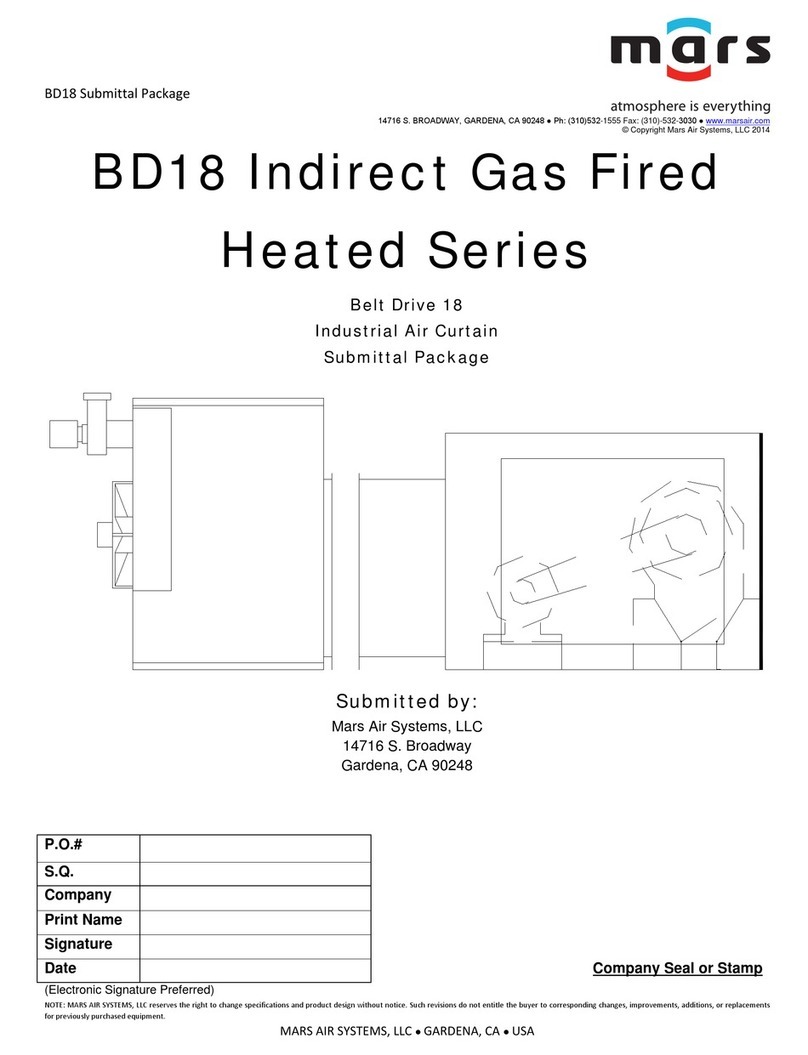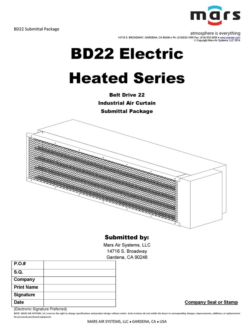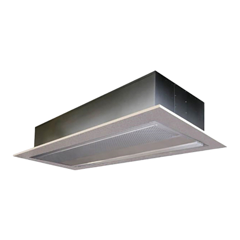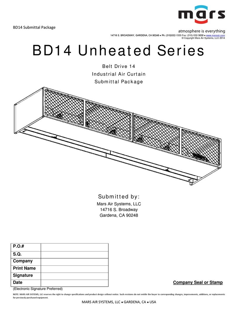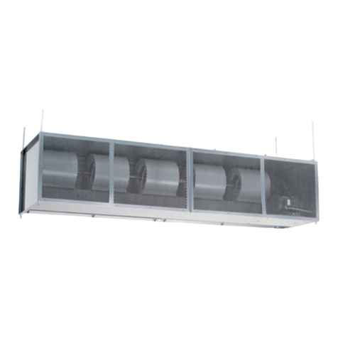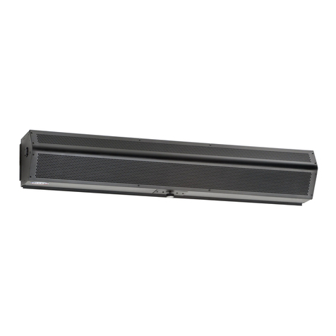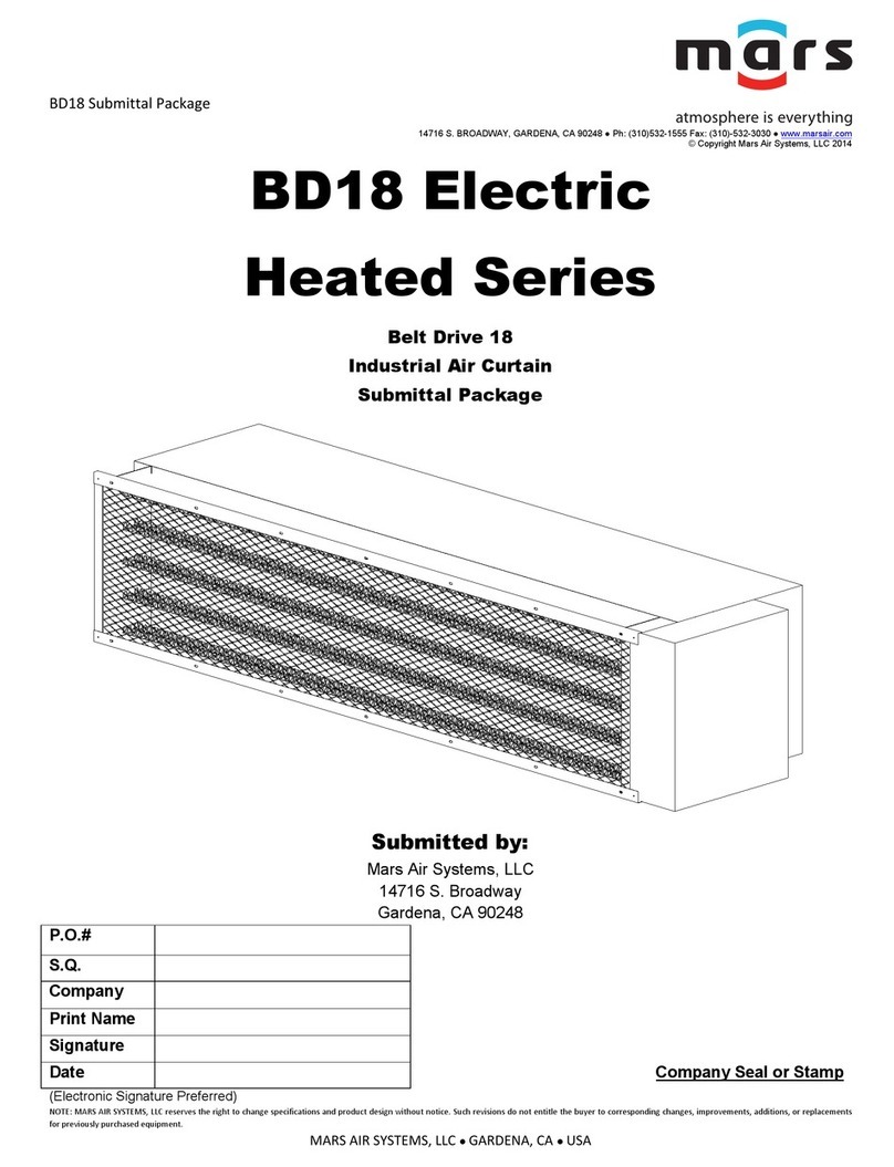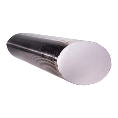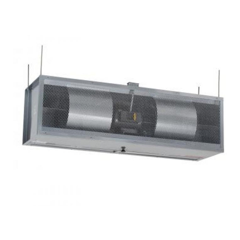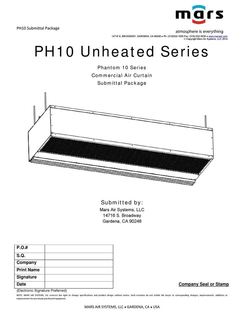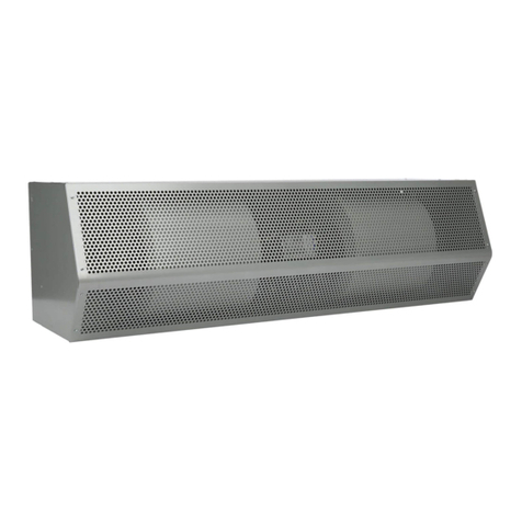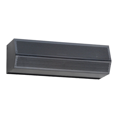
BD18 (Belt Drive 18) Series
Indirect Gas Fired
Model Lengths 96” – 192”
14716 S. BROADWAY, GARDENA, CA 90248 ● Ph: (310) 532-1555 Fax: (310) 532-3030 ● www.marsair.com
© Copyright Mars Air Systems, LLC 2014
NOTE: MARS AIR SYSTEMS, LLC reserves the right to change specifications and product design without notice. Such revisions do not entitle the buyer to corresponding changes, improvements, additions, or replacements
for previously purchased equipment.
MARS AIR SYSTEMS, LLC ● GARDENA, CA ● USA AR, 8/3/21
BD18
Series: BELT DRIVE 18
144 1 I H TS
LENGTH OF UNIT
# OF MOTORS
VOLTAGE CODE
COLOR
EXAMPLE
BD1896-1I*-TS 2250 415 28 5" Rnd 1/2"
BD18120-1I*-TS 2400 664 36 6" Rnd 3/4"
BD18144-1I*-TS 2400 664 30 6" Rnd 3/4"
BD18168-1I*-TS 3400 996 38 6" Rnd 3/4"
BD18192-1I*-TS 3400 996 33 6" Rnd 3/4"
* - Use corresponding letters in"Electrical Data" columns to complete the model numbers.
Note: Gas pressure required min/max in (“wc)(kPa): Natural Gas (3.5/14)(0.9/3.5) and LP (10/14)(2.5/3.5)
Indirect Gas Fired Data Sheet
Applications: Environmental Separation: Max Height 20’ / Insect Control: Max Height 18’
Features:
Air Curtain and Transition
7 ½ to 15 HP continuous duty premium efficiency industrial TEFC
motors
Air curtain is a self-contained one-piece heavy gauge corrosion proof
paint lock metal design
Top mounting holes provided (3/4”)
Cabinet has sufficient strength for fastening from overhead on both
ends without intermediate support
Adjustable air directional nozzle with 40° sweep front to back
Transition is shipped fully assembled and fastened to unit (overhead
support required)
Standard color is Titanium Silver
Rust preventative electrostatic polyurethane powder coating
12-month parts warranty
Freight Not Included (FOB Factory)
Proudly Made in the USA
Indirect Gas Fired Furnaces
ETL verified to be 83% efficient
In-shot burner technology
Aluminized tubular heat exchanger (20 gauge)
Positive pressure 120V impellers (separate 120V, 1Ø power required)
Power vented exhaust
Single stage gas valve
Standard direct spark ignition
Certified for Category I and III Venting
Natural gas
Factory test fired
Overhead mounting hardware provided (2 per furnace)
Mars Recommended Accessories (see submittals for additional details):
Door limit switches
o99-125, Industrial surface-mounted door limit switch
Controllers
oMCP*-†I‡, Motor Control Panel, 24V control voltage (* = HP Code, † = # of Motors, ‡ = Voltage Code)
Note: possible HP Codes = G (7½ HP), H (10 HP), I (15 HP)
MCP-TD, Adjustable time delay, 1sec-100hr (panel required)
IDF-2STG, Two-stage heat exchanger
IDF-SS, 409 stainless steel heat exchanger
IDF-MOD-RS, Room sensor for modulating gas valves (0-10VDC/4-20mA control voltage by others)
Sound Levels: (measured at 10’ in an open field)
7 ½ HP Motor Unit = 74 dBA, 10 HP Motor Unit = 75 dBA, 15 HP Motor Unit = 76 dBA
Length
(in)
Depth
(in)
Height
(in)
Motor
(hp)
BD1896-1I*-TS
96 107 82 1/2 33 7 1/2 1148 2 @ 211 5100 13800
BD18120-1I*-TS
120 131 82 1/2 33 7 1/2 1513 2 @ 335 5100 17255
BD18144-1I*-TS
144 155 82 1/2 33 10 1630 2 @ 335 5100 20700
BD18168-1I*-TS
168 179 82 1/2 33 10 2082 3 @ 335 5100 24100
BD18192-1I*-TS
192 203 82 1/2 33 15 2199 3 @ 335 5100 27600
* - Use corresponding letters in "Electrical Data" columns to complete the model numbers. Note: Data above is for 60 Hz, 17% reduction in the performance data with 50 Hz.
** - Total Weight includes air curtain, transition, and furnace weights.
208/230v
(G)
460v
(H)
575v
(I) 115V
BD1896-1I*-TS
21.6/20.0 10.0 8.9 16.0
BD18120-1I*-TS
21.6/20.0 10.0 8.9 27.0
BD18144-1I*-TS
28.0/26.0 13.0 10.3 27.0
BD18168-1I*-TS
28.0/26.0 13.0 10.3 40.5
BD18192-1I*-TS
42.0/40.0 20.0 15.6 40.5
* - Use corresponding letters in"Electrical Data" columns to complete the model numbers.
Alternate voltage codes with FLA (Full Load Amp) data:
380-415V/3Ø/50Hz (W) - 8.3A per motor (7½HP), 11.5A per motor (10HP), 15.5A per motor (15HP)
Note: For ampacity, multiply FLA X 1.25
Unit Voltage
(Voltage Code)
