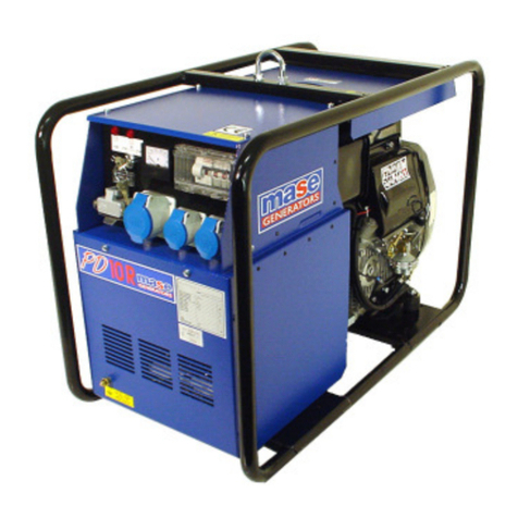
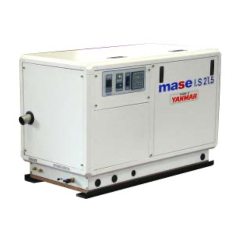
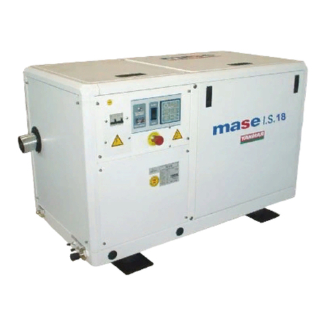
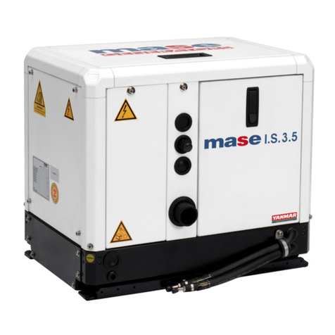
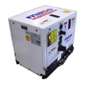
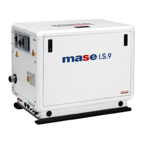
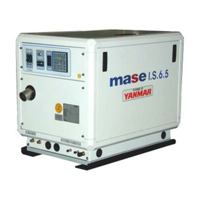
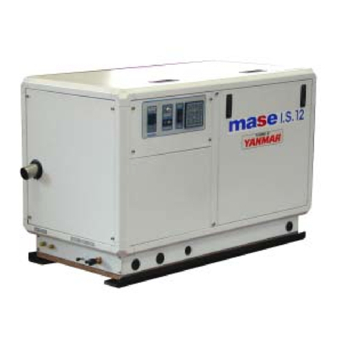
Mase IS 2500 User manual

IS 2500
IS 3500
IS 4500
IS 5500
cod. 41099
MANUALE D'INSTALLAZIONE
INSTALLATION MANUAL
MANUEL D'INSTALLATION
INSTALLATIEHANDLEIDING
masemase
masemase
mase
GENERATORS

GENERATORS IS 2500 - 3500 - 4500 - 5500
- 2 -
12
Fig. 1
Fig. 2
Fig. 3
IS 4500 730 425 500 148 405 176

- 3-
IS 2500 - 3500 - 4500 - 5500 GENERATORS
IMPORTANT
A-Tubes, internal diameter 45 mm
B-Tubes, internal diameter 15 mm
C-Clamps
CAUTION
The measurements shown in fig. 4 should
correspondexactly.
IMPORTANT.
A-Tuyauterie d'un diamètre interne de 45 mm.
B-TuyauterieencaoutchoucNèoprèned'undiamètre
interne de 15 mm.
C-Bagues de serrage.
ATTENTION
Il est très important de respecter les dimensions
indiquèes sur les figures 4
IMPORTANTE
A-Tubazionediam. 45 mm.interno.
B-Tubazione in neoprene diam. 15 mm interno.
C-Fascette di serraggio.
ATTENZIONE
E' molto importante rispettare le misure
riportate in fig. 4
BELANGRIJK
A - Slangen,inwendige diameter 45mm.
B - Slangen,inwendige diameter 15mm.
C - Slangenklemmen
LETOP
Maten zoals aangegeven in fig. 4 dienen
aangehoudente worden.
1Presa a mare
2Rubinetto genera acqua
3Rubinetto svuotamento impianto
4Filtro acqua
5Gruppo elettrogeno
6Marmitta
7Silenziatore
8Bocchettone scarico a mare
9Linea di galleggiamento
Sea intake Prise en mer
General tap-water Robinet gènèral de l’eau
Tap to drain system Robinet de vidage de l’installation
Water filter Filtrè à eau
Electric generator Groupe èletrogène
Mmuffler Pot
Silencer Silencieux
Sea drainage nozzle Goult dècharge en mer
Water line Ligne de flottaison
Huiddoorvoer
Huidafsluiter
Aftapkraan
Wierpot
Generator
Waterslot
Demper
Huiddoorvoer
Waterlijn
Fig. 4

GENERATORS IS 2500 - 3500 - 4500 - 5500
- 4 -
Fig. 5
1Presa a mare
2Rubinetto genera impianto
3Rubinetto svuotamento impianto
4Filtro acqua
5Vanvola antisifone
6Marmitta
7Silenziatore
8Bocchettone scarico a mare
9Linea di galleggiamento
10 Drenaggio
11 Miscelatore di scarico
12 Pompa acqua
13 Gruppo elettrogeno
Sea intake Prise en mer
General tap-systemr Robinet gènèral de l’eau
Tap to drain system Robinet de vidage de l’installation
Water filter Filtrè à eau
Anti-siphon valve Soupape antisiphon
Muffler Pot
Silencer Silencieux
Sea drainage nozzle Goult dècharge en mer
Water line Ligne de flottaison
Drainage Drainage
Drain mixer Mèlangeur de purge
Water pump Pompe à eau
Electric generator Goupe èletrogène
Huidafsluiter
Aftapkraan
Waterfilter
Beluchter
Waterslot
Demper
Huiddoorvoer
Waterlijn
Lekleiding
Waterinjectiebocht
Waterpomp
Generator
IMPORTANT
A-Tubes, internal diameter 45 mm
B-Tubes, internal diameter 15 mm
C-Clamps
CAUTION
The measurements shown in fig. 5 should
correspondexactly.
IMPORTANTE
A-Tubazionediam. 45 mm.interno.
B-Tubazione in neoprene diam. 15 mm interno.
C-Fascette di serraggio.
ATTENZIONE
E' molto importante rispettare le misure
riportate in fig. 5
IMPORTANT.
A-Tuyauterie d'un diamètre interne de 45 mm.
B-TuyauterieencaoutchoucNèoprèned'undiamètre
interne de 15 mm.
C-Bagues de serrage.
ATTENTION
Il est très important de respecter les dimensions
indiquèes sur les figures 5.
BELANGRIJK
A - Slangen, inwendigediameter 45 mm.
B - Slangen, inwendigediameter 15 mm.
C - Slangenklemmen
LETOP
Maten zoals aangegeven in fig. 5 dienen
aangehoudente worden.

- 5-
IS 2500 - 3500 - 4500 - 5500 GENERATORS
1
Fig. 6
Fig. 7
Fig. 8
Fig. 9
Pompa acqua
Waterpump
Pompe à l'eau
Waterpomp
1
2
1Ritorno gasolio •Diesel return • Retourn du gasoil
2Gasolio • Diesel • Gasoil Fig. 10
Miscelatore di scarico
Drain mixer
Mèlangeur de purge
Waterinjectiebocht
VALVOLA ANTISIFONE
ANTI-SIPHON VALVE
SOUPAPE ANTISIPHON
BELUCHTER
Valvola antisifone
Anti-siphon valve
Soupape antisiphon
Beluchter

GENERATORS IS 2500 - 3500 - 4500 - 5500
- 6 -
3
1
2
Fig. 11
IS 2500 - 35000
1
1
3
4
5
2
Fig. 14
Fig. 15
Fig. 12
9X 0,35 mm
1MARRONE BROWN MARRON BRUIN
2BIANCO WHITE BLANC WIT
3BLUE BLUE BLUE BLAUW
4GRIGIO GREY GRIS GRIJS
5VERDE GREEN VERT GROEN
6ROSA PINK ROSE ROZE
7GIALLO YELLOW JAUNE GEEL
8NERO BLACK NOIR ZWART
9ROSSO RED ROUGE ROOD
CALZA EARTH CONDUCT. AFSCHERMINGS-
METALLICA BRAID MATALLIQUE KABE
L
ALLACCIAMENTO CRUSCOTTO / C. PANEL CONNECTION
BRANCHEMENT / AANSLUITINGEN BEDIENINGSPANEEL
NUMERAZIONE
SCHEDA COMANDI
PRINTED CIRCUIT
NUMBERING
NUMERATION
CARTE COMMANDES
PRINTPLAAT
AANSULUITINGEN
COULERCOLOUR
COLORE
Fig. 13
KLEUR
IS 4500/IS 5500

- 7-
IS 2500 - 3500 - 4500 - 5500 GENERATORS
Fig. 17
Fig. 16
Fig. 18
Fig. 19
Fig. 20
CARICO
LOAD
CHARGE
BELASTING
RETE
MAINS
RESEAU
WALAANSLUTING
CARICO
LOAD
CHARGE
BELASTING
CARICO
LOAD
CHARGE
BELASTING

GENERATORS IS 2500 - 3500 - 4500 - 5500
- 8 -
1.1 Caratteristichedelvano .................................... 9
1.2 Ancoraggiodelgruppo...................................... 9
1.3 Ventilazione..................................................... 9
2.1. Sistemidi adduzionedell'acqua di mare............ 9
2.2 Tipicainstallazionecongruppoelettrogeno
sopralalineadigalleggiamento........................ 9
2.3. Tipicainstallazionecongruppoelettrogeno
sotto la linea di galleggiamento......................... 9
2.4. Componenti ....................................................10
2.5. Sistema di scarico ..........................................10
3.0 Circuitocombustibile.......................................10
4.1. Allacciamentobatteria.....................................11
4.2. Allacciamentocruscottocomandi ....................11
4.3. Allacciamento c.a. ..........................................11
4.4. Commutazionegeneratore-rete......................12
INDICE
I
ILMANCATORISPETTO DELLE SPECIFICHE
CONTENUTE NEL SEGUENTE MANUALE DI
INSTALLAZIONE,COMPORTAILDECADIMENTO
DELLAGARANZIA SUL PRODOTTO
INSTALLAZIONE1
2CIRCUITO ACQUA DI RAFFREDAMENTO
3CIRCUITOCOMBUSTIBILE
COLLEGAMENTOELETTRICI4

- 9-
IS 2500 - 3500 - 4500 - 5500 GENERATORS
1.0. INSTALLAZIONE
1.1. Caratteristiche del vano
Ilgeneratoredeveessereinstallatoinunlocalesufficien-
temente aerato, in grado di assicurare la poca quantità
d'aria necessaria alla combustione del motore.
Illocaledeveessereseparatoedisolatoacusticamente
dalleareeabitabili.
Il generatore va posizionato in modo da facilitare le
normalioperazionidimanutenzione.
E' consigliabile l'installazione nel locale dei motori di
propulsionea pattochequestosiaconformealle condi-
zionisopracitate.
1.2. Ancoraggiodel gruppo
Per il fissaggio del gruppo, predisporre un basamento
per sopportare peso e vibrazioni.
Procedere alla foratura del basamento seguendo le
indicazionidifig.1
1.3. Ventilazione
Ilgeneratoreèdotatodiunsistemainternodiraffredda-
mento forzato attraverso uno scambiatore acqua/aria.
La quantità di aria necessaria alla combustione viene
aspirata tramite l'apertura posta sul basamento (fig. 2):
assicurarsi quindi che questa apertura sia sempre ben
libera.
2.0. CIRCUITO ACQUA DI RAFFREDDAMENTO
Nei gruppi elettrogeni descritti in questo manuale, il
motorevieneraffreddatodaunsistemaacircuitoaperto
nel quale circola acqua di mare.
Laportatadelcircuitoacquamareè di 900 l/h (IS 2500)
e 1200 l/h (IS 3500/IS 4500/IS 5500).
All'atto dell'installazione è necessario predisporre un
circuitodiadduzionedell'acquadimareperilraffredda-
mento e un sistema di scarico per la miscela di gas di
combustione ed acqua.
2.1. Sistema di adduzione dell'acqua di mare
Sulle imbarcazioni i sistemi normalmente adottati per
l'immissione dell'acqua sono due (fig. 3).
1-Sistema a presa diretta
2-Sistemacon deflettore
La MASE raccomanda il sistema a presa diretta rif. 1
fig. 3 in quanto questo sistema previene l'ingresso di
acquainpressioneneicondottidiaspirazione,generan-
do invece una depressione facilmente superabile dalla
prevalenza della pompa acqua del gruppo elettrogeno.
IMPORTANTE
Non applicare nessun tipo di cuffia di
protezione al sistema a presa diretta.
IL SISTEMA A PRESA DIRETTA FORNITO DALLA
DITTAMASE E'STATO MODIFICATO PEREVITARE
A CORPI SOLIDI DI PENETRARE NELL'IMPIANTO
INTASANDOLO. L'UTILIZZO DI ALTRI MATERIALI IN
COMMERCIO COMPORTA UN'ATTENZIONE MAG-
GIORE E UNA PULIZIA PIU' FREQUENTE.
Il sistema con deflettore può invece causare i seguenti
inconvenienti:
a-Sevienemontato conleasolerivolteversolaprua.
Inquestocasodurantela navigazioneecongruppo
elettrogeno spento si crea una pressione nel con-
dottoimmissioneacqua, che può causare il riempi-
mentodell'impianto,finoalraggiungimentodelleluci
di scarico rendendo così possibile l'ingresso di
acquaneicilindri.
b-Sevienemontatoconleasolerivolteversolapoppa.
Inquestocaso durante la navigazione sipuòcreare
una depressione nel condotto immissione acqua,
tale da impedire alla pompa acqua di innescare
l'impianto di raffreddamento o tale da limitare la
portataconconseguentesurriscaldamentodelgrup-
poelettrogeno.
I
2.2. Tipica installazione con gruppo elettrogeno
sopra la linea di galleggiamento :
vedi fig. 4
2.3. Tipica installazione con gruppo elettrogeno
sotto la linea di galleggiamento :
vedi fig. 5

GENERATORS IS 2500 - 3500 - 4500 - 5500
- 10 -
2.4. Componenti
1-Presa a mare del tipo diretto 1/2".
IMPORTANTE
Nel caso il gruppo venga installato ad un altezza
superiore ad 1 Mt. sopra la linea di galleggia-
mento, è necessario montare una valvola di non
ritorno dopo la presa a mare (fig. 6 rif. 1) che
impedisce lo svuotamento del circuito acqua a
motore spento. In caso di svuotamento, durante
l'avviamento si può danneggiare la girante della
pompa acqua; per lo stesso motivo all'atto del
primo avviamento del gruppo è necessario prov-
vedere al riempimento manuale del tubo di aspira-
zione dalla valvola alla pompa.
2-Rubinetto a sfera (Generale impianto) 1/2".
3-Rubinetto a sfera (Spurgo impianto) 1/2".
Serve a vuotare l'impianto di raffreddamento del
gruppoelettrogenopermanutenzionigenerali oper
periodidilungainattività.
4-Filtroacqua(ispezionabile).
Deveproteggereefficacementeilcircuitodiraffred-
damento dall'ingresso di fango, sabbia e alghe.
IMPORTANTE
La rete filtrante dovrà essere del tipo fine.
Si consiglia il tipo con passo 2 - 470 micron,
misure diverse non consentirebbero un buon
rendimento del filtro.
5-Valvolaantisifone:èunavalvolacheriportaapres-
sione atmosferica il circuito di raffreddamento a
motorespento,evitandoilfenomenodi sifonaggio.
Vaobbligatoriamenteusataquandoilgenerato-
re è installato col miscelatore di scarico sulla o
sottolalineadigalleggiamento,evaposizionato
adalmeno50cm.sopraillivellodelmare.(vedifig.
8/9).
IMPORTANTE
Il condotto di drenaggio della valvola antisifone
deve obbligatoriamente viaggiare al di sotto della
stessa impedendo così accumuli di acqua nel
condotto, che deve rimanere sempre vuoto, per
permettere il passaggio di aria nello stesso al
momento dello spegnimento del gruppo
( vedi fig. 7).
N.B.: Si consiglia di portare il condotto di drenaggio in sentina
perchè dallo stesso, durante il normale funzionamento, potreb-
bero fuoriuscire piccole quantità di acqua.
La cassa è già predisposta con n° 2 fori per l'allacciamento della
valvola antisifone (fig. 9).
I
2.5. Sistema di scarico
Il sistema di scarico gas di combustione/acqua del
generatore deve essere indipendente da quello dei
motoriprincipali.
IMPORTANTE
La lunghezza del tubo dal punto più alto del
condotto di scarico alla marmitta non deve supe-
rare mt. 2. Questo per evitare che allo spegnimen-
to del gruppo l'acqua rimasta nel condotto di
scarico possa rifluire al motore dopo aver riempi-
to la marmitta a barilotto.
1-Marmittaa barilotto (capacità3.5litri).
Attenua la rumorosità dello scarico ed impedisce il
riflusso dell'acqua verso il motore. Si consiglia di
installare la marmitta a non più di 1 mt. dal genera-
toreediposizionarlaadunaaltezzaugualeoinferio-
re a quella del basamento del generatore.
2-Silenziatore.
Riduce ulteriormente la rumorosità. Si consiglia di
installarloadunadistanzanonsuperioread1mt.dal
bocchettone di scarico a mare.
3-Bocchettone di scarico a mare.
Va installato in posizione tale da essere sempre
soprail livello delmare.
3.0 CIRCUITOCOMBUSTIBILE
L'alimentazione del gruppo è a gasolio, ed avviene
tramite i raccordi contrassegnati dalle diciture "GASO-
LIO"e"RITORNO GASOLIO"(fig.10,rif.1-2);quest'ul-
timoserveperilritornodelcombustibileineccesso.Nel
collegamento al serbatoio combustibile è necessa-
rio inserire un filtro combustibile; è inoltre buona
normainserireunrubinettosullalineadialimentazionea
valledelserbatoio,edunavalvolaunidirezionale(dinon
ritornosoloperdislivellisuperioria50cm)ondeevitare
losvuotamentodell'impiantocombustibileperqualsiasi
causa. Utilizzare una valvola con apertura 50 millibar.
Itubidelcombustibiledevonoessereingommaresisten-
te agli idrocarburi, di diametro interno 6 mm.
IMPORTANTE
Il gruppo è munito di spurgo nafta automatico.
Qualora fosse necessario lo spurgo manuale
premere il pulsante "ON" sul pannello comandi ed
attendere 30 secondi prima di avviare il gruppo.
IMPORTANTE
Il filtro combustibile deve essere del tipo a cartuc-
cia con grado di filtraggio da 5 a 10 micron.


- 11 -
IS 2500 - 3500 - 4500 - 5500 GENERATORS
I
4.0. COLLEGAMENTIELETTRICI
4.1. Allacciamentobatteria
Perl'avviamentodelgruppoènecessarioutilizzareuna
batteria indipendente a 12V, di capacità 18 - 30 Ah
minimo
Essa va allacciata al morsetto del generatore come da
fig.11concavidisez.25mm2finoadistanzedi5mt.con
cavi di sez. 35 mm2per distanze maggiori, rispettando
questa sequenza di operazioni:
- Collegare prima il polo positivo (+) della batteria al
terminalecontrassegnatodalsimbolo(+)sulgenera-
tore.(MOTORINOD'AVVIAMENTO)
- Collegare successivamente il polo negativo (-) della
batteriaalterminalecontrassegnatodalsimbolo(-)sul
generatore.
-Cospargere leconnessioniconspecificograssomine-
rale, al fine di ridurre ossidazioni o corrosioni.
Ilgeneratore èdotatodiundispositivoelettronico per
la ricarica automatica della batteria di avviamento,
capace di erogare 10 A, ad una tensione di 12V, a
pienocarico.
IMPORTANTE
Installare la batteria in un vano aerato, separato
dal generatore e da ogni dispositivo che possa
provocare calore o scintille. Verificare periodica-
mente lo stato delle connessioni dei morsetti ed il
livello acqua batteria. Nel caso si renda necessa-
rio scollegare i cavi, agire inversamente all'ordine
raccomandato nel collegarli. Non invertire le
polarità dei cavi di connessione; il generatore e la
batteria potrebbero esserne seriamente danneg-
giati.
Non collegare altri carichi alla batteria.
Al fine di minimizzare le correnti galvaniche il (-) della
batteriadelgruppoelettrogenonondeveesserecollega-
to al (-)delle altre batterie di bordo.
4.2. Allacciamentocruscotto comandi
Questocollegamentoèeseguibiletramitelemorsettiere
(fig.12,rif.1)utilizzandoicaviindotazionegiàcollegati
alcruscottocomandi;imorsettidausaresonorispettiva-
mente quelli contrassegnati dal n° 1 al n° 9 per i cavi
comando.Lecalzedimassavannocollegatealmorsetto
faston(fig. 12,rif. 2) isolandole accuratamente e utiliz-
zandounfast-on femminapreisolato. Neicolleganenti
ènecessariorispettareloschemacodice/coloreriporta-
to di seguito (fig. 13). Bloccare inoltre il cavo con le
fascette in dotazione all'apposito supporto plastico (fig.
12,rif. 3).Sulcruscottocomandi sonopresenti 5 LEDdi
funzionamento ed allarme (fig. 14, rif. 1), un contaore
(fig.14, rif.2)edipulsantidiavviamentoedarresto(fig.
14,rif.3/4/5).
Per fissare il cruscotto comandi occorre eseguire una
foratora come da fig. 14.
IMPORTANTE
Il cruscotto comandi và necessariamente installa-
to, in quanto esso è indispensabile per il funziona-
mento del gruppo: non utilizzare dispositivi
diversi dal comando fornito col gruppo, poichè
essi potrebbero non essere compatibili con il
generatorestesso.
Eseguire l'allacciamento a batteria scollegata.
ATTENZIONE
Il cruscotto comandi viene fornito con un cavo di
collegamento lungo 10 metri. E' importante che
questo cavo non venga modificato, questo potreb-
be causare un funzionamento improprio del
circuito del cruscotto.
4.3. Allacciamentoc.a.
Questocollegamentoéeseguibiletramitelamorsettiera
di potenza (fig. 15, rif. 1).
Questagammaprevedelapossibilitàdiunutilizzosiaa
115 V 50 Hz - 120 V 60Hz che a 230 V 50 Hz - 240 V
60 Hz.
Sonoperciòpossibiliduetipidicollegamenti(equindidi
utilizzo),secondole seguenti configurazioni.
1-Collegamentoinparallelo:inquestaconfigurazione
si ha una unica uscita a 115 (120) V fra i punti P1 e
F2,collegandoleuscitedell'alternatore(P1,F1,P2,F2)
secondo lo schema di fig. 16.
2-Collegamento in serie : in questa configurazione è
possibile prelevare potenza a tensione 230 (240) V
fra i punti P1 e F2, come lo schema di fig. 17.
Nelcollegamentoinserieèpossibileprelevarecontem-
poraneamentelapotenzasiaatensione115(120)Vfra
i punti F1-F2 e P1-P2 che a tensione 230 (240) V fra i
punti P1 e F2, come da schema di fig. 18.
E' possibile inoltre alimentare due linee separate come
da fig. 19 sulle uscite P1-F1 e P2-F2.

GENERATORS IS 2500 - 3500 - 4500 - 5500
- 12 -
Hz 50 50 50
V115/230 115/230 115/230
W1700 2700 4000
A7.4 11.7 17.4
I
N.B.: In questo caso la potenza prelevabile da ognuna delle due
uscite è la metà di quella nominale di targa.
-Assicurarsi che la somma dei carichi da alimentare
non superi la potenza nominale del gruppo elettro-
geno.
-Si raccomanda di interporre fra generatore e utenze
elettriche protezioni magnetotermiche o similari, se-
condo le tabelle di seguito riportate.
-Perottenereicollegamentisiainparallelocheinserie
utilizzare sulla morsettiera fig. 15 rif. 1 gli appositi
ponticellidati in dotazionenegli accessoridelgruppo
elettrogeno.
Distribuzione a tensione unica
NB. In questi casi va installato un solo magnetotermico, vedi
fig. 16/17.
Distribuzionea tensione doppia
(Tab. 2)
NB. In questi casi vanno installati due magnetotermici, vedi fig.
18/19, dimensionati sui valori di corrente (A) riportati in Tab. 2.
Hz 60 60 60
V120/240 120/240 120/240
W1900 2900 4800
A7.9 12.1 20
Hz 50 60 50 60
V115 120 230 240
W.4000 4800 4000 4800
A34.8 40 17.4 20
Hz 50 60 50 60
V115 120 230 240
W.1700 1900 1700 1900
A14.8 15.8 7.4 7.9
TAB 1
IS 4500/IS 5500
IS 3500
Hz 50 60 50 60
V115 120 230 240
W.2700 2900 2700 2900
A23.5 24.2 11.7 12.1
IS 2500
IS 3500
IS 2500 IS 4500/IS 5500
4.4. Commutazione generatore - rete
E'necessariointerporresullalineadiutilizzouncommu-
tatorechepermettadicommutareleutenzedalgenera-
toread una lineadialimentazione esterna. Ilcommuta-
tore va dimensionato in base all'entità dei carichi in
gioco;unoschemadimassimaèrappresentatoinfig.20.

- 13 -
IS 2500 - 3500 - 4500 - 5500 GENERATORS
INDEX GB
THE GUARANTEE OF THE PRODUCT BECOMES
VOID IF THE SPECIFICATIONS CONTAINED IN
THEFOLLOWING INSTALLATIONMANUALARE
NOTRESPECTED
E
1.1 Characteristics of the installation space ......... 14
1.2 Fastening the unit to the ground..................... 14
1.3 Ventilation ..................................................... 14
2.1. Sea water feed system .................................. 14
2.2 Typical installation with electric generator
above the water-line ...................................... 14
2.3. Typical installation with electric generator
below the water-line....................................... 14
2.4. Components.................................................. 15
2.5. Drainage system ........................................... 15
3.0 Fuel circuit..................................................... 15
4.1. Battery connection......................................... 16
4.2. Control panel connection ............................... 16
4.3. A.C. Connection ............................................ 16
4.4. Generator - Mains Switching.......................... 17
INSTALLATION1
2COOLING WATER CIRCUIT
3FUEL CIRCUIT
ELECTRICALCONNECTION4

GENERATORS IS 2500 - 3500 - 4500 - 5500
- 14 -
GB
1.0. INSTALLATION
1.1. Characteristics of the installation space
The generator must be installed in a sufficiently aired
space, supplying a little amount of air necessary for the
combustion of the motor.
The space must be separate and acoustically insulated
fromlivingareas.
The generator should be positioned so that normal
maintenance operations can easily be carried out.
Propulsion motors are recommended for installation in
theareaaslongastheycomplywiththeabove-mentioned
conditions.
1.2. Fastening the unit to the ground
Tofastentheunitsecurely,abaseshouldbeinstalledto
absorb vibrations and support the weight.
Drill holes in the base according to the instructions in
fig.1.
1.3. Ventilation
Thegeneratorisequippedwithaninternalforcedcooling
system through a water/air exchanger.
The air needed for combustion is taken in through the
opening on the base (fig. 2) so care must be taken to
ensure that this opening is always free.
2.0. COOLING WATER CIRCUIT
Inelectricgeneratorsdescribedinthismanual,themotor
is cooled by an open-circuit system in which sea water
circulates.
Thecapacity of theseawater circuit is900l/h (IS 2500)
and 1200 l/h (IS 3500/IS 4500/IS 5500).
Oninstallationaseawaterfeedcircuitshouldbefittedfor
cooling and a waste system to expel the mixture of flue
gas and water.
2.1. Sea water feed system
Boats usually use one of two systems to collect water
(fig.3):
1-Direct infeed system
2-Systemwith baffle
MASE recommend the direct infeed system ref. 1 fig. 3
sincethissystempreventswaterunderpressureentering
the suction ducts and instead forms a pressure which
caneasilybeovercomebythewaterpumpoftheelectric
generator.
IMPORTANT
Do not apply any type of protective hood to the
direct infeed system.
THEDIRECTINFEED SYSTEM SUPPLIEDBY MASE
HAS BEEN MODIFIED TO PREVENT SOLID BODIES
ENTERING THE SYSTEM AND BLOCKING IT.
IFOTHERMATERIALSAVAILABLEONTHEMARKET
ARE USED, MORE CARE AND MORE FREQUENT
CLEANING IS NECESSARY.
The baffle system might cause the following problems:
a-If it is installed with the slots facing the prow.
In this case, during navigation and with the electric
generator off, pressure is accumulated in the water
infeed duct which might cause the system to fill up,
even as far as the exhaust port, allowing water to
enter the cylinders.
b-If it is installed with the slots facing the stern.
In this case a depression might accumulate in the
water infeed duct during navigation, preventing the
water pump from starting up the cooling plant, or
limiting the capacity and subsequently causing the
electricgenerator to overheat.
2.2. Typical installation with electric generator
above the water-line (fig. 4)
2.3. Typical installation with electric generator
below the water line (fig. 5)

- 15 -
IS 2500 - 3500 - 4500 - 5500 GENERATORS
GB
2.4. Components
1-Direct sea intake 1/2"
IMPORTANT
If the unit is installed more than 1 metre above the
water-line, a check valve should be fitted after the
sea intake (fig. 6, ref. 1) to prevent the water
circuit emptying when the motor is off. If this
empties, the rotor of the water pump might be
damaged during start up; for the same reason,
when the unit is first started up, the suction tube
from the valve to the pump should be filled
manually.
2-Ball tap (general) 1/2"
3-Ball tap (drainage) 1/2"
Thisisusedtodrainthecoolingsystemoftheelectric
generator for general maintenance or when a long
periodofinactivity is expected.
4-Water filter (can be inspected)
Thismustprovideefficientprotectionforthecooling
circuitfromtheentranceofmud,sandandseaweed.
IMPORTANT
The filter mesh should be very fine. Mesh 2 - 470
micron is recommended, other sizes do not give
good filter performance.
5-Anti-siphon valve: this valve returns the cooling
circuit to atmospheric pressure when the motor is
switched off, to prevent the siphon phenomenon.
It must be installed when the generator is fitted
withthedrainage mixer on or beneath the water
line,andshouldbepositionedatleast50cmabove
water level.(see fig. 8/9)
IMPORTANT
The drainage duct of the anti-siphon valve must
run beneath the valve itself in order to prevent
water accumulating in the duct, which should
always remain empty to allow air to pass through
when the unit is switched off. (see fig. 7)
N.B.: The drainage duct should be taken into the bilge because
during normal operation small quantities of water might be leaked
from the duct.
The box already includes 2 holes to connect the anti-siphon valve
(fig. 9).
2.5. Drainage system
The flue gas/water drainage system of the generator
must be separate from that of the main motors
IMPORTANT
The length of the tube from the highest point of
the drain duct to the muffler should not exceed 2
metres. This is to prevent the water left in the
drainage duct returning to the motor after filling
the tank muffler, when the unit is turned off.
1-Tankmuffler (capacity 3.5litres)
This dampens the noise of the drainage and stops
thewaterflowingbacktowardsthemotor.Themuffler
should be installed no less than 1 metre away from
thegeneratorandpositionedataheightlessthanor
equal to that of the base plate of the generator.
2-Silencer
This further reduces noise. It should be installed no
more than 1 metre from the sea drainage nozzle.
3-Seadrainage nozzle; It shouldbeinstalled so thatit
is always above the water line.
3.0. FUELCIRCUIT
The unit is fed by diesel fuel through the tubes marked
“DIESEL”and“DIESELRETURN”(fig.10,ref.1-2).This
latter is used for the return of the excess fuel. It is
necessarytoinstalla filterinconnectionstothefuel
tank,itisalsoadvisabletofitatapontothepowersupply
line downstream of the tank and a single-acting valve
(check valve only for a difference in height of 50 cm or
more) to prevent the fuel system emptying for any
reason. Use a valve with a 50 millibar opening.
Thefuelpipesshouldbeinhydrocarbon-resistantrubber,
of inner diameter 6 mm.
IMPORTANT
The unit is fitted with automatic diesel oil
drainage. If manual drainge is necessary, press
the "ON" button and 30 second before set going
theunit.
IMPORTANT
The fuel filter must be a "cartridge-type" with a
filtering grade of 5 to 10 micron

GENERATORS IS 2500 - 3500 - 4500 - 5500
- 16 -
GB
4.0. ELECTRICALCONNECTIONS
4.1. Batteryconnection
To start off the unit an independent battery of 12V is
needed, capacity 18 - 30 Ah min.
It should be connected to the clamp of the generator as
shown in fig. 11 with cables of section 25 mm2up to
distancesof5metresandwithcablesofsection35mm2
for longer distances, and following the sequence of
operations described below:
-Firstconnectthepositivepole(+)ofthebatterytothe
terminalmarkedwiththesymbol(+)onthegenerator,
(the starter).
-Thenconnectthenegativepole(-)ofthebatterytothe
terminalmarkedwiththesymbol(-)onthegenerator.
-Wipe the connections with special mineral grease to
protect against oxidation and corrosion.
The generator includes an electronic device to
automaticallyrechargethestart-upbattery,giving10
A, at a voltage of 12 V, when fully charged.
IMPORTANT
Install the battery in a well-ventilated area, away
from the generator and from any device which
might produce heat or sparks.
Periodically check the state of the connections of
the terminals and the water level of the battery. If
the cables need to be disconnected, follow the
instructions for connection in reverse order.
Do not invert the poles of the connecting cables
since serious damage might be caused to the
generator and the battery.
Do not connect other loads to the battery.
Inordertoreducegalvaniccurrentstoaminimum,the(-
) of the battery of the electric generator should not be
connected to the (-) of the other batteries on board.
4.2. Controlpanelconnection
This connection can be made through the terminal
boards(fig.12,ref.1)usingthecablesprovidedalready
connectedtothecontrolpanel.Theterminalstobeused
arethosemarkedno.1tono.9forthecontrolcables.The
earthsbraid should beconnectedto the fastonterminal
(fig.12,ref.2)insulatingthemcarefullyandusingapre-
insulatedfemale faston.In making the connections itis
importanttofollowthediagramandthecolourscodesas
indicate (fig. 13). Fasten the cable with the provided
plastic support on the bail (fig. 12, ref. 3).
The control panel contains 5 LEDs for operation and
alarm(fig.14,ref.1),anhourcounter(fig.14,ref.2)and
the start and stop buttons (fig. 14, ref. 3/4/5).
For fixing the control panel is necessary to perforate as
shown in fig.14.
IMPORTANT
The control panel is indispensable for operating
the unit and must be installed; do not use devices
othet than the control panel supplied with the unit
since they might not be compatible with the
generator.
Make the connections with the battery
disconnected.
CAUTION
The control panel is provided with a connecting
cable 10 metres long. This cable should not be
modified since it might cause the panel circuit to
functionincorrectly.
4.3. A.C.Connection
Thisconnectioncanbedonethroughthepowerterminal
board (fig. 15, ref. 1) placed inside the derivation box.
This range includes the possibility of use both at 115V
50Hz - 120V 60Hz and 230V 50Hz - 240V 60Hz.
For this reason it is possible to make two types of
connection (and use), according to the following
configurations.
1-Parallelconfiguration:inthisconfigurationthereisa
single output at 115 (120) V between points P1and
F2, connecting the outputs of the alternator (P1, F1,
P2, F2) as shown in the diagram in fig. 16.
2-Serialconnection; in thisconfiguration itispossible
touseavoltageof230(240)VbetweenpointsP1and
F2, as shown in the diagram in fig. 17.
Inserialconnection,powercanbepickedupbothat110
(120)VbetweenpointsF1-F2andP1-P2andat220(240)
V between points P1and F2at the same time, as shown
in the diagram in fig. 18.
Itisalsopossibletofeedtwoseparatelinesas shown in
fig. 19 on the outputs P1- F1and P2- F2.

- 17 -
IS 2500 - 3500 - 4500 - 5500 GENERATORS
GB
N.B. In this case the power which can be taken from each of the
two outputs is half the rated nominal power.
-Ensure that the sum of the loads to be supplied does
notexceedthenominalpoweroftheelectricgenerator.
-Magnetothermic protective devices or similar should
be placed between the generator and electrical
equipment, according to the tables shown below.
-Tomake bothparallelandserialconnections,use the
special bridges provided in the accessories to the
electric generator on the terminal board fig. 15 ref. 1.
Singlevoltagedistribution
N.B: In these cases just one magnetothermic device should be
installed, see fig. 16/17.
Doublevoltagedistribution
N.B: In these cases two magnetothermic devices should be
installed, see fig. 18/19, dimensioned on the current values (A)
shown in Table. 2.
4.4. Generator - Mains switching
A switch should be placed on the line to switch the user
appliancesfromthegeneratortoanexternalpowerline.
Theswitchshouldbedimensionedaccordingtothesize
of the loads: a general diagram is shown in fig. 20.
Hz 60 60 60
V120/240 120/240 120/240
W1900 2900 4800
A7.9 12.1 20
IS 4500/IS 5500IS 2500 IS 3500
Hz 50 50 50
V115/230 115/230 115/230
W1700 2700 4000
A7.4 11.7 17.4
Hz 50 60 50 60
V115 120 230 240
W.1700 1900 1700 1900
A14.8 15.8 7.4 7.9
TAB 1
Hz 50 60 50 60
V115 120 230 240
W.4000 4800 4000 4800
A34.8 40 17.4 20
Hz 50 60 50 60
V115 120 230 240
W.2700 2900 2700 2900
A23.5 24.2 11.7 12.1
IS 3500
IS 2500
IS 4500/IS 5500

GENERATORS IS 2500 - 3500 - 4500 - 5500
- 18 -
E
1.1 Caracteristiques du local................................ 19
1.2 Ancrage du groupe ........................................ 19
1.3 Ventilation ..................................................... 19
2.1. Système d'amenèe d'eau de mer ................... 19
2.2 Installationtypique avec groupeèlectrogène
au dessus de la ligne de flottaison ................. 19
2.3. Installationtypique avec groupeèlectrogène
sous la ligne de flottaison............................... 19
2.4. Composants .................................................. 20
2.5. Système de purge ......................................... 20
3.0 Circuit du combustible ................................... 20
4.1. Branchement de la batterie ............................ 21
4.2. Branchement du tableau de commande ......... 21
4.3. Raccordementc.a. ........................................ 21
4.4. Commutationgènèrateur-rèseau ................... 22
F
LENON-RESPECTDES DIRECTIVES REPRISES
DANS CE MANUEL D'INSTALLATION ENTRINE
LA DECHEANCE DE LA GARANTIE SUR
LE PRODUIT
INSTALLATION
2
3CIRCUITDU COMBUSTIBLE
CONNEXIONSELECTRIQUES4
CIRCUITD'EAU DE REFROIDISSEMENT
1

- 19 -
IS 2500 - 3500 - 4500 - 5500 GENERATORS
1.0. INSTALLATION
1.1. Caracteristiques du local
Legènèrateurdoitètreinstallèdansunlocalsuffisamment
aèrè, en mesure d'assurer la faible quantitè d'air à la
combustiondumoteur.Lelocaldoit ètre sèparè et isolè
dupointdevueacoustiquevis-à-visdeszoneshabitables.
Legènèrateurdoitètrepositionnè demanièreàfaciliter
les opèrations normales d'entretien.
Nousconseillonsl'installationdanslelocaldesmoteurs
de propulsion à condition que ce local rèponde aux
normes susmentionnèes.
1.2. Ancrage du groupe
Pourlafixationdugroupe,prèdisposeruneembasepour
supporter le poids et les vibrations.
Rèaliserlesorifices sur cetteembase enrespectantles
indications de la figure 1.
1.3. Ventilation
Le gènèrateur est muni d'un système interne de
refroidissement forcè à travers un èchangeur eau/air.
Laquantitèd'airnècessaireà lacombustionestaspirèe
à travers l'ouverture situèe sur l'embase (figure 2):
s'assurer alors que cette ouverture est toujours bien
libre.
2.0. CIRCUITD'EAU DE REFROIDISSEMENT
Lemoteurestrefroididanslesgroupes èlectrogènesIS
2500, IS 3500, IS 4500 et IS 5500, par un système à
circuit ouvert dans lequel circule l'eau de mer.
Le dèbit du circuit eau mer est de 900 l/h
(IS 2500) et 1200 l/h (IS 3500/IS 4500/IS 5500).
Ilfautprèdisposer,lorsdel'installation,uncircuitd'amenèe
d'eau de mer pour le refroidissement et un système
d'èvacuation pour le mèlange de gaz de combustion et
d'eau.
2.1. Système d'amenèe d'eau de mer
Lessystèmesnormalementadoptèssurlesembarcations
pour l'introduction de l'eau sont au nombre de deux
(figure3):
1-système à prise directe
2-systèmeavecdèflecteur.
F
MASE recommande le système à prise directe rèf. 1
figure 3 car ce système prèvient l'entrèe de l'eau sous
pressiondanslesconduitesd'aspirationetengendre,au
contraire,unedèpressionquipeutfacilementètrecorrigèe
parla hauteurd'èlèvation dela pompe àeau dugroupe
èlectrogène.
IMPORTANT
N'appliquer acun type de coiffe de protection au
système à prise directe
LE SYSTEME A PRISE DIRECTE LIVREE PAR LA
SOCIETEMASEAETEMODIFIEPOUREVITERQUE
DES CORPS SOLIDES NE PENETRENT DANS
L'INSTALLATIONET NE L'OBSTRUENT.
L'UTILISATION DES AUTRES MATERIAUX
COMMERCIALISES EXIGE UNE ATTENTION
ACCRUE ET UN NETTOYAGE PLUS FREQUENT.
Par contre le système avec dèflecteur peut causer les
inconvènientssuivants:
a-s'il est montè avec les fentes tournèes vers l'avant.
Dansce cas,durant la navigation et avecle groupe
èlectrogène èteint, une pression se crèe dans la
conduite d'amenèe d'eau, d'ou un remplissage
èventuel de l'installation jusqu'aux orifices de
dècharge et l'entrèe possible de l'eau dans les
cylindres.
b-s'ilestmontèaveclesfentestournèesversl'arrière.
Dans ce cas, durant la navigation, une dèpression
peutseformerdanslaconduited'amenèed'eau,au
point d'empècher la pompe de l'eau d'enclencher
l'installationderefroidissementouaupointdelimiter
ledèbitetdoncdesurchaufferlegroupeèlectrogène.
2.2. Installationtypique avecgroupe èlectrogène
au dessus de la ligne de flottaison (fig. 4).
2.3. Installation typique avec groupe èlectrogène
sous la ligne de flottaison (fig. 5).

GENERATORS IS 2500 - 3500 - 4500 - 5500
- 20 -
F
2.4. Composants
1-Prise en mer, type direct 1/2".
IMPORTANT
Silegroupeestinstallèàunehauteursupèrieureà1
mètre au dessus de la ligne de flottaison, il faut
monterunesoupapedenon-retouraprèslapriseen
mer (figure 6, rèf. 1) qui empèche la vidange du
circuit de l'eau lorsque le moteur est èteint. En cas
de vidange, on peut endommager, durant le
dèmarrage,larouedelapompeàeau;c'estlaraison
pour laquelle il faut remplir manuellement le tube
d'aspirationdelasoupapeàlapompelorsdupremier
dèmarrage du groupe.
2-Robinet à bille (Caractèristiques gènèrales -
Installation)1/2".
3-Robinet à bille (Purge de l'Installation) 1/2".
Il sert à vider l'installation de refroidissement du
groupe èlectrogène pour l'entretien gènèral ou
pendant de longues pèriodes d'inactivitè.
4-Filtre à eau (inspection possible).
Il doit protèger efficacement le circuit de
refroidissement en empèchant l'entrèe de la boue,
du sable et des algues.
IMPORTANT
Le rèseau de filtrage doit correspondre au type
fin. Nous conseillons le type avec pas 2 - 470
microns; des dimensions diffèrentes ne
permettraient pas un bon rendement du filtre.
5-Soupapeanti-siphon:c'estunesoupapequireconduit
à la pression atmosphèrique le circuit de
refroidissementlorsquelemoteurestèteintetpermet
d'èviterle phènomène desiphonnement.
Elledoit ètreobligatoirementutilisèe lorsque le
gènèrateur est installè avec le mèlangeur de
purgesurousouslalignedeflottaisonetelledoit
ètre placèe à 50 cm au moins au dessus du niveau
de la mer (se reporter aux figures 8 et 9).
IMPORTANT
La conduite de drainage de la soupape antisiphon
doit obligatoirement passer au dessous de cette
soupape, ce qui permet d'èviter l'accumulation de
l'eau dans la conduite qui doit toujours ètre vide
pour que l'air puisse passer lors de la
dèsactivation du groupe (se reporter à la figure 7).
NOTE: Nous conseillons de porter la conduite de drainage
jusqu'à la sentine car de petites quantitès dèeau pourraient
s'ècouler de cette conduite durant le fonctionnement normal.
La caisse est dèjà prèdisposèe avec 2 orifices pour le
raccordement de la soupape antisiphon (figure 9).
2.5. Système de purge
Le système de purge du gaz de combustion/eau du
gènèrateur doit ètre indèpendant de celui des moteurs
principaux.
IMPORTANT
Lalongueurdutubeàpartirdupointleplusèlevède
la conduite de purge jusqu'au pot ne doit pas
dèpasser2mètres.Celapermetd'èviterquel'eauqui
stagne dans la conduite de purge au moment de la
dèsactivationdugroupepuisserefluerverslemoteur
après avoir rempli le pot à barillet.
1-Pot à barillet (contenance: 3.5 litres).
Ilattènuelebruitdeladèchargeetempèchelereflux
del'eau vers lemoteur. Nousconseillonsd'installer
le pot à une distance non supèrieure à 1 mètre du
gènèrateur et de le positionner à une hauteur ègale
ou infèrieure à celle du socle du gènèrateur.
2-Silencieux.
Il attènue le bruit. Nous conseillons de l'installer à
unedistance non supèrieureà1 mètredugoulot de
dècharge en mer.
3-Goulotdedècharge en mer: ildoitètreinstallèdans
unepositionquiluipermetted'ètretoujoursaudessus
du niveau de la mer.
3.0. CIRCUITDU COMBUSTIBLE
L'alimentation du groupe, à gasoil, s'effectue par
l'intermediaire des raccords portant les indications
GASOIL etRETOUR DU GASOIL (figure10-rèf.1-2);
ce dernier sert pour le retour du combustible en excès.
Ilfautintroduire,dansleraccordement aurèservoir
ducombustible, un filtre-combustible;ilestderègle
deplacerunrobinetsurlaligned'alimentationenavaldu
rèservoir et une soupape unidirectionnelle (de non-
retouruniquementpourlesdènivellationssupèrieuresà
50 cm) pour èviter le vidage de l'installation de
combustible,quellequesoitlacause.Utiliserunesoupape
avec une ouverture de 50 millibar.
Les tubes du combustible, d'un diamètre interne de
6 mm, doivent ètre en caoutchouc rèsistant aux
hydrocarbures.
IMPORTANT
Le groupe assure une purge automatique du
mazout. Si la purge manuelle ètait nècessaire,
presser le bouton ON sur le panneau des
commandes et attendre 30 secondes avant
d'activer le groupe.
IMPORTANT
Le filtre-combustible doit avoir les
caractèristiques suivantes: type à cartouche, avec
un degrè de filtration de 5 à 10 microns.
Other manuals for IS 2500
1
This manual suits for next models
3
Table of contents
Languages:
Other Mase Portable Generator manuals
Popular Portable Generator manuals by other brands

TXR
TXR 325M installation manual

Sportsman
Sportsman GENTRi9K instruction manual

Champion Global Power Equipment
Champion Global Power Equipment 200967 quick start guide

Cross Tools
Cross Tools CPG 5500 NEV operating instructions

Navigator
Navigator NG2500 owner's manual

Endress
Endress ESE 1008 LG ES DIESEL DUPLEX SILENT user manual