manuals.online logo
Brands
  1. Home
  2. •
  3. Brands
  4. •
  5. Massoth
  6. •
  7. Media Converter
  8. •
  9. Massoth DiMAX User manual

Massoth DiMAX User manual

DiMAX 1-Kanal Schaltdecoder
DiMAX 1-channel switch decoder
8156501
2
Bitte lesen Sie diese Bedienungsanlei-
tung vor Inbetriebnahme gründlich durch.
1. Beschreibung
Der DiMAX 1-Kanal Schaltdecoder ist ein
universell einsetzbarer Decoder. Über
die 2 x 2-polige Klemmleisten kann der
Schaltdecoder einfach angeschlossen
werden. Natürlich können reguläre Spu-
lenweichenantriebe (2 Draht) mit Impuls-
schaltung oder echte Weichenantriebe mit
Motorsteuerung angesteuert werden. Das
Gehäuse ist so angepasst das es optimal
an Weichen anzuschliessen ist. Oder di-
gitalisieren Sie mit dem DiMAX 1-Kanal
Schaltdecoder einen LGB® Funktionswa-
gen. Die Einstellungen des Schaltdecoders
erfolgen per CV-Programmierung und
können im Regelfall mit jedem Digital-
system durchgeführt werden. Zusätzlich
unterstützt der DiMAX 1-Kanal Schaltde-
coder das direkte PoM-Verfahren.
2. Eigenschaften
• 1-Kanal Schaltdecoder für Digitalbetrieb
(NMRA-DCC kompatibel)
• 1 gekoppelter Funktionsausgang für
Motoren- oder EPL-Antriebe
• Überlastschutz
• Anschluss über 2 x 2-polige
Schraubklemmleiste
• Wahlweise über Lokadressen (1..10239)
oder Weichenadressen (1..2048) nutzbar.
• Einfache Funktionszuordnung bei Loka-
dresse inklusive Richtungszuordnung.
• Programmierbare Blinklichtfunktionen
und Kurzzeitfunktionen
Please read this manual thoroughly
before using the product.
1. General Information
The DiMAX single channel switch decoder
is an all-purpose switch decoder for a
single motor block when a multi channel
switch decoder is not required. It controls
switch drives coil-operated (2-lead) and
motor driven motor blocks. The housing
construction has been optimized to attach
it to a motor block housing with ease.
The single channel switch decoder can
also be used to be installed to a LGB®
function car. The decoder settings are ac-
complished by CV programming and can
usually be done with any digital system. In
addition the DiMAX single channel switch
decoder supports the PoM programming
(Program on Main)
2. Summary of Functions
• single channel Switch Decoder for NMRA-
DCC compatible operation
• 1 coupled function output for an EPL
drive or a motor driven turnout
• Overload protection
• two 2-lead c-clamp terminals
• Controllable by either loco addresses
(1..10239) or switch addresses (1..2048)
• Convenient function mapping when
using loco addresses including direction
assignment.
• Programmableashinglightfunctionand
short term function
3
• Ausgang dimmbar in 15 Stufen
• Vielfältige Programmiermöglichkeiten
(Register, CV oder PoM)
• Resetfunktionen für alle CV-Werte
3. Lieferumgang
• 1-Kanal Schaltdecoder
• Bedienungsanleitung
4. Wichtige Hinweise vor Inbetriebnahme
• Verkabeln Sie den Decoder sorgfältig
nach den Anschlussplänen. Der Deco-
der ist generell gegen Kurzschlüsse oder
Überlastung gesichert. Werden jedoch
beim Einbau Kabel vertauscht oder Kabel
verschiedener Funktionen (z. B. Funktion
mit Gleis) kurzgeschlossen, kann diese
Sicherung nicht wirken und der Decoder
wird zerstört.
• Der Decoder ist im Auslieferungszustand
auf Weichenadresse 1 eingestellt. Möch-
ten Sie den Decoder anstelle dessen mit
einer Lokadresse oder einer hohen Lok-
adresse verwenden, müssen Sie CV 29
entsprechend ändern.
• Das Modul darf nur an digitale Zentralen
für Modelleisenbahnen nach NMRA-DCC
Norm angeschlossen werden. Ein An-
schluss an andere Geräte, kann zur Zer-
störung führen.
• Achten Sie darauf, dass das Modul nicht
ständig im Wasser steht. Sorgen Sie für
einen Ablauf des Regenwassers.
• output dimmable in 15 steps
• multiple programming options
(Register, CV, PoM)
• Reset function for all CV values
3. Scope of Supply
• 1-Channel Switch Decoder
• Manual
4. Important information
• Check the applicable wiring diagram for
the hook-up method. Basically the deco-
der is protected against short-circuit and
overload. However in case of a connection
error (e.g. function and track power) this
safety feature cannot work and the deco-
der will be destroyed subsequently.
• The factory setting of the Switch Decoder
is address 1. In case a loco address
is to be used, CV 29 must be altered
accordingly.
• The DiMAX Switch Decoder must only be
connected to digital central stations for
model railroads according to the NMRA
standards. Connecting the module to
other appliances may lead to the destruc-
tion of the unit.
• Place the DiMAX switch Decoder in a
protected location. The unit must not be
exposed to moisture.
4
5. Inbetriebnahme
5.1 Erstmalige Programmierung
Bevor Sie den 1-Kanal Weichendecoder in
Betrieb nehmen, ist es sinnvoll die Adres-
se vorher zu programmieren. Dies ge-
schieht am Programmiergleis / -ausgang.
Zum Programmieren muss am Ausgang
des Schaltdecoders eine Last von minde-
stens 60mA angeschlossen sein. Sie kön-
nen also am Ausgang Ihre Weiche als Last
anschliessen.
Wichtig ist zuerst einmal die Adresse
des Decoders. Zuerst Programmierfrei-
gabe mit CV 2 = 77, dann in CV 32 die
gewünschte Adresse von 1-256 program-
mieren. Für höhere Adressen lesen Sie
Bitte im Kapitel 2.x nach.
DiegenauenBeschreibungenderCVsn-
den Sie in der CV-Tabelle im Anhang.
5. Hook up
5.1 First step: programming
It is advisable to program the decoder
before installing. Connect the decoder to
the programming outlet or programming
track. For programming the decoder re-
quires an electrical load of 60mAmps. For
this you may connect a switch motor to
the output terminal of the decoder.
To enable programming set CV2 to “77” to
unlock the decoder. Program the desired
address into CV 32, range 1-256. In case
you desire a higher address number
please check chapter 2.x.
YoundadetaileddescriptionoftheCVs
in the CV list at the end of this manual.
Eingang / Gleis
Input / track
Ausgang / Weichenantrieb
Output / track-switch
Abbildung 1: Anschlüsse
Illustration #1: Connections
5
5.2 Anschluss an eine Weiche
Schließen Sie den 1-Kanal Weichendeco-
der mittels 2 blanken Drähten von 16 mm
an den Weichenantrieb an. Beachten Sie
unbedingt, das der Ausgang an die Weiche
angeschlossen wird, wie in Abb. 1 gezeigt.
Den Eingang schließen Sie mit Kabeln an
das Gleis an (Abb. 2).
5.2 Connecting the decoder to a turnout
Connect the output terminal of the switch
decoder to a turnout with two wires. In
case of an EPL switch motor you may
use two ¾ in. long not insulated wires
to mount the decoder directly to the EPL
switch (see illustr. #1). The input terminal
must be connected to the track
(see illustr. #2).
Abbildung 2: Anschluss an einen Weichenantrieb
Illustration #2: Connection to a track-switch
6
6. Erweiterte Möglichkeiten
6.1 Funktionsausgänge
Die Funktionsausgänge 1+2 (SW1) sind
gekoppelt. Diese haben eine doppelte End-
stufe, um Motoren oder Weichenantriebe
in 2 Richtungen betreiben zu können. Sie
dürfen deshalb nie gemeinsam einge-
schaltet werden. Eine integrierte Schutz-
software sperrt den Schaltvorgang, falls
die erste Richtung bereits eingeschaltet
ist. Die Funktionsausgänge können im
Lokmodus frei programmiert werden. (Zu-
ordnung der Funktionstaste, Richtungsab-
hängigkeit)
Bei Programmierung einer Lichtfunktion
ist die Wirkungsweise abhängig von
der gewählten Fahrstufenanzahl. Ist die
Einstellung der Fahrstufenanzahl (CV 29)
nicht mit der Einstellung des Digitalsy-
stems identisch, blinkt das Licht oder ist
immer aus.
6.2 Automatischer Rückschaltmodus
Die Gegenrichtung des Ausgangs kann
nach einem Zeitablauf in CV 75 automa-
tisch ausgelöst werden. Wird z.B. eine
Weiche „rechts“ geschaltet, geht diese
nach der vorgegebenen Zeit wieder auf
„links“.
6.3 Ausgang invertieren
Sollten die Weiche beim Schalten nicht die
gewünschte Richtung haben, so können
Sie in CV 50 die Richtung umkehren.
6. Additional options
6.1 Function Outputs
The function outputs 1+2 (SW1) are
coupled. These outputs feature a dual
powerampliertofacilitatetheoperation
of switch drives in two directions. There-
fore these coupled outputs must never be
operated at the same time. An intelligent
protection software inhibits the operation
in one direction in case the reverse direc-
tion output is switched on at the same
time. The function outputs are freely pro-
grammable in the loco mode. (F-key assi-
gnment and direction dependent control).
Make sure the speed step setting of the
DiMAX Switch Decoder is the same as
the setting of the digital system used.
Otherwise the light functions will not
work properly. The light might blink or
might not work at all.
6.2 Automatic reversing mode
You may use the automatic reversing
mode to have the switch return to its origi-
nalpositionafteraspeciedtimewhichis
to be set in CV 75. This means for example
that a switch which was switched to “right
turn” will reset to “left turn” by itself after
the preset time.
6.3 Reverse contact outlets
If the switch does not turn in the correct
direction, the switching direction can be
reversed in CV 50.
7
6.4 Motor- oder Lampenanschluss
An den Ausgang können Sie auch Lampen
und Servomotoren anschliessen. Beach-
ten Sie, das Sie vor dem Anschluss den
Ausgang mit CV 71 auf die richtige Aus-
gangsspannung dimmen!
7. Einstellungen und Programmierung
Alle hier gezeigten Programmierarten
(außer PoM) werden auf einem Program-
miergleis ausgeführt. Lesen Sie hierzu die
Beschreibung Ihrer Zentrale oder des Pro-
grammiermodules über den Ablauf. In CV
2 kann eine Sperrfunktion realisiert wer-
den, um versehentliches Programmieren
zu verhindern:
• CV 2 = 77 Programmieren ist erlaubt
• CV 2 = 0 Sperren der Programmierung
(außer CV 2) sind gesperrt
Achten Sie darauf, nach der Programmie-
rung CV 2 wieder auf Wert 0 zu setzen!
Um eine Programmierbestätigung zu er-
halten, muss am A1-Ausgang eine Last
von mindestens 100mA (Weichenantrieb
oder Widerstand 120 Ω, 1 Watt) ange-
schlossen sein. Dadurch kann der Deco-
der eine erfolgreiche Programmierung
oder die gelesenen Daten an die Zentrale
zurücksenden. Die Programmierung wird
immer durchgeführt, auch wenn keine er-
folgreiche Rückmeldung möglich ist.
6.4 Connecting to motors or lights
You may connect lights or an RC servo to
the output terminal. Make sure to dim the
output accordingly with CV 71!
7. Settings and Programming
All described programming methods
(except PoM) are to be executed on a
programming track. Check the manual
of your central station or programming
module for the correct procedure. In CV 2
a programming lock may be set to avoid
accidental programming of the module.
• CV 2 = 77 Programming lock deactivated
• CV 2 = 0 Programming inhibited
(except CV 2)
Make sure to set CV 2 back to “0” after
programming!
Inordertoreceiveaprogrammingconr-
mation, a load of at least 100mAmps must
be connected to A1 (e.g. a switch motor
or a resistor with 120 Ω, 1 Watt). This en-
ablesthemoduletosendbackaconrma-
tion signal to the central station. Program-
ming will be achieved at all times even if
there is no conrmation signal possible.
8
Nicht jedes Digitalsystem unterstützt alle
hier gezeigten Programmierarten.
Register direkt Programmierbar sind die
CV's 1..4 direkt
CV indirekt Programmierbar sind alle
änderbaren CV's mittels
„Register direkt“.Erst
CV-Nummer in Reg. 6 ,
dann CV-Wert in Reg. 5
schreiben.
CV schreiben Programmierbar sind alle
änderbaren CV's.
CV Bitweise
schreiben
Programmierbar sind alle
änderbaren CV's
CV auslesen Lesbar sind alle CV's.
Programm on
Main (PoM)
Programmierbar sind alle
änderbaren CV's außer
CV 1. Nach erfolgreicher
Programmierung führt der
Decoder einen Neustart
aus, damit die Änderungen
wirksam werden. Die PoM
Programmierung ist nur im
Lokmodus nutzbar.
Aktuelle Digitalsysteme (z. B. das DiMAX-
System) bieten eine komfortable Pro-
grammierung der Lokadresse. Alle CV‘s
einschließlich CV 29 werden berechnet
und automatisch programmiert.
The programming methods shown below
are not supported by all digital systems.
Register direct CV’s 1..4 are directly
programmable
CV indirect All changeable CV’s may be
programmed by „Register
direct“.
Enter CV-Number in Reg. 6
, thereafter write CV-value
in Register 5.
Write CVs All changeable CV’s may be
programmed.
Write CVs Bit
by Bit
All changeable CV’s may be
programmed.
Read CV’s Read all CV’s.
Program on
Main (PoM)
All changeable CV’s are
programmable except CV 1.
After programming the
decoder will perform
a reset in order to
activate the new settings.
PoM is only usable
in the loco mode.
All digital systems (e.g. the DiMAX System)
feature comfortable loco address program-
ming: all CV’s including CV 29 are automati-
cally calculated and programmed.
9
7.1 Beispiele zur Programmierung
Die Programmierung der Schaltbefehls auf
Adresse 1 ist unkompliziert:
• CV 2 = 77 (Freigabe der Programmierung)
• CV 32 = 1 (Ausgang 1 bekommt Adr. 1)
• CV 2 = 0 (Sperren der Programmierung)
Für einen zweiten Weichendecoder mit
Adresse 2 und invertiertem Ausgang sieht
die Programmierung folgendermaßen aus:
• CV 2 = 77 (Freigabe der Programmierung)
• CV 32 = 2 (Ausgang 1 bekommt Adr. 2)
• CV 50 = 1 (Ausgang wird invertiert)
• CV 2 = 0 (Sperren der Programmierung)
7.2 Programmierung von binären Werten
Einige CV‘s (z.B. CV 29) bestehen aus so-
genannten binären Werten. Das bedeutet,
dass mehrere Einstellungen in einem Wert
zusammengefasst sind. Jede Funktion
hat eine Bitstelle und eine Wertigkeit. Soll
nun eine solche CV programmiert werden,
müssen alle Wertigkeiten addiert werden.
Eine deaktivierte Funktion hat immer die
Wertigkeit 0, eine aktive Funktion den in
der Tabelle angegebenen Wert. Addieren
Sie alle aktiven Wertigkeiten und program-
mieren das Ergebnis in die CV.
Als Beispiel nehmen wir hier das NMRA
Kongurationsregister(CV29).Siemöchten
hier normale Fahrtrichtung, 28 Fahrstufen,
lange Lokadresse. Das entspricht laut Tabel-
le Anhang 1: Wert 2 + 32 = 34.
Also müssen Sie in CV 29 den Wert 34
programmieren.
7.1 Programming examples
These are the basic programming steps to
assign the address 1:
• CV 2 = 77 (unlock the decoder)
• CV 32 = 1 (output 1 is set to addr. 1)
• CV 2 = 0 (lock the decoder)
For a second decoder with address 1 and
inverted output please perform these pro-
gramming steps:
• CV 2 = 77 (unlock the decoder)
• CV 32 = 2 (output 1 is set to addr. 2)
• CV 50 = 1 (to invert the output)
• CV 2 = 0 (lock the decoder)
7.2 Programming binary values
Certain CV’s consist of ‘binary’ values (e.g.
CV 29). This means that several settings
are combined in one single value. Each
function has a digit and a value. Program-
ming a CV of this kind requires all values
to be summed up. A deactivated function
always has the value ‘0’, an activated func-
tion the value given in the CV-table. Add
up all values of the activated functions and
write the sum in the CV.
Let‘staketheNMRACongurationRegister
(CV 29) as an example:
You intend to program normal driving direc-
tion, 28 speed steps, and high loco address.
According to the CV-table Attachment 1 this
comes up to: 2+32=34. This means you have
to program ‚34‘ in CV 29.
10
8. Weichen- oder Lokadresse
• Jedes Gerät benötigt im Digitalsystem
eine Adresse mit der das Gerät gesteuert
wird. Diese Adresse muss im Decoder
programmiert werden. Im NMRA-DCC
System gibt es 3 Arten von Adressen:
- Weichenadressen (1..2048)
- kurze Lokadressen (1..127) sowie
- lange Lokadressen (128..10239).
• Ein kombinieren von Weichen- und
Lokadresse ist nicht möglich.
8.1 Weichenadresse
• Die Weichenadresse steht in CV 31 - 32
und ist im Auslieferungszustand aktiviert.
• Zur Nutzung der Weichenadresse muss
CV 29 - Bit 7 = „An“ sein.
• Bis Weichenadresse 255 wird der Wert
direkt in den kurzen Wert eingegeben
(CV 32)
• Die CV 31 muss dann 0 sein!
Alle Adressen >255 werden wie folgt
berechnet (Beispiel Weiche 1):
• CV 31 = Adresse / 256
(Es wird nur der ganzzahlige Wert
ohne Kommastellen programmiert)
• CV 32 = Adresse – (CV 31 x 256)
8.2 Kurze Lokadresse
• Die kurze Lokadresse steht in CV 1.
• Hier dürfen Werte bis max. 127 program-
miert werden.
• Zusätzlich müssen CV 29 - Bit 5 und Bit 7
deaktiviert sein.
8. Switch- or Loco Address
• Each component connected to a digital
control system requires an address. A
decoder must be programmed with an
address. In the NMRA-DCC System there
are three kinds of addresses:
- switch addresses (1..2048)
- low loco addresses (1..127)
- and high loco addresses (128..10239)
• A combination of switch- and loco ad-
dresses is not possible.
8.1 Switch address
• The switch addresses are in CV 31 - 32
and is activated as factory default.
• To enable the use of the switch addresses
CV 29 - Bit 7 must be ‘ON’.
• Up to switch address 255 the value is
programmed directly („low“) to CV 32
• The CV 31 must be 0 !
All addresses over 255 are calculated as
follows (e.g. for switch 1:)
• CV 31 = address / 256
(Only the integral value is to be
programmed in CV 31)
• CV 32 = address – (CV 31 x 256)
8.2 Short Loco Address
• The short loco address is located in CV 1.
• This position allows values up to 127.
• Additionally CV 29 - Bit 5 and Bit 7 must
be ‘OFF’.
11
8.3 Lange Lokadresse
• Die lange Lokadresse wird in CV 17 + CV
18 programmiert.
• Zusätzlich muss CV 29 - Bit 5 = „An“ und
CV 29 - Bit 7 = ‚Aus‘ sein.
• Die lange Adresse wird wie die Weichena-
dresse berechnet
• Aus technischen Gründen muss auf CV
17 noch 192 aufaddiert werden!
Beispiel einer Weichenadresse bis 255
(hier z. B. 40).
Den Wert 40 entsprechend in CV 32 pro-
grammieren. Die CV 31 muss dann 0 sein!
Beispiel einer Weichenadresse größer
255 (hier z.B. 2000).
2000 / 256 = 7,81 also = 7 = CV 31=7
Dann 2000-(CV 31 x 256) =
2000-1792 = CV 32 = 208
Also ist CV 31 mit 7 und CV 32 mit 208 zu
programmieren.
Beispiel einer Lokadresse 3000.
3000 / 256 = 11,72 also = 11+192 = CV
17=203
Beachten Sie, dass die 192 nur für das
Endergebnis aufaddiert werden! Für die
Berechnung von CV 18 wird der Wert ohne
Addition verwendet (Hier 11)!
Dann 3000-(11 x 256) = 3000-2816 = CV
18=189
Also ist CV 17 mit 203 und CV 18 mit 189
zu programmieren.
8.3 Long Loco Address
• The long loco address is programmed in
CV 17 + CV 18.
• In addition CV 29 - Bit 5 must be ‘ON’ and
CV 29 - Bit 7 must be ‘OFF’.
• The long address is calculated like the
switch address
• For technical reasons ‘192’ must be
added to CV 17.
Let‘s calculate a switch address up to 255
(e. g. 40).
Program the value 40 according to CV 32.
The CV 31 must be 0 !
Let‘s calculate a switch address greater
than 255 (e.g. 2000).
2000 / 256 = 7,81 = 7 = CV 31=7
The next step: 2000-(CV 31 x 256) =2000-
1792 = CV 32 = 208
Consequently CV 31 must be programmed
with 7 and CV 32 with 208
Let‘s calculate the address 3000 as an
example.
3000 / 256 = 11,72 this results in = 11+192
= CV 17=203
Please note that 192 must only be added
tothenalresult!Forthecalculationof
CV 18 the value is used without adding
‚192‘ (In this case 11)
The next step: 3000-(11 x 256) = 3000-
2816 = CV 18=189
Consequently CV 17 must be programmed
with 203 and CV 18 with 189.
12
9. Anwendungsbeispiel Funktionswagen
Zum Verwendung des 1-Kanal Weichen-
decoders in einen LGB® Funktionswagen
(4x56x oder 4x61x) sind folgende CVs zu
ändern:
• CV 51 + 52 = 70
• CV 71 = 4 (für LGB® 4x56x)
• CV 71 = 8 (für LGB® 4x61x)
10. Rücksetzen auf Auslieferungszustand
Der Decoder verfügt über eine Resetfunk-
tion aller CV-Werte in den Urzustand. Dies
funktioniert nur mit der Programmierart
CV schreiben. Siehe Anhang 3 zur Zuord-
nung der CV‘s. Über Programmierung der
CV 7 kann die Resetfunktion wie folgt aus-
geführt werden:
• CV 7 = 55 (Reset der Grundeinstellungen)
• CV 7 = 77 (Reset der Funktionen)
11. Technische Daten
• Spannungsversorgung: 12 .. 24V DCC
(Kurzzeitig max. 27V)
• Gesamtbelastbarkeit: max. 1A
• Stromaufnahme: ca. 30mA
• Betriebstemperatur: -20 .. 50° C
• Abmessungen: ca. 40 x 13 x 15 mm
9. Additional example of use
You may use the single channel switch
decoder to operate an LGB® function car
(4x56x or 4x61x). The following CVs must
be set:
• CV 51 + 52 = 70
• CV 71 = 4 (for LGB® 4x56x)
• CV 71 = 8 (for LGB® 4x61x)
10. Resetting to Factory Setting
The decoder offers a reset function to acti-
vate the factory CV settings. This can only
be achieved with the ‘Writing CV’s’ proce-
dure. See ‘Attachment 3’ for the values of
the factory setting. By programming CV
7, the reset function can be triggered as
follows:
• CV 7 = 55 (resets all basic settings)
• CV 7 = 77 (resets all functions)
11. Technicalspecications
• Power Supply: 12 .. 24V DCC
(In peaks max. 27V)
• Maximum Load: max. 1Amps
• Current Draw: approx. 30mAmps
• Temperature Range:
-20 .. 50° C (-4° .. 125° F)
• Dimensions: approx. 40 x 13 x 15 mm
13
12. Garantie, Reparatur, Kundendienst
MASSOTH gewährt die Fehlerfreiheit die-
ses Produkts für ein Jahr. Die gesetzlichen
Regelungen können in einzelnen Ländern
abweichen. Verschleißteile sind von der
Garantieleistung ausgeschlossen. Berech-
tigte Beanstandungen werden kostenlos
behoben. Für Reparatur- oder Servicelei-
stungen übergeben Sie das Produkt bitte
Ihrem Fachhändler oder senden es direkt
an den Hersteller. Unfrei zurückgesendete
Sendungen werden nicht angenommen.
Eine Kopie des Kaufbelegs wird voraus-
gesetzt. Für Schäden durch unsachge-
mäße Behandlung oder Fremdeingriff
oder Veränderung des Produkts besteht
kein Garantieanspruch. Der Anspruch auf
Serviceleistungenerlischtunwiderruich.
AufunsererInternetseitendenSiedieje-
weils aktuellen Broschüren, Produktinfor-
mationen, Dokumentation und Software-
produkte rund um MASSOTH-Produkte.
Irrtümer und Änderungen vorbehalten.
13. Hotline
Serviceanfragen richten Sie bitte an:
Massoth Elektronik GmbH
Mo 14:00-17:30 sowie Do 8:00-12:00
FON +49 (0)6151-35077-38
FAX +49 (0)6151-35077-44
[email protected]
12. Warranty, Service, Support
MASSOTH warrants this product against
defects in materials and workmanship
for one year from the original date of
purchase. Other countries might have dif-
ferent legal warranty situations. Normal
wear and tear, consumer modications
as well as improper use or installation are
not covered. Peripheral component dama-
ge is not covered by this warranty. Valid
warranty claims will be serviced without
charge within the warranty period. For
warranty service please return the product
to you dealer or send it directly to the ma-
nufacturer. Return shipping charges are
not covered by MASSOTH. Please include
your proof of purchase with the returned
goods.
Please check our web site for up to date
brochures, product information, docu-
mentation and software updates.
Errors and changes excepted.
13. Hotline
For technical support please contact:
Massoth Elektronik GmbH, Germany
Mo 2:00-5:30 p.m. - Thu 8:00-12:00 a.m.
FON +49 (0)6151-35077-38
FAX +49 (0)6151-35077-44
[email protected]
14
CV-Tabelle
CV‘s sind mit Lokadresse (L), Weichenadresse (W) oder beiden (LW) nutzbar.
CV Beschreibung Standard L/W Bereich Bemerkung
1 Lokadresse
(Standard kurz) 3 L 1-127
2 Programmiersperre 77 LW 0 + 77
5+6 Registermodus: Reg 6 = CV-Adr. ,
Reg 5 = Wert --- --- ---
7 Software Versionsnummer (15) --- ---
7 Decoder-Resetfunktion
(2 Bereiche wählbar) --- --- 55 / 77 Siehe Anhang 4
8 Herstellerkennung 123 --- ---
17 Lange Lokadresse (hohes Byte)
128 L
128 ..
10239
18 Lange Lokadresse (tiefes Byte)
29 Kongurations-RegisterNMRA 128 LW Siehe Anhang 1
31 Weichenadresse SW1 hoch 0 W 1 .. 2048
32 Weichenadresse SW1 tief 1 W
41 A1 Schaltbefehlszuordnung 1 L 0..16 0 = Licht
1..16 = Funktion
42 A2 Schaltbefehlszuordnung 2 L 0..16 0 = Licht
1..16 = Funktion
50 Schaltrichtung 0 LW 0,1 0 = Normal
1 = Invers
51 A1 Sonderfunktionen 67 LW Siehe Anhang 2
52 A2 Sonderfunktionen 67 LW Siehe Anhang 2
71 Spannung für W1 (A1 + A2) 15 LW 0..15 15 = volle Span-
nung
75 Schaltzeit für automatische Gegen-
richtung W1 0 LW 0..255 0 = Aus 1..255 =
0,25s je Wert
121 A1: Sonderfunktion Servo 0 L 0..13 Anhang 3
15
CV-Values
CV‘s are usable with loco addresses (L), switch addresses(S) or with both (LS).
CV Description Default L/S Range Note
1 Loco address
(Standard short) 3 L 1-127
2 Programming Lock 77 LS 0 + 77
5+6 Register mode: Reg 6 = CV-addr. ,
Reg 5 = Value --- --- ---
7 Software Version (15) --- ---
7 Decoder-Reset function
(2 ranges available) --- --- 55 / 77 See attachment 4
8 Manufacturer ID 123 --- ---
17 Long loco address (high byte) 128 L
128 ..
10239
18 Long loco address (low byte)
29 CongurationsRegisterNMRA 128 LS See attachment 1
31 Switch address SW1 high 0 S 1 .. 2048
32 Switch address SW1 low 1 S
41 F1 Command Allocation 1 L 0..16 0 = Light
1..16 = Function
42 F2 Command Allocation 2 L 0..16 0 = Light
1..16 = Function
50 Switching direction 0 LS 0,1 0 = normal
1 = invers
51 F1 Special Function 67 LS See attachment 2
52 F2 Special Function 67 LS See attachment 2
71 Voltage for W1 output
(A1 + A2) 15 LS 0..15 15 = full
Voltage
75 Time delay for automatic reverse
S1 0 LS 0..255 0= off; 1…255=
0.25sec per step
121 A1: special function RC servo 0 L 0..13 Attachment 3
16
CV-Tabelle
CV‘s sind mit Lokadresse (L), Weichenadresse (W) oder beiden (LW) nutzbar.
CV Beschreibung Standard L/W Bereich Bemerkung
122 A1: Servo unter Endwert 16 L 5..50 Muss an Servo
angepasst werden
123 A1: Servo oberer Endwert 32 L 5..50 Muss an Servo
angepasst werden
Anhang1.(CV29)–NMRA-Cong
Bit Aus (Wert=0) Verwendung An Wert Bemerkung
0 Normale Fahrtrichtung Inverse Fahrtrichtung 1
1 14 Fahrstufen 28 Fahrstufen 2 Wichtig bei
Lichtfunktionen
5 Kurze Lokadresse (CV 1) Lange Adresse
(CV 17+18)
32
7 Lokadresse Weichenadresse 128
Anhang 2. (CV 51 - 52) – Sonderfunktion A1 + A2
Wert Verwendung Bemerkung
0 0 = Dauerbetrieb des Ausgangs Normale Schaltfunktion
1..15 Dauerhaftes symmetrisches Blinken
(Zeitbasis 0,25 sec pro Wert)
Ausgang blinkt symmetrisch
(1..15)
+ 32
Zeitbasis auf 2,0 sek. vergrößern Für alle Zeitprogramme nutzbar.
Zusatzwert Bitte aufaddieren.
(1..15)
+64
Kurzzeitfunktion,Monoop
(Zeitbasis 0,25 sec pro Wert)
Weichenfunktion!
Ausgang schaltet sich nach der abgelau-
fenen Zeit automatisch aus. Zusatzwert
Bitte aufaddieren
(1..15)
+ 128 /
+192
Asymmetrisches blinken (Kurz) / Asym-
metrisches blinken (Lang)
1/3 an – 2/3 aus
kurz an / lang aus
Zusatzwert Bitte aufaddieren.
17
CV-Values
CV‘s are usable with loco addresses (L), switch addresses(S) or with both (LS).
CV Description Default L/S Range Note
122 A1: lower limit 16 L 5..50 Must be adjusted
to the RC servo
123 A1: upper limit 32 L 5..50 Must be adjusted
to the RC servo
Attachment1.(CV29)–NMRA-Cong
Bit Off (Value=0) Application On Value Note
0 Normal Driv. Direction Reverse Driv.Direction 1
1 14 Speed Steps 28 Speed Steps 2 important for light
settings
5 Short Address
(CV 1)
Long Address
(CV 17+18)
32
7 Loco Address Switch Address 128
Attachment 2. (CV 51 - 52) – Special functions A1 + A2
Value Application Note
0 0 = Continuous Operation Standard Function
1..15 Continuous Symmetric Flashing
(Time Base 0,25 sec per unit)
Outputashessymmetrically
(1..15)
+ 32
Enhance timebase to 2 sec. Usable for all time programs. The
additional value must be added.
(1..15)
+64
ShortTermFunction,Monoop
(Time Base 0,25 sec per unit)
Switch Function!
Output switches off automatically after
reaching the time limit. The additional
value must be added.
(1..15)
+ 128 /
+192
Asymmetrical Flashing (Short) / Asymmetri-
cal Flashing (Long)
1/3 ON – 2/3 OFF
Short ON/Long OFF
The additional value must be added.
18
Anhang 3. (CV 121) Sonderfunktion A1
Wert Verwendung Bemerkung
0 Keine Sonderfunktion normaler Schaltausgang
1 Servobetrieb mit 2 Endstellungen Funktion aus / Funktion an
+4 Servoausgang wird invers betrieben
+8 Abschaltung nach Bewegung
Anhang 4: (CV 7) Resetprogramm
Schreiben Sie den gewünschten Resetwert in CV 7 (Softwareversion des Decoders)
zum Rücksetzen der Decodereinstellungen auf den Auslieferungswert.
Resetwert
55 1 17 18 29 31 32
3 128 0 128 0 1
77 41 42 50 51 52 71 75 121 122 123
1 2 0 67 67 15 0 0 16 32
19
Attachment 3. (CV 121) Special function A1
Value Application Note
0 no function regular function output
1 RC servo operation with two end positions function off/ function on
+4 RC servo output in reverse
+8 RC servo is switched off after movement
Attachment 4: (CV 7) Resetting
To reset the decoder to factory setting, insert the desired value into CV 7.
Resetvalue
55 1 17 18 29 31 32
3 128 0 128 0 1
77 41 42 50 51 52 71 75 121 122 123
1 2 0 67 67 15 0 0 16 32
Dieses Produkt entspricht den CE Konformitätsrichtlinien
für elektrische Kleingeräte in der aktuellen Fassung.
This unit conforms to the CE Standards
Dieses Produkt ist nach den aktuellen EG Richtlinien
umgangssprachlich „bleifrei“ hergestellt und damit RoHS-konform.
This unit is manufactured according to the latest EG Standards
for lead free manufacturing conforming to RoHS Standard.
Entsorgen Sie das Produkt nicht im Hausmüll.
Nutzen Sie bitte den dafür vorgesehenen Elektroschrott.
Please dispose of according to your State regulations.
Werfen Sie das Produkt nicht in offenes Feuer
oderdurchHitzeentammbareBrennstoffe.
Donotdisposeofinopenre.
032377o
RoHS
COMPLIANT
MADE
IN
GERMANY
8156501_0811_ML
Massoth Elektronik GmbH
Frankensteiner Str. 28 · D-64342 Seeheim · Germany
FON: +49 (0)6151-35077-0 · FAX: +49 (0)6151-35077-44
eMail: [email protected] · www.massoth.de

Other manuals for DiMAX

5

This manual suits for next models

1

Other Massoth Media Converter manuals

Massoth eMOTION L Instruction manual

Massoth

Massoth eMOTION L Instruction manual

Massoth eMOTION XL User manual

Massoth

Massoth eMOTION XL User manual

Massoth eMOTION 8FL User manual

Massoth

Massoth eMOTION 8FL User manual

Massoth eMOTION 8FS User manual

Massoth

Massoth eMOTION 8FS User manual

Massoth eMOTION 8FL User manual

Massoth

Massoth eMOTION 8FL User manual

Massoth DiMAX 8156001 User manual

Massoth

Massoth DiMAX 8156001 User manual

Massoth eMOTION S User manual

Massoth

Massoth eMOTION S User manual
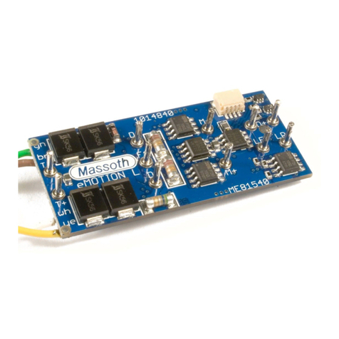
Massoth eMOTION LS User manual

Massoth

Massoth eMOTION LS User manual

Massoth eMOTION S User manual

Massoth

Massoth eMOTION S User manual

Massoth eMOTION XLS User manual

Massoth

Massoth eMOTION XLS User manual

Massoth eMOTION XLS User manual

Massoth

Massoth eMOTION XLS User manual

Massoth 8176001 User manual

Massoth

Massoth 8176001 User manual

Massoth eMOTION XLS User manual

Massoth

Massoth eMOTION XLS User manual

Massoth eMOTION XLS-Onboard User manual
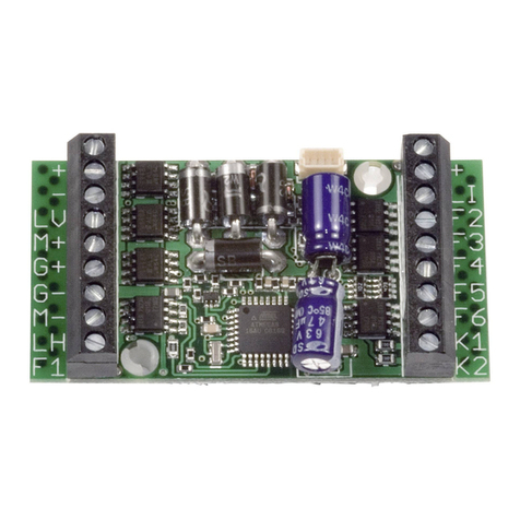
Massoth

Massoth eMOTION XLS-Onboard User manual

Massoth eMOTION 10FX User manual

Massoth

Massoth eMOTION 10FX User manual

Massoth DiMAX 1-Channel Switch Decoder II User manual

Massoth

Massoth DiMAX 1-Channel Switch Decoder II User manual

Massoth eMOTION LS User manual

Massoth

Massoth eMOTION LS User manual

Massoth eMOTION XXL User manual

Massoth

Massoth eMOTION XXL User manual

Massoth eMOTION XL II Instruction sheet

Massoth

Massoth eMOTION XL II Instruction sheet

Massoth eMOTION M User manual

Massoth

Massoth eMOTION M User manual

Massoth eMOTION S PluG User manual

Massoth

Massoth eMOTION S PluG User manual

Massoth eMOTION Melody User manual

Massoth

Massoth eMOTION Melody User manual

Massoth eMOTION XL II PluG Loco User manual

Massoth

Massoth eMOTION XL II PluG Loco User manual

Massoth eMOTION XL User manual

Massoth

Massoth eMOTION XL User manual

Popular Media Converter manuals by other brands

TR-Electronic LMR-70-180 ANA-I+JUSTAGE manual

TR-Electronic

TR-Electronic LMR-70-180 ANA-I+JUSTAGE manual

CNET CNFC-202 Specifications

CNET

CNET CNFC-202 Specifications

Video Products VGA-CMP installation guide

Video Products

Video Products VGA-CMP installation guide

CYP CP-255ID Operation manual

CYP

CYP CP-255ID Operation manual

Vital Systems pn7737 manual

Vital Systems

Vital Systems pn7737 manual

Contemporary Research QMOD-SDI HDMI product manual

Contemporary Research

Contemporary Research QMOD-SDI HDMI product manual

PCB Piezotronics 422E02 Installation and operating manual

PCB Piezotronics

PCB Piezotronics 422E02 Installation and operating manual

BE Ag & Industrial Agri Ease BE-LS35TLE270GX Operations & parts manual

BE Ag & Industrial

BE Ag & Industrial Agri Ease BE-LS35TLE270GX Operations & parts manual

Moxa Technologies UPORT 1200 series Quick installation guide

Moxa Technologies

Moxa Technologies UPORT 1200 series Quick installation guide

GearMo GM-482422 user manual

GearMo

GearMo GM-482422 user manual

Converters.TV CDM-680 Operation manual

Converters.TV

Converters.TV CDM-680 Operation manual

Binder 8012-0589 installation manual

Binder

Binder 8012-0589 installation manual

Phoenix Contact QUINT4-PS/12-24DC/24DC/1.3/SC manual

Phoenix Contact

Phoenix Contact QUINT4-PS/12-24DC/24DC/1.3/SC manual

ATEN IEEE-488/Parallel Converter IC-488P user manual

ATEN

ATEN IEEE-488/Parallel Converter IC-488P user manual

YOKOGAWA EXA DO402G instruction manual

YOKOGAWA

YOKOGAWA EXA DO402G instruction manual

SRS Lighting DST4H-3 instruction manual

SRS Lighting

SRS Lighting DST4H-3 instruction manual

Ltech LT-8048 quick start guide

Ltech

Ltech LT-8048 quick start guide

NTI VOPEX Series Installation and operation manual

NTI

NTI VOPEX Series Installation and operation manual

manuals.online logo
manuals.online logoBrands
  • About & Mission
  • Contact us
  • Privacy Policy
  • Terms and Conditions

Copyright 2025 Manuals.Online. All Rights Reserved.