METER WP4C User manual

WP4C

i
TABLE OF CONTENTS
1. Introduction.............................................................................................. 1
2. Operation ...................................................................................................2
2.1 Installation ................................................................................................2
2.2 Preparing Samples.....................................................................................3
2.3 Checking Sample Temperature ..................................................................4
2.4 Taking a Reading........................................................................................ 4
3. System......................................................................................................... 6
3.1 Specifications............................................................................................6
3.2 Components ..............................................................................................8
3.2.1 Sample Chamber.............................................................................. 9
3.2.2 LED ................................................................................................ 10
3.2.3 Buttons.......................................................................................... 10
3.2.4 Display Screen ............................................................................... 11
3.2.5 Reading Modes .............................................................................. 14
3.2.6 Computer Interface........................................................................ 15
3.3 Theory...................................................................................................... 16
3.3.1 Defining Water Potential ............................................................... 16
3.3.2 Measuring Water Potential ............................................................ 17
4. Service....................................................................................................... 19
4.1 Calibration ............................................................................................... 19
4.1.1 Verification Standards ................................................................... 19
4.1.2 Calibration Process........................................................................ 19
4.2 Maintenance............................................................................................ 21
4.3 Cleaning................................................................................................... 21
13588-06
4.30.2019

ii
4.4 Repair ...................................................................................................... 25
4.5 Troubleshooting ....................................................................................... 26
4.6 Customer Support.................................................................................... 28
4.7 Terms and Conditions .............................................................................. 28
Further Reading.......................................................................................... 29
Index ................................................................................................................. 32

WP4C
Dewpoint PotentiaMeter

1
1. INTRODUCTION
Thank you for choosing the WP4C Dewpoint PotentiaMeter from METER Group.
WP4C is a fast, accurate, and reliable way to measure water potential using the chilled-
mirror dew point technique. This manual includes instructions for setting up, calibrating, and
maintaining the WP4C. This manual also explains the basic concepts of water potential.
Verify all WP4C components are included and appear in good condition:
• WP4C unit
• Power cord
• RS-232 to USB cable
• 25 plastic sample cups and lids
• 10 stainless steel sample cups
• 12 vials of 0.50 mol/kg potassium chloride (KCl) verification standard
• Cleaning kit

2
OPERATION
2. OPERATION
Please read all instructions before operating the WP4C to ensure it performs to its full
potential.
PRECAUTIONS
METER instruments are built to the highest standards, but misuse, improper protection,
or improper installation may damage the sensor and possibly void the manufacturer’s
warranty. Before setting up the WP4C, follow the recommended installation instructions
and arrange proper protections to safeguard the instrument from damage.
2.1 INSTALLATION
Follow the steps listed in Table 1 to set up the WP4C.
Table 1 Installation
Tools Needed Portable 12-V power inverter (field installation)
Preparation
Select Clean, Level Location
Select a location where the temperature remains fairly stable to avoid
temperature changes that can affect accuracy (away from air conditioner and
heater vents, open windows, etc.). If in the field, a Styrofoam box, for example,
can help minimize temperature effects.
Observe clean practices to prevent contamination of the sample chamber.
Maintain a level surface to reduce the chance of spilling sample material and
contaminating the sample chamber.
Remove Sample Cup
Pull open the sample drawer by turning the knob to the OPEN/LOAD position.
Remove the empty upside-down disposable sample cup (used to protect the
drawer during shipment) and set aside.
Installation
(continued)
Plug In Instrument
Plug the power cord into the back of the WP4C unit and an outlet. Use only the
supplied power cord.
If in the field, plug the instrument into a 12-V portable power inverter that plugs
into the 12 V output of a vehicle.The inverter should have a continuous output of
at least 140 W.
NOTE: When the instrument is on, it draws up to 1 A. Check the battery rating to determine
how long it will power the instrument (for example, if the battery is rated for 60 Ah, it will
work for 60 h when the vehicle is not running).
WARNING: An incorrect main power voltage can damage the instrument.
Turn the Unit ON.
The ON/OFF switch is located on the lower right corner of the WP4C back panel.
Allow the WP4C a 15- to 30-min warm-up period to ensure accurate readings.
Check the calibration of the instrument (Section4.1).

3
WP4C
2.2 PREPARING SAMPLES
Proper sample preparation is important to keep the WP4C internal sensors clean and
achieve repeatable results. Carefully prepare and load samples to lengthen the time
between cleanings and help avoid downtime. Be consistent in sample preparation methods
to obtain reproducible results.
Considerations regarding sample temperature are discussed in Section2.3.
NOTE: Calibrate the WP4C (Section4.1) using the same type of sample cup that will be used for subsequent
measurements.
Follow the steps listed below to prepare samples.
1. Choose an appropriate sample cup.
METER recommends using stainless steel cups because stainless steel cups come to
temperature equilibrium with the sample block more quickly, leading to a more accurate
measurement. Only use disposable plastic cups for dry samples.
NOTE: Soil samples can be oven dried directly in the stainless steel cups to determine water content
gravimetrically, which is convenient if generating soil moisture characteristic curves.
2. Place the sample in the sample cup.
a. Completely cover the bottom of the cup, if possible, to provide enough sample to get
an accurate reading.
The WP4C may not be able to accurately measure a sample that does not (or cannot)
cover the bottom of the cup. A larger sample surface area speeds up the reading by
shortening the time needed to reach vapor equilibrium. It also increases instrument
accuracy by providing more stable infrared sample temperature measurements.
b. Do not fill the sample cup more than half full.
Overfilled cups may contaminate the sensors in the chamber.
3. Wipe any excess sample material from the rim of the cup with a clean KIMWIPES®tissue.
Material left on the rim or the outside of the cup will prevent a vapor seal with the
sensor block and will contaminate subsequent samples.
4. If a sample cannot be read immediately, put the disposable sample cup lid on the cup to
restrict water transfer.
For longer term storage, seal the lid by placing tape or Parafilm®laboratory film
completely around the cup to lid junction.
Thoroughly clean the stainless steel cups using deionized water between uses to prevent
solutes from contaminating subsequent samples and causing artificially negative osmotic
potential.
The WP4C can be used to measure the water potential of leaves and plant material. Refer
to the application note Easy, accurate measurement of leaf water potential using the WP4C
(metergroup.com/environment/articles/measurement-leaf-water-potential-using-wp4c/).

4
OPERATION
2.3 CHECKING SAMPLE TEMPERATURE
For an accurate measurement, the sample temperature (Ts) should be close to the
sample block temperature (Tb). WP4C displays the temperature difference in the sample
temperature screen.
If a sample is warmer than the sample chamber (Ts-Tb is a positive number), condensation
may occur and moisture may condense inside the block, which will adversely affect readings.
If a sample is colder than the sample block temperature (Ts-Tb is a negative number), the
WP4C will wait to start a reading until its temperature increases to 1 °C below sample block
temperature. The closer the sample temperature is to the sample block temperature (i.e.,
closer to equilibrium), the less time is need for a reading.
To ensure the sample is at the correct temperature, use the following steps.
1. Place the sample in the chamber and close the drawer.
2. Press the lower right button to access the sample temperature screen and view the
temperature difference.
3. If the sample temperature difference is between −0.5 and 0, the sample can be used to
begin a reading (Section2.3).
If the sample temperature difference is a positive number, remove the sample
immediately.
4. Set the sample on a cold surface and cover with the cup lid to preserve the moisture.
Leave for approximately 1 min.
Do not cool the sample too much or the equilibrium time will be lengthened.
5. Place the sample back in the chamber and note the temperature difference again.
If it is between −0.5 and 0, begin the reading (Section2.4).
2.4 TAKING A READING
Observe the following cautions and use the following steps to take a reading.
CAUTIONS
• Ensure that the physical temperature of the WP4C is between 5 °C and 40 °C.
• Do not measure a sample that has a temperature greater than the WP4C chamber
(Section2.3). Remove the sample until it is at room temperature.
• Do not move the sample drawer too quickly when loading or unloading samples to avoid
spilling.
• Never try to move the instrument after a sample is loaded. Movement may cause the
sample material to spill and contaminate the sample chamber.
• Never leave a sample in the WP4C after a reading has finished. The sample may spill and
contaminate the instrument chamber if the instrument is accidentally moved or jolted.

5
WP4C
• Consult troubleshooting (Section4.5) if the triangular warning symbol appears in the top
right corner of the display (Figure1).
Figure1 Triangular warning sign
Perform the following steps to take a reading.
1. Turn the drawer knob to OPEN/LOAD and pull the drawer out.
2. Place the sample in the sample drawer and carefully slide the drawer closed to avoid
spilling solution and contaminating the chamber.
3. Check to be sure the sample temperature is below chamber temperature (lower right
button).
4. Turn the drawer knob to the READ position.
A notification that the measurement is starting will appear (Figure2).
Figure2 Measurement starting notification
Values display the initial measurements being taken and the Main screen will update
values throughout the reading. WP4C signals when it reaches the final values by a green
LED flash and an audible notification (if enabled). The WP4C will display the final water
potential and temperature of the sample (Figure3).
Figure3 Results screen

6
SYSTEM
3. SYSTEM
This section describes the specifications, components, and theory of the WP4C instrument.
3.1 SPECIFICATIONS
MEASUREMENT SPECIFICATIONS
Water Potential
Range 0 to –300 MPa
Resolution NA
Accuracy ±0.05 MPa from 0 to –5 MPa
1% from –5 to –300 MPa
NOTE: All vapor pressure instruments (including the WP4C) are limited by accuracy in the wet end of the water
potential range. The range of 0 to −5 MPa has an accuracy of ±0.05 MPa. For example, a measurement of −0.1 MPa
has an accuracy of ±50% of the measurement and a measurement of −1 MPa has an accuracy of ±5%.The WP4C will
not measure water potential accurately near field capacity (-0.033 MPa).
Temperature
Range 15-40 °C
Resolution 0.1 °C
Accuracy ±0.2 °C
Read Time
Soil sample
~10–15 min (precise mode)
<5 min (fast mode)
NOTE: WP4C will display updated measurements approximately every 5 min until
stopped.
Plant sample ~20 min
PHYSICAL SPECIFICATIONS
Case Dimensions
Length 24.1 cm (9.5 in)
Width 22.9 cm (9.0 in)
Height 8.9 cm (3.5 in)
Case Material
Powder painted aluminum

7
WP4C
Sample Cup Capacity
15 mL (0.5 oz) full
7 mL (0.25 oz) recommended
Weight
3.2 kg (7.1 lb)
Display
20 x 2 alphanumeric LCD with backlighting
Sensor Types
Chilled-mirror dew point sensor
Infrared temperature sensor
Operating Temperature
Minimum 5 °C
Typical NA
Maximum 40 °C
Data Communications
RS-232A serial
8-data bit ASCII code
9,600 baud, no parity
1 stop bit
Interface Cable
Standard RS-232 to USB cable (included)
Power
110–220 VAC
50/60 Hz
COMPLIANCE
Manufactured under ISO 9001:2015
EM ISO/IEC 17050:2010 (CE Mark)
Compatible standard: ASTM D6836-07

8
SYSTEM
3.2 COMPONENTS
The WP4C uses the chilled-mirror dew point technique to measure the water potential of
a sample. In an instrument that uses the dew point technique, the sample is equilibrated
with the headspace of a sealed chamber that contains a mirror and a means of detecting
condensation on the mirror. At equilibrium, the water potential of the air in the chamber is
the same as the water potential of the sample.
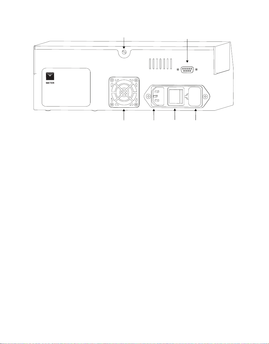
The WP4C main components include the display screen and sample chamber (Figure4 and
Figure5). A power cord and RS-232 communication cable can be plugged into the back of the
unit.
OPEN/LOAD
READ
LED
Function keys
Sample drawer
LCD screen
WP4C
Dewpoint PotentiaMeter
Figure4 Front view
9
WP4C
FanFuse well
ON/OFF
switch
Power
cord plug
Lidscrew RS-232 connection
Figure5 Back view
3.2.1 SAMPLE CHAMBER
The sample chamber has many components (Figure6). An internal thermoelectric module
equilibrates the sample temperature to the headspace of the chamber.
A thermoelectric (Peltier) cooler controls the mirror temperature. A photoelectric cell detects
the exact point when condensation first appears on the mirror by measuring a reflected
beam of light with a photodetector. The photodetector senses the change in reflectance
when condensation occurs on the mirror. A thermocouple attached to the mirror records the
temperature when condensation occurs.
An internal fan circulates the air within the sample chamber to reduce time to equilibrium.
Both dew point and sample surface temperatures are simultaneously measured, eliminating
the need for complete thermal equilibrium.

10
SYSTEM
Fan
IR thermometer
Optical sensor
Mirror
Locking levers
20-pin socket
Figure6 Sample chamber
3.2.2 LED
A flashing green LED, located on the left front corner of the WP4C case, blinks to notify the
user of different settings.
The LED flashes once when a sample reading starts. In Fast and Precise reading modes, the
LED will flash continuously when the sample reading is finished until the sample drawer
knob is moved to the OPEN/LOAD position. The LED settings cannot be changed or turned off.
3.2.3 BUTTONS
Four buttons flank the LCD screen (Figure7). The function of each button changes
depending on the current screen (Section3.2.4).
WP4C
Dewpoint PotentiaMeter
Figure7 Buttons

11
WP4C
3.2.4 DISPLAY SCREEN
The WP4C has five different screens to display data and change settings.
3.2.4.1. MODEL INFORMATION SCREEN
The Model Information screen (Figure8) will appear for approximately 3 s after turning the
WP4C on, immediately followed by the Main screen.
Figure8 Model Information screen
3.2.4.2. MAIN SCREEN
The Main screen (Figure9) displays the water potential in both megapascals and log-scaled
pF values. The sample temperature is displayed in degrees Celsius. The values on this
screen will update during measurements. A small letter in the top left indicates the reading
mode.
Reading mode Language screen
System Setup screen Sample Temperature screen
WP4C
Dewpoint PotentiaMeter
Figure9 Main Menu screen and button functions
Pressing the upper left button will change the reading mode (Section3.2.5). The symbol on
the screen will toggle between p, c, or fto indicate if WP4C is reading in Precise, Continuous,
or Fast mode.
Press the upper right button to change the WP4C language (Section3.2.4.3).
Press the lower right button to show sample temperature information (Section3.2.4.4).
Press the lower left button to bring up system setup options (Section3.2.4.5).
NOTE: WP4C will not allow button selections while the unit is reading a sample.

12
SYSTEM
3.2.4.3. LANGUAGE SCREEN
The Language screen shows the current selected language for the unit. English is the WP4C
default on-screen language. The on-screen user language can be changed to any one of the
following languages: German, French, Spanish, Italian, Swedish, Danish, Norwegian, Czech,
Portuguese, Japanese, Polish, or Finnish.
From the Main screen, press the upper right button.The Language screen (Figure10) with
default English will appear. Continue pressing the upper right button to scroll through the
language options. When the preferred language is reached, press the lower left button to exit.
Figure10 English screen
3.2.4.4. SAMPLE TEMPERATURE SCREEN
The Sample Temperature screen (Figure11) displays the sample temperature (Ts) and the
temperature difference between the WP4C sample and the sample block (Ts - Tb). Use this
screen to quickly check if the sample is too hot, which may cause condensation inside the
chamber.
NOTE:It is important that Ts−Tb is negative in order to prevent condensation inside the sample chamber.
From the Main screen, press the lower right button to bring up the Sample Temperature
screen. Press either of the lower buttons to exit.
NOTE:The sample drawer knob must be in the OPEN/LOAD position to access the Sample Temperature screen.
Figure11 Sample Temperature screen
3.2.4.5. SYSTEM SETUP SCREEN
The System Setup screen is used to change how the WP4C signals after each reading, enter
the Calibration Menu, and set the Temperature (set T) (Figure12).
Figure12 System Setup screen

13
WP4C
From the Main screen, press the bottom left button to access this menu. Use the buttons to
select the desired setting to configure: audible notification, calibration, and temperature.
Press the upper left button to toggle adjust the audible notification at the end of a reading.
Three icons represent the three options: no notification (0x), beep momentarily before
stopping (4x), or beep continuously until the sample drawer knob is turned to the OPEN/
LOAD position.
NOTE: The audible notification is not changed by turning the instrument off and on.
Press the upper right button to go to start calibration (Section4.1).
Press the lower right button to set WP4C temperature (Section3.2.4.6)
Press the lower left button to exit back to the Main menu at any time.
3.2.4.6. TEMPERATURE SET SCREEN
The default temperature of the WP4C sample block temperature is 25 °C. The Temperature
Set screen allows the sample block temperature to be set manually (Figure13). The sample
block temperature roughly corresponds to the temperature needed to read the sample.
To access this screen from the Main menu, press the lower left button, followed by the lower
right button (next to set T) on the System setup screen.
Figure13 Temperature Set screen
The index number can be adjusted between 15 and 40 °C. Use the right buttons next to the +
and −symbols to adjust the sample block temperature value in increments of 0.1 °C.
NOTE:Holding down the button will rapidly increment the value.
The temperature control can be disabled by pressing the −button after reaching 15 °C.
Reenable temperature control by pressing the +button to bringing the sample block
temperature back into its controllable range.
After adjusting the sample block temperature, wait 15 min before taking a measurement to
allow the sample block to reach the new temperature.
3.2.4.7. PERFORMANCE EVALUATION SCREEN
The Performance Evaluation screen needs to be accessed only if one of the components
of the WP4C may be causing a measurement error. Before accessing this screen, ensure
the instrument has been cleaned (Section4.3) and other troubleshooting steps have been

14
SYSTEM
reviewed (Section4.5). Values on this screen cannot be changed, but they will indicate
component performance. If any of these values are not what they should be, contact
Customer Support.
To access this screen, hold down the lower right button while turning on the instrument.
After the instrument initializes, the Performance Evaluation screen will appear, providing
four values (Figure14).
Figure14 Example Performance Evaluation screen
• The top left value is the value the thermocouple is reading—the temperature difference
between the sample block and the mirror. If this is 0, there is something wrong with the
thermocouple.
• The top right value is the value read by the thermopile—the temperature difference
between the sample block and the sample. This value is variable but should never be 0.
• The bottom left value is the sample block temperature. This value should be around
ambient temperature.
• The bottom right value is the mirror reflectance voltage, in volts. This value should normally
be around 0.5 or above, but if it drops below 0.3, there is something wrong.
Press the button next to –Exit– to bring up the Main menu.
3.2.5 READING MODES
WP4C has three reading modes: precise, continuous, or fast. The display will show a small
p, c, or fto the left of the water potential readings (Figure15) indicating which mode is
selected. To change the mode, navigate to the Main screen and press the upper left button.
NOTE: WP4C will not allow button selections while the unit is reading a sample.
Figure15 Main Menu with Continuous mode enabled
PRECISE MODE
Precise mode is the default WP4C mode. WP4C repeats sample measurements until
successive readings agree within a preset tolerance (0.03 MPa for Ψ> −40 MPa; otherwise
0.3 MPa). For most accurate results, run most soil samples in Precise mode. Typical read
times are within 10 to 15 min.

15
WP4C
CONTINUOUS MODE
Continuous mode measures the water potential of the sample continuously until the drawer
knob is turned back to the OPEN/LOAD position. The WP4C will measure the sample, display
the water potential and sample temperature, then begin another read cycle. WP4C will
signal the end of a reading with an LED flash and audible notification (if enabled).
Continuous mode is recommended for samples that take a long time (20 to 30 min) to come
to vapor equilibrium, such as plant samples and wet soil samples with water potential
>−0.5 MPa. METER recommends using Continuous mode and logging data to determine when
equilibrium conditions are reached. It may be helpful to connect the WP4C to a computer
while in Continuous mode in order to log and store data over time (Section3.2.6).
FAST MODE
Fast mode measures the sample once. Read time is typically 3 to 5 min. Readings are less
precise, particularly in the wet range.
Fast mode is recommended for dry soil samples with water potential <−40 MPa. For samples
with very little water holding capacity (i.e., dry sand samples), small leaks in the sample
chamber can cause water potential to drift down over time.
3.2.6 COMPUTER INTERFACE
The WP4C can connect to a computer to send water activity data to a computer for further
analysis and storage. An RS-232-to-USB serial cable is included for this purpose. The
interface is run through the AquaLink 4 Software or a terminal communication program.
NOTE:If the computer does not have a USB port, use a USB-to-RS-232 adapter.
There are several terminal program options. METER has its own terminal program (DecaTerm)
that can be downloaded from metergroup.com/wp4c-support. Two other options are
TeraTerm, a free program that can be found on the internet, and Hyperterminal, the standard
program with Microsoft®Windows®prior to Windows 7 software.
To integrate a terminal program with WP4C, use the following steps:
1. Power on the WP4C.
2. Connect the USB interface cable to the computer.
3. Follow the instructions for the program with the following settings:
c. Choose correct COM Port.
d. Set or verify COM Properties.
e. Bits per second (Baud rate): 9,600
Data: 8 bit
Parity: none
Stop: 1 bit
Flow control: none

16
SYSTEM
Upon successful completion of a water activity reading, the data in the terminal program
displays measurement time (in minutes), sample temperature, and water potential (in both
megapascals and picofarad). Figure16 shows a sample return.
Figure16 Sample data return
3.3 THEORY
Water potential is a measurement of the energy status of the water in a system. It
indicates how tightly water is bound, structurally or chemically, within a substance.
Water potential is defined as the potential energy per unit volume of water in a sample.
3.3.1 DEFINING WATER POTENTIAL
The total water potential of a sample is the sum of four component potentials:
gravitational, matric, osmotic, and pressure. Gravitational potential depends on the
position of the water in a gravitational field. Matric potential depends on the adsorptive
forces binding water to a matrix. Osmotic potential depends on the concentration of
dissolved substance in the water. Pressure potential depends on the hydrostatic or
pneumatic pressure on the water.
The WP4C measures the sum of the osmotic and matric potentials in a sample. Often
one or the other of these potentials will be the dominant factor in determining the total
potential. For example, solutions like the KCl calibration standard have only an osmotic
component. Soils bind water mainly through matric forces and therefore have mainly a
matric component (though salt-affected soils can have a significant osmotic component).
Table of contents
Other METER Measuring Instrument manuals

METER
METER PROCHECK User manual

METER
METER AQUALAB PAWKIT User manual

METER
METER SI-400 Series User manual

METER
METER AQUALAB VSA User manual

METER
METER AQUALAB TDL User manual

METER
METER AQUALAB User manual

METER
METER TEROS 54 User manual

METER
METER ACCUPAR LP-80 User manual

METER
METER TEROS 06 User manual

METER
METER THERMOLINK User manual

METER
METER APOGEE SU-221 User manual

METER
METER AQUALAB TDL User manual

METER
METER TEROS 11 User manual

METER
METER ROS 1 User manual

METER
METER TEMPOS User manual

METER
METER TEROS 32 User manual

METER
METER ATMOS 22 User manual

METER
METER AQUALAB PAWKIT User manual

METER
METER APOGEE SQ-521 User manual

METER
METER SC-1 User manual


