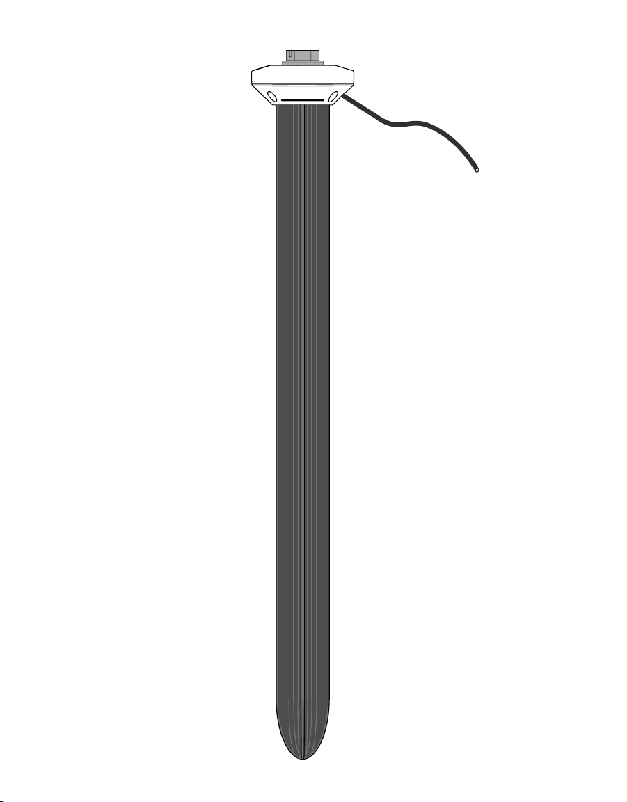
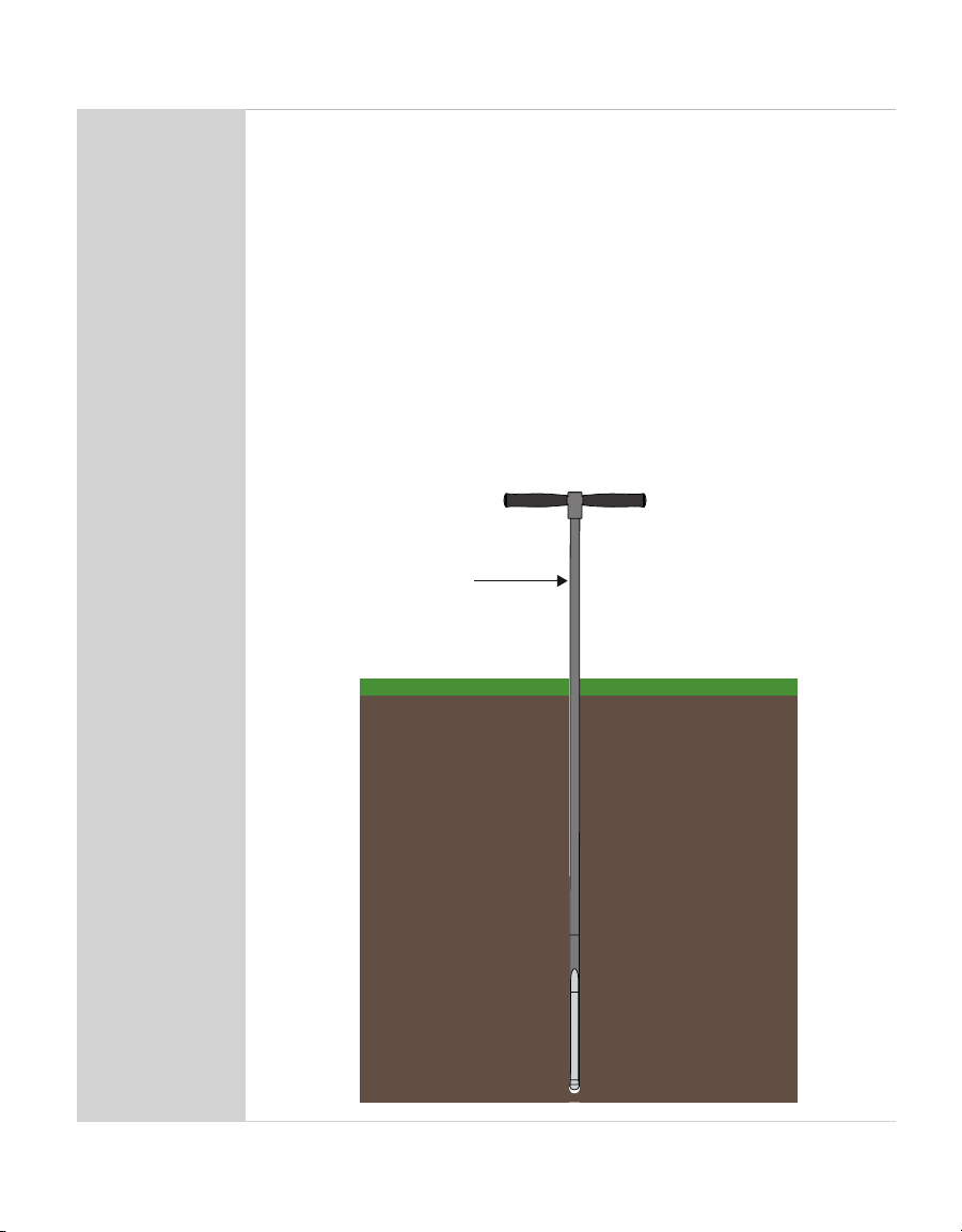
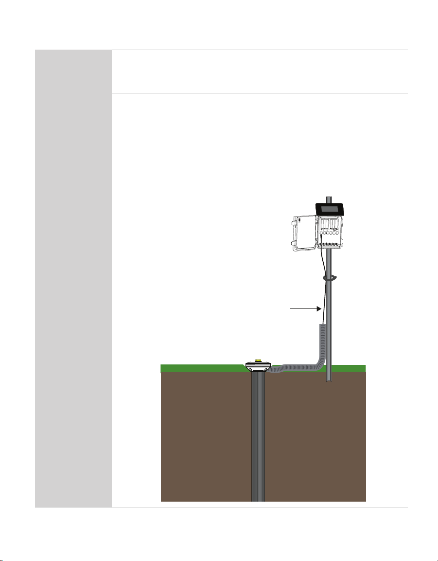
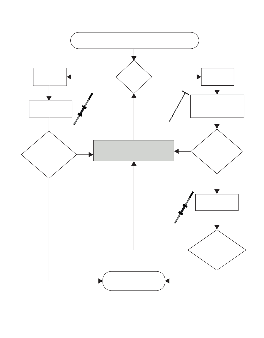
METER TEROS 54 User manual

i
TABLE OF CONTENTS
1. Introduction.............................................................................................. 1
2. Operation ...................................................................................................2
2.1 Installation ................................................................................................2
2.1.1 Overview ..........................................................................................2
2.1.2 Installation Methods........................................................................6
2.2 Connecting............................................................................................... 11
2.2.1 Connect to METER Data Logger...................................................... 12
2.2.2 Connect to Non-METER Data Logger.............................................. 12
2.3 Communication ....................................................................................... 14
2.4 Removal................................................................................................... 15
3. System....................................................................................................... 20
3.1 Specifications.......................................................................................... 20
3.2 Components ............................................................................................ 24
3.3 Theory...................................................................................................... 27
3.3.1 Volumetric Water Content.............................................................. 27
3.3.2 Temperature .................................................................................. 27
4. Service....................................................................................................... 28
4.1 Calibration ............................................................................................... 28
4.1.1 Mineral Soils.................................................................................. 28
4.1.2 Apparent Dielectric Permittivity .................................................... 29
4.2 Maintenance............................................................................................ 29
4.3 Troubleshooting....................................................................................... 29
4.4 Customer Support.................................................................................... 31
4.5 Terms and Conditions .............................................................................. 31
18511-00
3.2023


1
TEROS 54
1. INTRODUCTION
Thank you for choosing the TEROS 54 Soil Water Content Profile probe from METER Group.
The TEROS 54 probe is designed to be installed in mineral soils, a variety of growing media,
and other porous materials. This manual describes how to use the probe and guides the
customer through the probe features.
The TEROS 54 probe is an accurate tool for monitoring volumetric water content (VWC)
using capacitance and frequency-domain technology. The sensors use a 70 MHz frequency
to minimizes textural and salinity effects that makes the TEROS 54 accurate in most
mineral soils.
The TEROS 54 uses four precision-integrated temperature sensors to measure temperature
in soil and soilless substrates.
Verify all TEROS 54 components are included and appear in good condition:
1. TEROS 54 probe
2. Protective cap
METER recommends testing sensors with the data aquisition device and software before
going to the field.

2
OPERATION
2. OPERATION
Please read all instructions before operating the TEROS 54 to ensure it performs to its full
potential.
PRECAUTION
METER sensors are built to the highest standards, but misuse, improper protection, or improper installation may
damage the sensor and possibly void the manufacturer’s warranty. Before integrating TEROS 54 into a system, make
sure to follow the recommended installation instructions and have the proper protections in place to safeguard
sensors from damage. If installing sensors in a lightning-prone area with a grounded data logger, see the application
note Lightning surge and grounding practices.
2.1 INSTALLATION
This sections contains an overview of the TEROS 54 installation procedure (Section2.1.1)
and detailed information about the pile (slide) hammer (Section2.1.2)
2.1.1 OVERVIEW
Table1 contains information needed to install the TEROS54 and start collecting data.
Table1 Installation
Tools Needed
TEROS 54 auger
Dead blow hammer
Pile hammer (slide hammer)
PVC casing or flexible conduit (to protect cables)
Level (to check that the auger is level while digging the hole for the probe)
Preparation
Consider the Surroundings
When selecting a suitable location for the TEROS 54, make sure that it is a
representative location in the measurement area.
Avoid installation in very rocky soils, if possible, to prevent damage to the
TEROS 54.
Conduct System Check
Plug the probe into the logger (Section2.2) to make sure the probe is functional.
Check Sensor Functionality
Verify all sensors read within expected ranges. To validate both probe
and logger functionality, take probe measurements in air and water.
The value of permittivity in air should be 1.
NOTE: The sensors will not read 100% water content in water.

3
TEROS 54
Table 1 Installation (continued)
Installation
Create Hole
To install the TEROS 54 into the soil, use the TEROS 54 auger available from
METER (Section2.1.2) to drill a vertical hole in the soil. Use a level on the auger
to make sure the hole is drilled vertically to prevent damage to the probe.
NOTE: METER recommends using the TEROS 54 auger and slide hammer that are designed
specifically for installing the TEROS 54 in compact, firm soil.This method will result in good
soil contact. The TEROS 54 can only be installed in very loose, sandy, and soft soils without
using the TEROS54 auger.
• Avoid interfering with large objects like roots or rocks that could potentially
damage the probe housing.
• Installations near large metal objects can affect the sensor's function and
distort readings.
NOTE: Never drill to the final depth in one step. Remove the soil from the auger
approximately every 30 cm.
Mark the required drilling depth on the TEROS 54 auger extension rod.
Themaximum depth the auger can go is 70 cm.
Auger
maximum digging
depth = 70 cm

4
OPERATION
Table 1 Installation (continued)
Installation
(continued)
Installation Tool
CAUTION
When using the slide hammer to install the TEROS 54 probe, please wear proper ear
protection to prevent hearing damagße because the hammer is quite loud. Please wear
gloves to protect hands from being pinched.
When the hole has been drilled to its final depth, position the TEROS 54
centered over the hole, tip-first, and press it down vertically.
NOTE: Do not try to insert the TEROS 54 to the desired depth by pushing down by hand.
For installation, METER highly recommends the slide hammer, available
from METER.
Place the slide hammer with the attachment on the TEROS 54 probe head and
drop the weight several times to install the TEROS 54 gradually into the soil.
Raise up
Drop down
slide hammer
drop weight
(slideable)
probe head
NOTE: During installation, make sure that no air gaps occur between soil and the probe
housing. Gaps, such as air pockets near the probe housing, can have a negative effect on
the measurement and falsify the measured values.

5
TEROS 54
Table 1 Installation (continued)
Installation
(continued)
Finally, screw the protective cap into the thread to protect it from
environmental influences.
NOTE: Do not hit the probe head directly with a hammer.This can damage the probe head.
Installation
(continued)
Secure and Protect Cables
NOTE: Improperly protected cables can lead to severed cables or disconnected probes.
Cabling issues can be caused by many factors such as rodent damage, driving over probe
cables, tripping over cables, not leaving enough cable slack during installation, or poor
probe wiring connections (Section2.1.2).
Install cables in conduit or plastic tubing when near the ground to avoid
rodent damage.
Gather and secure cables between the TEROS 54 and the data logger to the
mounting mast in one or more places.
Port1Port2Port3Port4 Port 5Port6
TEST
OK
ERROR
(-)
(-)(-) (-)
(-)(+)(-)(+)(+)
(+)(+)(+)
Cable

6
OPERATION
Table 1 Installation (continued)
Installation
(continued)
Connect to Logger
Plug the probe into a data logger.
Use the data logger to make sure the sensors are reading properly.
Verify that these readings are within expected ranges.
For more instructions on connecting to data loggers, refer to Section2.2.
2.1.2 INSTALLATION METHODS
This section explains installation methods METER recommends for different soil
conditions (Figure1).
The TEROS 54 probe can only be installed in very loose, sandy, and soft soils without the
TEROS54 auger.
METER recommends using the TEROS 54 auger and slide hammer that are designed
specifically for installing the TEROS 54 in compact, firm soil. This method will result in good
soil contact.
• The TEROS 54 auger is shaped to prevent soil compaction near the probe elements
(Figure2).
• The slide hammer (Figure3) consists of four parts: handle, rod, weight (approx. 4 kg
[8.82 lbs]) and connector (put on the TEROS 54 head). Because there is a predetermined
distance that the slide hammer weight travels when dropped, there is an even distribution
of force delivered.

7
TEROS 54
If installation is not possible,
choose another location.
Soft,
loose soil
Compact,
firm soil
Install using
slide hammer
Choosing the right installation method
Soil
condition
Installed
Predrilling
successful?
No
Predrill hole using
TEROS 54
specific auger
Sensor head
contacts soil?
No
Yes
Yes
Sensor head
contacts soil?
Yes
No
Install using
slide hammer
Figure1 Choosing the right installation method

8
OPERATION
CAUTION
When using the slide hammer to install the TEROS 54 probe, please wear proper ear protection to prevent hearing
damage because the hammer is quite loud.Please wear gloves to protect hands from being pinched.
Auger tip
Auger handle
Handle
Rod
Drop weight
(slideable on the r
od)
Connector
Figure2 TEROS 54 auger Figure3 TEROS 54 slidehammer

9
TEROS 54
CAUTION
Never hit the head of the TEROS 54 with a regular hammer. This can damage the probe.Only use the dedicated slide
hammer tool from METER.
The following steps detail how to use the TEROS 54 auger:
1. Assemble the auger using the handle and auger tip.
2. Mark the probe length 70 cm on the auger rod.
NOTE: Do not dig deeper than 70 cm to ensure that the probe is in good contact with the soil after installation.
3. Place the auger tip on the ground.
4. Place a level vertically on the rod of the auger.
5. Check the level for the proper angle until the auger tip is in far enough so the angle does
not change.
6. Hit the handle gently a few times with a dead blow hammer until the auger tip is 30 cm
in the soil.
7. Rotate the auger one revolution to cut off the soil in the borehole.
8. Pull the auger out of the borehole after 30 cm to avoid soil compaction.
9. Remove the soil inside the auger tip.
10. Place the auger back into the borehole to the previous depth.
11. Repeat step6 through step10 until the desired depth (maximum is 70 cm) is reached.
After drilling a hole for the TEROS 54, place the TEROS 54 with the pointed side (probe tip)
centered over the hole. Press the TEROS 54 as deep as possible into the soil and use the
slide hammer (available from METER) to help with installation in firm, compact soils.
1. Place the slide hammer vertically and centered on the head of the TEROS 54.
2. Bring the weight to approx. half the drop height.
3. Release the weight.
4. Repeat step2 and step3 until the TEROS 54 has reached its intended depth.
NOTE: The TEROS 54 should be driven approximately 1.0 cm (0.39 in) deep into the soil per drop. Increase the
drop height only if the installation comes to a standstill or the probe is being driven less than 1.0 cm per drop. In
that case, lift the weight all the way up to its maximum height.
NOTE: Allow the weight of the drop hammer to fall by gravity only, do not extend the drop distance or increase
the impact force by pushing or using a heavier weight.
NOTE: If the TEROS 54 cannot be installed to the intended depth due to rocky compact soil conditions, do not
use force, but change the installation location to avoid damaging the probe!
After installing the TEROS 54 in the soil to its maximum installation depth (the head of
the TEROS 54 should be approximately 5 mm deep in the soil), attach the protective cap
(Figure5) to the sensor head and connect the TEROS 54 to a data logger (Section2.2).

11
TEROS 54
5 mm
protective cap
Figure5 TEROS 54 head installation view
2.2 CONNECTING
The TEROS 54 works seamlessly with METER ZENTRA data loggers, and it can also be used
with other data loggers, such as those from Campbell Scientific, Inc. For extensive directions
on how to integrate the sensors into third-party loggers, refer to the TEROS 54 Integrator Guide.
TEROS 54 probes require an excitation voltage in the range of 4.0- to 24.0 VDC and
operate at a 3.6-VDC level for data communication. TEROS 54 can be integrated using
DDI Serial, SDI-12, Modbus RTU, or tensioLINK communications protocol. Refer to the
TEROS54 Integrator Guide for details on interfacing with data acquisition systems.
TEROS 54 probes come with a 3.5-mm stereo plug connector (Figure6) to facilitate easy
connection with METER loggers. TEROS 54 probes may be ordered with stripped and
tinned wires to facilitate connecting to somethird-party loggers (Section2.2.2). A 1.5 M
cable is also available for use with an M12 connector.
To probe
or sensor
3.5-mm stereo connector Pigtail adapter Stripped and tinned wire
Ground
Digital communication (orange)
Power (brown)
Ground (bare)
Digital communication (orange)
Power (brown)
Figure6 Three-wire stereo connector and pigtail adapter

12
OPERATION
The TEROS 54 comes standard with a 5-m cable. It may be purchased with custom cable
lengths for an additional fee (on a per-meter basis). In some instances, the cable can be
extended beyond 75 m by the user, but this is discouraged for a variety of reasons. Please
contact Customer Support for more details before extending or splicing cables.
2.2.1 CONNECT TO METER DATA LOGGER
The TEROS 54 works most efficiently with METER ZENTRA series data loggers. Check the
METER download webpage for the most recent data logger firmware. Logger configuration
may be done using either ZENTRA Utility (desktop and mobile application) or ZENTRA Cloud
(web-based application for cell-enabled ZENTRA data loggers).
1. Plug the 3.5-mm stereo plug connector into one of the sensor ports on the logger.
2. Using the appropriate software application, configure the chosen logger port for the
TEROS54.
METER data loggers will automatically recognize TEROS54 probes.
3. Set the measurement interval.
METER data loggers measure the TEROS 54 every minute and return the average of the
1-min data across the chosen measurement interval.
TEROS 54 data can be downloaded from METER data loggers using either ZENTRA Utility or
ZENTRA Cloud. Refer to the logger user manual for more information about these programs.
2.2.2 CONNECT TO NONMETER DATA LOGGER
The TEROS 54 can be used with non-METER (third-party) data loggers. Refer to the third-
party logger manual for details on logger communications, power supply, and ground ports.
The TEROS 54 Integrator Guide also provides detailed instructions on connecting sensors to
non-METER loggers.
TEROS54 probes can be ordered with stripped and tinned (pigtail) connecting wires for
use with screw terminals. METER recommends using a 4-pin M12 plug connector and a
connection cable with open wires for use with a non-METER data logger using either SDI-12,
tensioLINK serial, or Modbus RTU communications protocol.
Connect the TEROS 54 wires to the data logger as illustrated in Figure7 with the supply wire
(brown) connected to the excitation, the digital output wire (orange) to a digital input, and the
bare ground wire to ground.
NOTE: The acceptable range of excitation voltages is from 4.0 to 24.0 VDC.To read TEROS 54 with Campbell Scientific,
data loggers,power the sensors from a switched 12-V port or a 12-V port if using a multiplexer.

13
TEROS 54
Excitation Digital in
SDI-12
3-wire
SDI-12
Data Logger
Ground
Digital
communication
(orange)
Ground
(bare)
Power
(brown)
Figure7 Three-wire SDI-12 pigtail wiring digram
For RS-485, the power supply wire (brown) will be connected to the excitation, the digital
communication +wire (white) to a digital input (high), the digital communication –wire
(black) to a digital input (low) and the blue ground wire to ground. For SDI-12, both the digital
communication –and ground wires will both be connected to ground.
PIN 4 RS-485-B (black)
Shield
(black)
PIN 3 Ground (blue)
PIN 2 RS-485-A/SDI-12 (white)
PIN 1 Power + (brown)
3
4
12
Male plug on
sensor cable
From
probe or
sensor
Figure8 Four-wire M12 connector and pigtail adapter for use with screw terminals
Excitation Digital in
RS-485-A (+)
4-wire M12
RS-485
Data Logger
Ground
Digital
communication
(white)
Ground
(blue)
Power
(brown)
Digital in
RS-485-B (–)
Digital
communication
(black)
Figure9 Four-wire M12 connector RS-485 wiring diagram

14
OPERATION
Excitation Digital in
SDI-12
4-wire M12
SDI-12
Data Logger
Ground
Digital
communication
(white)
Ground
(blue, black)
Power
(brown)
Figure10 Four-wire M12 connector SDI-12 wiring diagram
If the TEROS 54 cable has a standard stereo plug connector and needs to be connected to a
non-METER data logger, use one of the following two options.
Option 1
1. Clip off the stereo plug connector on the probe cable.
2. Strip and tin the wires.
3. Wire it directly into the data logger.
This option has the advantage of creating a direct connection and minimizes the chance of
the probe becoming unplugged. However, it then cannot be easily used in the future with a
METER readout unit or data logger.
Option 2
Obtain an adapter cable from METER.
The adapter cable has a connector for the stereo plug connector on one end and three
wires (or pigtail adapter) for connection to a data logger on the other end. The stripped and
tinned adapter cable wires have the same termination as seen in Figure6: the brown wire is
excitation, the orange is output, and the bare wire is ground.
NOTE: Secure the stereo plug connector to the pigtail adapter connections using adhesive-lined heat shrink to ensure
the probe does not become disconnected during use.
2.3 COMMUNICATION
The TEROS 54 communicates using different methods:
• DDI Serial
• SDI-12 communications protocol
• Modbus RTU communications protocol
• tensioLINK serial

15
TEROS 54
To obtain detailed instructions, refer to the TEROS 54 Integrator Guide.
The SDI-12 protocol requires that all sensors have a unique address. The TEROS 54 sensor
factory default is an SDI-12 address of 0. To add more than one SDI-12 sensor to a bus, the
sensor address can be changed using a METER ZSC Bluetooth®sensor interface and the
ZENTRA Utility Mobile app as described below:
NOTE: The sensor SDI-12 address must be returned to 0to work with ZENTRA loggers.
1. Using a mobile device, open the ZENTRA Utility Mobile app.
2. Connect the sensor to the ZSC.
3. Under Sensor Information, select the SDI Address dropdown.
4. Scroll through the options and select the desired SDI-12 address.
NOTE: Address options include 0–9, A–Z, and a–z.
Detailed information can also be found in the application note Setting SDI-12 addresses on
METER digital sensors using Campbell Scientific data loggers and LoggerNet.
When using the sensor as part of an SDI-12 bus, excite the sensors continuously to avoid
issues with initial sensor startup interfering with the SDI-12 communications.
2.4 REMOVAL
Do not shake the TEROS 54 to remove it from the soil. Do not try to pull the TEROS 54 from
the borehole with bare hands.
To remove the TEROS 54, only use the TEROS 54 Removal Tool (Figure11) available from
METER, consisting of an eyebolt, a carabiner, a tensioning strap, a lever tool (pile puller), and
a base (serves as a foundation by inserting the lever tool).
Lever
Base
Carabiner Eyebolt
Tension strap
Figure11 Removal tool components

16
OPERATION
To operate the TEROS 54 Removal Tool, follow the steps below.
1. Remove the protective cap from the thread of the TEROS 54.
2. Screw the eyebolt into the thread.
3. Insert the vertical leg (A) of the lever tool into the base.
4. Connect the carabiner to the eyebolt.
5. Gently pull the TEROS 54 out of the soil by pressing down on the lever arm several times.
Retighten the tension strap.
NOTE: If the tension strap has slipped out of the lever tool, reinsert the tension strap into the lever tool
according to Figure12.
Start to reinsert
here—follow
arrows when
feeding tension
strap
Tension strap
Figure12 Insert tensioning strap into lever tool
Other manuals for TEROS 54
1
Table of contents
Other METER Measuring Instrument manuals

METER
METER TEMPOS User manual

METER
METER AQUALAB VSA User manual

METER
METER ACCUPAR LP-80 User manual

METER
METER SATURO User manual

METER
METER G3 User manual

METER
METER SI-400 Series User manual

METER
METER MW04 User manual

METER
METER SATURO User manual

METER
METER ROS 1 User manual

METER
METER AQUALAB PAWKIT User manual

METER
METER VARIOS User manual

METER
METER ATMOS 22 User manual

METER
METER AQUALAB PAWKIT User manual

METER
METER WP4C User manual

METER
METER THERMOLINK User manual

METER
METER TEROS 06 User manual

METER
METER AQUALAB User manual

METER
METER APOGEE SU-221 User manual

METER
METER PROCHECK User manual

METER
METER TEROS 32 User manual