REV. 11/14/2017 INST99-5843B 7
CONNECTIONS TO BE MADE (CONT.)
3.5mm jack steering wheel control retention:
• The 3.5mm jack is to be used to retain audio controls on the steering wheel.
• For the radios listed below, connect the included
female 3.5mm connector with stripped leads,
to the male 3.5mm SWC jack from the Interface. Any remaining wires tape off and disregard.
•
Eclipse: Connect the steering wheel control wire, normally Brown, to the Brown/White
wire of the connector. Then connect the remaining steering wheel control wire, normally
Brown/White, to the Brown wire of the connector
.
•
Metra OE:
Connect the steering wheel control Key 1 wire
(Gray)
to the
Brown
wire.
•
Kenwood or select JVC with a steering wheel control wire:
Connect the
Blue/Yellow
wire
to the
Brown
wire.
Note:
If your Kenwood radio auto detects as a JVC, manually set the radio type to
Kenwood. See the instructions under changing radio type.
•
XITE:
Connect the steering wheel control SWC-2 wire from the radio to the
Brown
wire.
•
Parrot Asteroid Smart or Tablet:
Connect the 3.5mm jack into the AX-SWC-PARROT (sold
separately), and then connect the 4-pin connector from the AX-SWC-PARROT into the radio
.
Note:
The radio must be updated to rev. 2.1.4 or higher software.
•
Universal “2 or 3 wire” radio:
Connect the steering wheel control wire, referred to as Key-A
or SWC-1, to the
Brown
wire of the connector. Then connect the remaining steering wheel
control wire, referred to as Key-B or SWC-2, to the
Brown/White
wire of the connector. If the
radio comes with a third wire for ground, disregard this wire
.
Note:
After the interface has been programmed to the vehicle, refer to the manual
provided with the radio for assigning the SWC buttons. Contact the radio manufacturer
for more information.
• For all other radios: Connect the 3.5mm jack from the Interface into the jack on the aftermarket
radio designated for an external steering wheel control interface. Please refer to the aftermarket
radios manual if in doubt as to where the 3.5mm jack goes to.
With the key in the off position:
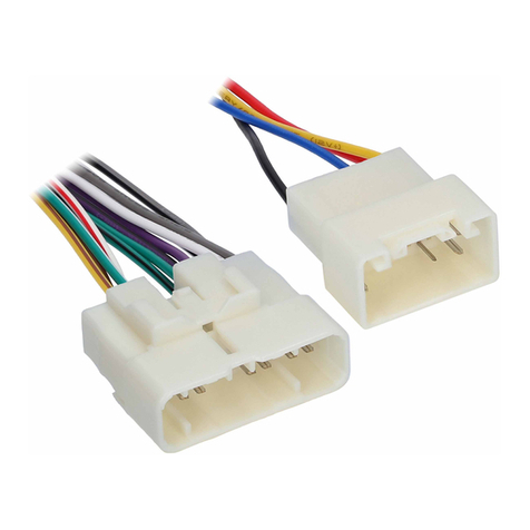
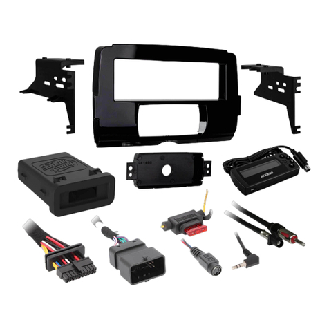
• Connect the 5843 harness into the interface, and then to the wiring harness in the vehicle.
• Connect the 16-pin harness with stripped leads into the interface.
• Connect the harness removed in step 6 of dash disassembly, back into the factory screen.
• Connect the harness removed in step 5 of dash disassembly, to the
radio trim panel.
Note:
If retaining steering wheel controls, ensure the jack/wire is connected before proceeding
onto the next step.
INITIALIZING THE INTERFACE
INSTALLING THE INTERFACE
For the steps below, the Red L.E.D. (located inside the interface, next to the potentiometer) can only be seen
while active. The interface does not need to be opened to see the L.E.D.
• Turn the key (or push-to-start button) to the ignition position, the L.E.D. will turn on.
• Within a minute, the L.E.D. will turn off for a couple seconds, then flash slowly (up to (18) times,
indicating which radio is connected to the interface), and then turn off. Pay close attention as to how
many slow flashes there are. This will help in troubleshooting, if need be. Refer to the L.E.D. feedback
section for more information.
• Within a few seconds the L.E.D. will turn on, and the radio will turn off.
• Within a minute the L.E.D. will turn off, and the radio will come back on, indicating the initialization
process is successful.
Note:
If the radio does not come back on within a minute, the interface is not communicating to the
vehicle. Turn the key off, check all connections, and then try again. The interface may need to be
reset at this point.
