Metrix CX 1651 User manual

Calibrateur multifonctions CX 1651
CX 1651
北京海洋兴业科技股份有限公司(证券代码:839145)
电话:010-62176775
网址:www.hyxyyq.com

Calibrateur multifonctions CX 1651
Manuel de l'utilisateur 93
Control of the calibrator......................................................................................................106
Selection of function.....................................................................................................................106
Setting the value of output signal................................................................................................106
Setting relative deviation.............................................................................................................108
Change of value by factor of ten.................................................................................................109
Connection / disconnection of output terminals........................................................................109
Setting the frequency....................................................................................................................110
Generation of calibrated voltage.................................................................................................111
Generation of calibrated current................................................................................................113
Generation of non-harmonic shapes...........................................................................................114
Simulation of resistance and capacitance...................................................................................115
Generation of electric power and energy...................................................................................118
Generation of frequency..............................................................................................................123
Simulation of temperature sensors.............................................................................................126
Multimeter............................................................................................................................ 130
Basic menu ....................................................................................................................................130
Function selection.........................................................................................................................131
Setting the measurement range...................................................................................................131
Units of measurement ..................................................................................................................132
Use of calculation formula...........................................................................................................133
Setting function parameters........................................................................................................133
Start of measurement...................................................................................................................134
Zero function.................................................................................................................................134
Simultaneous functions................................................................................................................136
Tester....................................................................................................................................138
Basic menu ....................................................................................................................................138
Execution of test program ...........................................................................................................138
Programming the test...................................................................................................................139
Setting the type of signals and the number of steps...................................................................................140
Setting the numeric values of the test ........................................................................................................140
Setting the relays .......................................................................................................................................141
Setup menu ..........................................................................................................................141
Error messages .................................................................................................................... 145
Calibrator’s maintenance....................................................................................................147
Performance Verification test ............................................................................................. 149
System control...................................................................................................................... 157
IEEE-488 bus properties..............................................................................................................157
RS232 bus properties ...................................................................................................................157
北京海洋兴业科技股份有限公司(证券代码:839145)
电话:010-62176775
网址:www.hyxyyq.com

Calibrateur multifonctions CX 1651
94 Manuel de l'utilisateur
Command syntax ......................................................................................................................... 158
Examples of use ...................................................................................................................163
Calibration of measurement instruments ................................................................................. 163
Multimeters................................................................................................................................................163
Counters and oscilloscopes........................................................................................................................165
Measurement................................................................................................................................ 166
Voltage, current and frequency..................................................................................................................166
Measurement of resistance or temperature using resistance temperature sensors......................................167
Measurement of temperature using thermocouples....................................................................................168
Strain gauge sensors for non-electrical values ...........................................................................................168
Testing of regulation and measurement sets and evaluation units......................................... 170
Use of Opt. 140-41 cable adapter ..............................................................................................................170
Use of Option 40/60 cable adapter ............................................................................................................171
Use of Option 70........................................................................................................................................171
Examples of tests.......................................................................................................................................171
Testing.......................................................................................................................................................173
Specification.........................................................................................................................173
Accessories............................................................................................................................181
北京海洋兴业科技股份有限公司(证券代码:839145)
电话:010-62176775
网址:www.hyxyyq.com

Calibrateur multifonctions CX 1651
Manuel de l'utilisateur 95
Basic Information
CX 1651 Multifunction Calibrator is a multifunction calibrator-tester, to be used primarily as a standard
for calibration laboratories. It can be used for calibration of any measuring instrument which measures voltage,
current, resistance, capacitance and frequency. It generates fixed non-harmonic signals to allow calibration
of measuring instruments using signals with non-zero harmonic distortion. Frequency, amplitude and duty cycle
of output signal can be adjusted. CX 1651 Multifunction Calibrator is also suitable for basic calibration
of oscilloscopes.
The calibrator includes a function which simulates resistance and thermocouple temperature sensors and
a built-in multimeter, which can be used simultaneously. Transducers of various types, regulators and sensing
units can be therefore checked without the need for additional measuring instruments.
Programmable functions of the calibrator, when used as a tester, include programming of a 10-step testing
procedure, which completes automatically and displays a PASS/FAIL information in the end. This feature is
linked to an independent relay output, which allows the control of other equipment.
Basic features of the calibrator include: generation of calibrated DC and AC voltage in the range of 0
µV to 1000 V, DC and AC current in the range of 0 µA to 20 A (50 µA to 1000 A when using a 50-turn coil).
Maximum precision of the calibrator is 0.0035 % for DC voltage, 0.03 % for AC voltage, 0.013 % for DC
current and 0.055 % for AC current. Maximum frequency range is 20 Hz to 50 kHz. The calibrator can generate
periodic non-harmonic signal with defined duty cycle. This facilitates especially the checks of multimeters and
their accuracy when measuring non-harmonic DC signals.
The calibrator can also simulate a resistance or capacitance. Resistance range is 0 Ωto 50 MΩ;
capacitance range is 1 nF to 50 µF, the accuracy suits the calibration of common multimeters. Basic accuracy
of resistance ranges is 0.03 %. Basic accuracy of capacitance ranges is 0.5 %. The resistance can be used with
AC signals up to 300 Hz to 1 kHz, depending on set-up value.
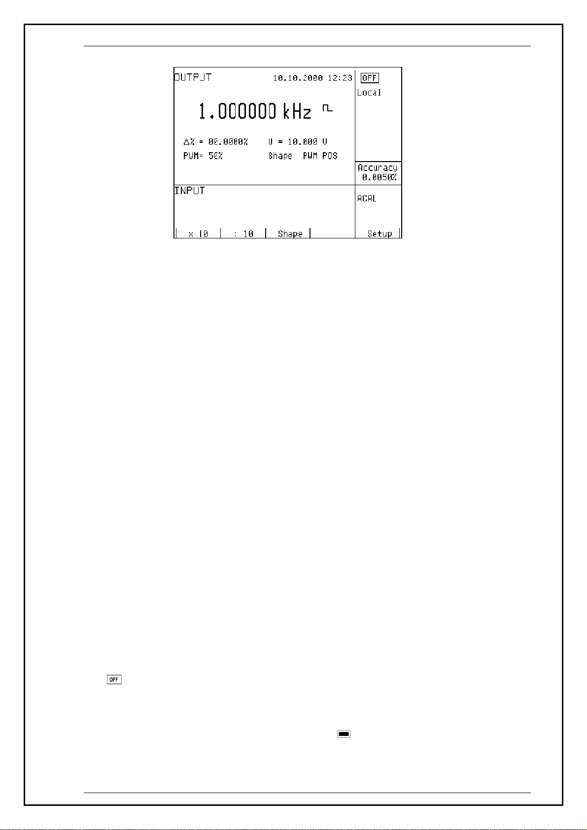
Frequency ranges of the calibrator can generate a squarewave signal with definable and calibrated duty
cycle and amplitude in the 1 mV to 10 V range and 0 to 10 kHz frequency range. Moreover, squarewave signal
with very steep rising edge can be generated up to 20 MHz. Frequency ranges can be used to calibrate the
corresponding frequency ranges of multimeters, as well as to calibrate the input sensitivity and time bases of
oscilloscopes.
Powermeter mode can be used to calibrate DC and AC single phase powermeters and energy meters.
Voltage range is up to 240 V and current range is up to 10 A, power factor range is -1 to +1 and the resolution is
1 % in the 40 Hz to 400 Hz frequency range. The voltage output can supply loads up to 30 mA, which allows the
calibration of mechanical powermeters.
Simulation of temperature sensors is yet another feature which can be used to calibrate thermometers
and heat sensing units. The calibrator allows the simulation of all common Pt and Ni resistance sensors and R, S,
B, J, T, E, K, N type thermocouples. Compensation of cold junction of thermocouple is achieved by entering
the respective temperature using the calibrator’s keyboard. The accuracy of simulated temperature sensors
depends on the value and type of sensor and ranges from 0.04 oC to 0.5 oC for resistance sensors and from
0.4 oC to 4.3 oC for thermocouples.
Internal multimeter with 20 mA, 20 mV, 200 mV and 10 V basic ranges and 0.01 % accuracy can be
used to measure normalized signals coming from transducers, external thermocouples or resistance sensors or to
measure pressure and force using strain gauge sensors.
The calibrator includes many other features which facilitate easy use. For example relative deviation from set
value of the output, currently displayed uncertainty of the output signal, calibration and testing procedures etc.
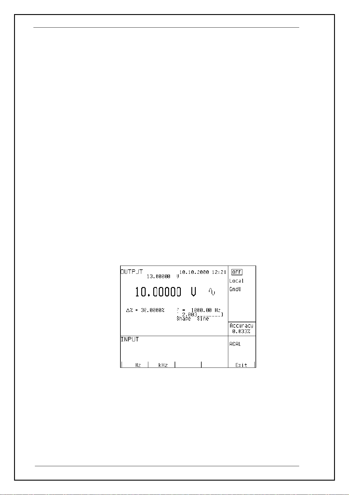
The concept of calibrator control and indication of its status is based on flat luminiscent display, which provides
all necessary information. The calibrator is controlled by opening menus on the display and selection from
menus. Frequently used functions are assigned direct-control keys. The calibrator comes with standard GPIB bus
and RS-232 serial line, which allow the calibrator to be controlled from a PC.
The calibrator can easily fit within calibration systems featuring MBASE/WinQbase software support.
北京海洋兴业科技股份有限公司(证券代码:839145)
电话:010-62176775
网址:www.hyxyyq.com

Calibrateur multifonctions CX 1651
96 Manuel de l'utilisateur
ATTENTION !
The calibrator generates life-threatening high voltage.
The calibrator can only be used in line with this
Manual.
北京海洋兴业科技股份有限公司(证券代码:839145)
电话:010-62176775
网址:www.hyxyyq.com

Calibrateur multifonctions CX 1651
Manuel de l'utilisateur 97
Preparation for operation
Inspecting package contents, selecting the installation location
Basic package includes the following items:
•Multifunction calibrator
• Power cord
• Spare fuse T4L250/T, T8L250/T
• Operation manual.
• Test report
• Test cable 1000V/20 A 2 pcs
• Cable adapter Option 40
• Cable adapter Option 60
• Cable adapter Option 70
• RS 232 cable
The calibrator should be powered by 230/115 V – 50/60 Hz mains. It is a laboratory instrument whose
parameters are guaranteed at 23±2 oC. Before powering on the instruments, place it on a level surface. Do not
cover the vents at the bottom side and the fan opening at the rear panel.
Power-on
• Before connecting the calibrator to the mains, check the position of the mains voltage selector located at the
rear panel.
• Plug one end of the power cord into the connector located at the rear panel and connect the other end of the
power cord into a wall outlet.
• Switch on the mains switch located at the rear panel. Flat display is lit.
• The calibrator performs internal hardware checks for 5 seconds.
• After the tests conclude, the calibrator resets to its reference state, i.e. the following parameters are set:
Function DC voltage
Range 20 V
Set value 10 V
Output terminals OFF
GPIB address of the calibrator is factory-preset to 2. This value is valid until the user changes it.
Note. The calibrator resets to its reference status in case of power switching off and reconnection.
Warm-up time
The calibrator works after it is switched on and the initial checks complete. Specified parameters are only
guaranteed after the instrument warms up for 60 minutes. During this period, the instrument cannot be calibrated.
The display shows “cannot access the calibration” message if calibration is attempted during this period.
北京海洋兴业科技股份有限公司(证券代码:839145)
电话:010-62176775
网址:www.hyxyyq.com

Calibrateur multifonctions CX 1651
98 Manuel de l'utilisateur
Replacement of fuse
The calibrator includes a fuse located in the mains connector at the rear panel. Replace the fuse as follows:
•Switch off the calibrator
• Remove the end of power cord from the mains connector at the rear panel.
• Insert the blade of a flat screwdriver into the opening cut in the mains voltage selector and pull out the fuse
holder.
• Remove the fuse and replace it with new fuse of the same rating.
Safety precautions
The instrument has been designed in Safety Class I according to EN 61010-1. The design reflects the
requirements of A2 amendment of the standard.
Safety is ensured by the design and by the use of specific component types.
The manufacturer is not liable for the damage caused by modification of the construction or replacement of parts
with non-original ones.
Safety symbols used on the equipment
Warning, reference to the documentation
Warning - risk of electric shock
Danger - high voltage
北京海洋兴业科技股份有限公司(证券代码:839145)
电话:010-62176775
网址:www.hyxyyq.com

Calibrateur multifonctions CX 1651
Manuel de l'utilisateur 99
Description of controls
Front panel
The front panel of the calibrator includes a flat luminiscent display, control buttons and output terminals. The
following picture shows the control part of the front panel.
1 Display buttons
There are five buttons below the display, whose meaning changes depending on the contents of the display.
These buttons usually call-up the MENU, allow range change, step, logging of values etc.
2 Cursor buttons
Using these buttons, the cursor can be controlled within allowed limits on the display. The keyboard includes two
buttons (<, >) which allow the cursor to be set to the required position at the display. The cursor can be moved to
the left or right. These buttons are usually used to step through the options and to move from one option to
another or between the menu levels. Numeric values can be set in some control modes as well. In these cases, the
buttons marked (∧, ∨) allow the user to increase or decrease the number at the cursor button.
The central button is used to confirm the selection (ENTER), or to SELECT from the menu.
3 Potentiometer
The potentiometer integrates several functions. By turning the knob to the left or right, the user can:
• step through the options
• enter numeric values
3 5
1 2 4 6 7
北京海洋兴业科技股份有限公司(证券代码:839145)
电话:010-62176775
网址:www.hyxyyq.com

Calibrateur multifonctions CX 1651
100 Manuel de l'utilisateur
The function of the potentiometer can usually be performed by the cursor buttons. The central button is used to
confirm the selection (ENTER).
4 Numeric keyboard
The keyboard allows the entry of numeric values on the display. The central button is used to confirm the
selection (ENTER). CANCEL button can be used to cancel the entry.
5 Function buttons
Function buttons can be used to call-up the functions of the calibrator directly. The following buttons are
provided:
function button
DC voltage U / DC
AC voltage U / AC
DC current I / DC
AC current I / AC
resistance / capacitance R – C
power / energy P – E
frequency F
internal multimeter METER
simulation of temperature sensors T
After the function mode is changed, the parameters of the respective function are restored. If the respective
function was never used, the calibrator resets to its reference values. Reference values for individual functions are
listed below.
function value parameters
DC voltage 10V - -
AC voltage 10 V f = 1000 Hz
DC current 100 mA - -
AC current 100 mA f = 1000 Hz
resistance 100 kΩ
capacitance 1 µF
power 100 W f = 100 Hz *1
energy
frequency 1000 Hz U = 1 Vsym
multimeter 10 V DC voltage
simulation of temperature sensors 100 oC Pt 100/1.385, ITS90
cold junction temperature of TC sensors 23 oC R
*1 U = 100 V, I = 1 A, PF(power factor) = 1 LA, active power is displayed in Watts
北京海洋兴业科技股份有限公司(证券代码:839145)
电话:010-62176775
网址:www.hyxyyq.com

Calibrateur multifonctions CX 1651
Manuel de l'utilisateur 101
6 Output / input terminals buttons
OUTPUT button is used to connect the output signal of the calibrator to the output terminals. The connection is
confirmed by red LED and a symbol at the display.
METER button can be used to connect the input terminals to the internal multimeter. The connection is
confirmed by green LED.
7 Output / input terminals
Output signal of the calibrator is connected to the output terminals. Current ranges are connected to +I / -I
terminals, frequency output is connected to FREQ terminal. All other functions (voltage, resistance, capacitance)
are connected to Hi / Lo terminals.
GND terminal is connected to the chassis of the calibrator. It is connected to the ground terminal of the mains
plug. Using the SETUP MENU of the calibrator, the output terminals of the calibrator can be grounded as well.
Grounding is done internally by connecting Lo and GND terminals using a relay. This circuit design is suitable
for most calibrations, when the object (multimeter) being calibrated is floating.
AUXILIARY connector creates input of internal multimeter. It includes a limited range of output signals of the
calibrator as well. The layout of individual pins and their meanings are listed in the following table.
Auxiliary connector can be used with one of cable adapters Opt. 40, 60, 70, Opt. 140-41. Calibrator can
recognize which type of adapter is connected and displays the information on front panel display.
北京海洋兴业科技股份有限公司(证券代码:839145)
电话:010-62176775
网址:www.hyxyyq.com

Calibrateur multifonctions CX 1651
102 Manuel de l'utilisateur
pin label signal limitation
1 L common terminal of multimeter input
2 INP input terminal of multimeter for voltage/current ranges Umax.=25 Vpp, Imax.=25 mA
3 -U low output terminal for DC voltage range
4 +U high output terminal for DC voltage range Umax.=20 Vss
5 -I low output terminal for DC current range
6 +I high output terminal for DC current range Imax.=25 mA
7 NG1 sort function output, contact 1 of relay Umax.=50Vpp, Imax.=100 mA
8 NG2 sort function output, contact 2 of relay Umax.=50Vpp, Imax.=100 mA
9 PTLI resistance temperature sensor input terminal Li Umax.= 10Vpp. R<2 kΩ
10 PTHI resistance temperature sensor input terminal Hi Umax.= 10Vpp. R<2 kΩ
11 PTLU resistance temperature sensor input terminal Lu
input terminal L on ranges 20, 200, 2000 mV
Umax.= 10Vpp. R<2 kΩ
12 PTHU resistance temperature sensor input terminal Hu
input terminal H on ranges 20, 200, 2000 mV
Umax.= 10Vpp. R<2 kΩ
13 TEST1 identification terminal of actually used adapter
14 TEST2 identification terminal of actually used adapter
15 NC not used
16 NC not used
17 0 identification terminal of actually used adapter
18 0 identification terminal of actually used adapter
19 NC not used
20 SIMLI RC simulator output, current terminal Lie Umax.= 10Vpp, Imax.=40mA
21 SIMHI RC simulator output, current terminal Hi Umax.= 10Vpp, Imax.=40mA
22 SIMLU RC simulator output, voltage terminal Hi Umax.= 10Vpp, Imax.=40mA
23 SIMHU RC simulator output, voltage terminal Hu Umax.= 10Vpp, Imax.=40mA
24 NC not used
25 NC not used
Functional inputs and outputs present at the connector can be best utilized using supplied cable adapters.
LCD display shows all information provided by the calibrator, e.g. set parameters of the signal, error messages,
setup information. The display is divided to several information sections.
北京海洋兴业科技股份有限公司(证券代码:839145)
电话:010-62176775
网址:www.hyxyyq.com

Calibrateur multifonctions CX 1651
Manuel de l'utilisateur 103
8 Display
1a 1b 1c 1d 1e 2a 3 2b 1g 1f
The display is divided to three horizontal sections:
4. OUTPUT section
This section displays the set-up values of generated signals and the data related to the calibrator status. The
section includes the following types of data:
a) Information line
• designation of display section: OUTPUT
• error messages. The messages appear when an attempt is made to set up an invalid state of the
calibrator, if analogue circuits of the calibrator are overloaded or if a communication error occurs
when the calibrator is controlled using GPIB bus.
• real date and time, if its display is set-up in the setup menu.
b) Auxiliary data
This line displays the total value of output signal if a non-zero relative deviation is set.
c) Main data
This line displays the main data of the output signal and the unit of measurement (using double size
signs). The line also includes two symbols (▼▲) to define the actual position of the cursor during
adjustment of the value. <, > buttons can be used to move the cursor and ∧, ∨buttons to change the
value. (The value can be also changed using the potentiometer).
d) Monitoring line
This line displays the numbers entered using the numeric keyboard when the main data are set using the
numeric keyboard. The information allows the entered information to be checked.
e) Minor data
There are two lines displaying the minor data of the output signal, especially:
• set relative deviation from main set value in %
• frequency (for DC voltage, current, power, energy functions)
• set value of current, voltage or power factor (phase) for power, energy functions
北京海洋兴业科技股份有限公司(证券代码:839145)
电话:010-62176775
网址:www.hyxyyq.com

Calibrateur multifonctions CX 1651
104 Manuel de l'utilisateur
• value of R0 resistance and the type of resistance temperature sensor
• cold junction temperature of TC sensors and the selected type of TC sensor
• value of amplitude and shape type for frequency function
f) Information section
The information section located in the right part of the display displays additional information related to
the selected function:
• symbol of connected or disconnected output terminals.
At the same time, a LED located above the OUTPUT button is lit.
• information about remote/local control of the calibrator. If the calibrator is controlled remotely,
REM is displayed. If the calibrator is controlled locally using the keyboard, LOCAL is displayed.
• information about the use of 50-turn coil (COIL x50) at the current output of the calibrator, if this
feature is turned on using the SETUP menu.
• information about the type of connected cable adapter, if used
• information about the grounding method of output terminals: GND I, GND U as set up using the
setup menu.
g) Information about the uncertainty of the output signal
This section displays the maximum error of the main value of the output signal. The value is calculated
using the main specification listed in the User’s Manual and it is displayed in %.
5. INPUT section
This section displays the values measured by the multimeter. The section includes following data:
a) Main value of measured signal
This line displays the measured value and the unit of measurement. If the input signals exceed the
permitted range, OVERFLOW is displayed.
b) Designation of selected function of the multimeter
Symbolic display of selected function of the multimeter: V DC, mA DC, mV DC, R 4W, Freq, T TC, T
RTD, SGS, ACAL.
6. Display buttons section
This line displays the symbolic descriptions which define the meaning of four related display buttons. The
respective meanings are as follows:
symbol button function note
x 10 increase set value 10 x
: 10 decrease set value 10 x
Shape selection of signal shape only for U, I, F functions
+/- reversed polarity of output voltage and current only for DC U, DC I functions
EXIT move up one level only for F, P-E functions
Calib. enter the calibration menu
SETUP enter the setup menu
TC type selection of thermocouple sensor type only for T function
RTD type selection of resistance temperature sensor type only for T function
f enter the frequency of the signal only for U, I function
MODE select the unit of measurement only for AC P-E function
北京海洋兴业科技股份有限公司(证券代码:839145)
电话:010-62176775
网址:www.hyxyyq.com

Calibrateur multifonctions CX 1651
Manuel de l'utilisateur 105
Rear panel
The rear panel of the calibrator includes ventilation holes, power cord socket with fuse, mains voltage selector,
mains switch, IEEE 488 connectors for connection to GPIB bus and type plate with serial number.
1 air inlet - forced ventilation
2 air outlet - forced ventilation
3 GPIB, RS-232 connectors
4 power cord socket with fuse, mains voltage selector, mains switch
5 type plate
5 1 2
4 3
北京海洋兴业科技股份有限公司(证券代码:839145)
电话:010-62176775
网址:www.hyxyyq.com

Calibrateur multifonctions CX 1651
106 Manuel de l'utilisateur
Control of the calibrator
Selection of function
After the power is switched on and the initial checks complete, the calibrator resets to its reference status, i.e. DC
voltage output with set value of 10 V and output terminals disconnected. Internal multimeter is switched off. The
status of the calibrator can be changed using the buttons located at the front panel in one of the following ways:
5. Change of function by pressing one of direct function buttons
After pressing one of the U, I, DC-AC, R-C, P-E, F, T, METER buttons, the calibrator switches to the desired
function mode and resets to the reference or to the most recently used parameter setting.
6. Connection /disconnection of output terminals
After pressing the OUTPUT button, the output terminals of the calibrator are connected/disconnected.
7. Connection /disconnection of multimeter
After pressing the INPUT button, the multimeter starts measuring the value present at the input terminals,
depending on the function mode of the multimeter. The measurement is only possible when any of Opt. 140-xx
adapters is connected to the AUXILIARY connector.
8. Entry to the setup menu
After pressing the SETUP button, options of the SETUP MENU appear on the display and the display buttons
allow the entry to the calibration mode (CALIB) or entry to the mode when the calibrator is used as a tester
(TESTER). Previous function is restored by pressing of EXIT display button.
Setting the value of output signal
All function modes allow several methods of setting the main value of the output signal:
Entry of the value using numeric keyboard
• use the numeric keyboard to select the desired value. After the first digit is entered, symbols of unit
of measurements are displayed above the display buttons. The monitor line displays the symbols
[ _ _ _ _ _ _ _ _ ].
• the same entry can be started by pressing the central cursor button
• after the entry is complete (the value is displayed on the monitor line), press the display button
below the desired unit of measurement (V, mV or µV in the example below)
• the value is copied to the main display and the monitor line disappears.
北京海洋兴业科技股份有限公司(证券代码:839145)
电话:010-62176775
网址:www.hyxyyq.com

Calibrateur multifonctions CX 1651
Manuel de l'utilisateur 107
Entry of the value using cursor buttons
• press <, >, ∧or ∨button. The display now includes cursor marks which point to the active digit.
• ∧ and ∨buttons can be used to change the active digit. <, >buttons can be used to change the
position of the cursor marks
• to get to the default screen, press EXIT button or keep pressing the center cursor button until there
is no [ _ _ _ _ _ _ _ ] under any value. All values can be set using the buttons or the potentiometer.
Entry of the value using the potentiometer
• press the potentiometer knob. The display now includes cursor marks which point to the active digit
• turn the knob to change the active digit
• press the potentiometer knob to change to the mode which allows to change the value of the active
digit. ←and →symbols are displayed above the active digit. Active digit can be changed by
turning the knob.
• turn the knob to change back to the mode which allows to change the position of the active digit.
• to get to the default screen, keep pressing the center cursor button until there is no [ _ _ _ _ _ _ _ ]
under any value, or press EXIT button. All values can be set using the buttons or the potentiometer.
Reverse polarity
In DC voltage and DC current modes, the polarity of the output value can be reversed by pressing +/- display
button. „ - “ symbol appears in front of the main data value.
北京海洋兴业科技股份有限公司(证券代码:839145)
电话:010-62176775
网址:www.hyxyyq.com

Calibrateur multifonctions CX 1651
108 Manuel de l'utilisateur
Setting relative deviation
All function modes of the calibrator except frequency mode allow a relative deviation of output value from the
main data to be set using a separate display. Relative deviation is displayed in the “minor data” section of the
display and is designated with „ ∆%= 00.0000 % “ symbol. The relative deviation can be entered using one of the
methods described above, e.g. using the numeric keyboard, cursor keys or the potentiometer.
Setting relative deviation using numeric keyboard
• keep pressing the center cursor button until [ _ _ _ _ _ _ _ ] symbols appear under the relative
deviation value in the “minor data” section of the display
• enter the desired deviation and confirm the value by pressing “ % “ display button or by pressing
ENTER on the numeric keyboard
• the auxiliary line below the main data on the display displays the total value of output signal
including the unit of measurement
• the value of the signal at output terminals is: the value indicated by the main display + ∆%.
Maximum relative deviation which can be entered is ±30.000 %.
The deviation can be positive or negative. If negative deviation is desired, press the display button labeled +/-. If
positive deviation is then desired, press “ +/- “ button again. The polarity of the relative deviation can be reversed
using the cursor buttons or the potentiometer as well.
Setting relative deviation using cursor keys
• keep pressing the center cursor button until [ _ _ _ _ _ _ _ ] symbols appear under the relative
deviation value
• press <, >, ∧or ∨button. The display now includes cursor marks which point to the active digit
• ∧ and ∨buttons can be used to change the active digit. <, >buttons can be used to change the
position of the cursor marks
• to get to the default screen, keep pressing the center cursor button until there is no [ _ _ _ _ _ _ _ ]
under any value, or press EXIT button. All values can be set using the buttons or the potentiometer..
北京海洋兴业科技股份有限公司(证券代码:839145)
电话:010-62176775
网址:www.hyxyyq.com

Calibrateur multifonctions CX 1651
Manuel de l'utilisateur 109
Setting relative deviation using potentiometer
• keep pressing the center cursor button until [ _ _ _ _ _ _ _ ] symbols appear under the relative
deviation value in the “minor data” section of the display
• press the potentiometer knob. The display now includes cursor marks which point to the active
digit. Turn the knob to change the value of the active digit
• press the potentiometer knob to change to the mode which allows to change the position of the
active digit. ←and →symbols are displayed above the active digit. The position of the active digit
can be changed by turning the knob.
• turn the knob to change back to the mode which allows to change the value of the active digit
• to get to the default screen, keep pressing the center cursor button until there is no [ _ _ _ _ _ _ _ ]
under any value, or press EXIT button. All values can be set using the buttons or the potentiometer.
If a non-zero relative deviation is set, the main data can be changed as well. The value of the output signal is
always recalculated. If a zero relative deviation is set, the “minor data” section is not displayed.
Change of value by factor of ten
All functions of the calibrator allow the increase of the output value by 10 or reduction of the output value by 10.
Such operation is equivalent to the change of internal range only in U, I, P-E modes. If the change results in
overflow or underflow of calibrator’s range, an error message appears:
Value too large ! if the resulting value is too large
Value too small ! if the resulting value is too small
Range change
• Press the display button labeled “ x10 “ if you want to increase the range, “ :10 “ to decrease the
range.
• The main value shown on the display is increased 10x (reduced 10x)
P-E function changes the current, not voltage, when the range is changed.
R-C function changes the set value 10x. The procedure, however, cannot be used to step the internal
resistance/capacitance ranges, which are not decimal.
T function also has other than decimal ranges and the change of set value 10x therefore does not correspond to
internal range change. Internal range change in this case depends on the temperature sensitivity of the
resistance/capacitance.
Connection / disconnection of output terminals
After switching on the output terminals are disconnected in all modes. Press the OUTPUT button to connect the
output signal to the terminals. Red LED above the OUTPUT button is lit and the information field on the display
shows the following symbol .
Press the OUTPUT button again to disconnect the output terminals. Red LED goes off and the information field
北京海洋兴业科技股份有限公司(证券代码:839145)
电话:010-62176775
网址:www.hyxyyq.com

Calibrateur multifonctions CX 1651
110 Manuel de l'utilisateur
on the display shows the following symbol .
During mode change, output terminals are always disconnected. Output terminals are disconnected also when
changing between voltage and current ranges or when changing between AC and DC ranges is performed.
If voltage over 100 V is set in the voltage mode, special algorithm must be followed to connect the output
terminals. The algorithm is described in the „Generation of calibrated voltage“ chapter of this Manual.
Setting the frequency
Frequency can only be selected in AC voltage (ACU) mode, AC current (ACI) mode , power (P-E) mode and
frequency (f) mode. In each mode the frequency has a slightly different meaning and the frequency is therefore
set in a different manner.
AC voltage (ACU), AC current (ACI)
Set value of frequency is included in the “minor data” section of the display in ACU, ACI, P-E modes.
Frequency change
• First select the AC voltage or AC current mode by pressing U (I), AC buttons or selecting the P-E
mode using the display. Frequency value „f = xxx.xx Hz“ appears in the “minor data” section of the
display. “ f “ symbol is displayed above one of the display buttons.
• After “ f “ display button is pressed, [ _ _ _ _ _ _ _ ] symbols appear below the frequency value.
Numeric keyboard can be used to enter the desired value. Press “ Hz “ or “ kHz “ to confirm the
value. The value can be set using the buttons or the potentiometer.
If too large or too small value is entered, the calibrator displays the maximum (minimum) value which is allowed
for the selected function.
Frequency (F)
Set value of frequency is the main data on the display and the main parameter of the signal. Main data can be set
by direct entry using the numeric keyboard, potentiometer or by changing the digit at the current cursor position.
The setting procedure is described in the “Setting the value of output signal”.
北京海洋兴业科技股份有限公司(证券代码:839145)
电话:010-62176775
网址:www.hyxyyq.com

Calibrateur multifonctions CX 1651
Manuel de l'utilisateur 111
If frequency larger or smaller than the calibrator’s range is entered, the calibrator displays an error message:
„Value is too large (small)“.
Generation of calibrated voltage
The multifunction calibrator provides calibrated DC and AC voltage. Output terminals for voltage ranges are
labeled “ Hi “ and “ Lo “ at the front panel. Depending on the setting of the calibrator, voltage up to 1000 Vef
can be present at the terminals .
DC voltage range is 0 to 1000 V.
AC voltage range is 100 µV to 1000 V.
Output voltage up to 20 V is available at AUXILIARY connector. It can be used only with cable adapter Opt.
140-41.
Control in the voltage mode
• Press “U” button on the calibrator and then select AC or DC mode by pressing “DC-AC” button. The display
shows the following data:
* main data of set voltage
* relative deviation
* uncertainty of output voltage
* frequency (when AC voltage is generated)
* total value of output voltage when non-zero relative deviation is set
• Set the desired value of voltage, including polarity when necessary, frequency and relative deviation. The
signal is yet not connected to the output terminals. The information section of the display shows the symbol
which informs about the disconnection of output terminals.
• Press OUTPUT button.
• Red LED is lit above the OUTPUT terminals to signal the connection of the signal to the output terminals;
the information section of the display shows the symbol .
北京海洋兴业科技股份有限公司(证券代码:839145)
电话:010-62176775
网址:www.hyxyyq.com
Other manuals for CX 1651
1
Table of contents
Other Metrix Test Equipment manuals

Metrix
Metrix MX 407 User manual

Metrix
Metrix OX 530 User manual

Metrix
Metrix OX 5042 User manual

Metrix
Metrix PX 110 User manual

Metrix
Metrix HI-903 User manual

Metrix
Metrix HX0074 User manual

Metrix
Metrix MX2040 User manual

Metrix
Metrix MTX 3252e-C User manual

Metrix
Metrix HI 803 Specification sheet

Metrix
Metrix DOX 2 Series User manual

Metrix
Metrix GX-1030 User manual

Metrix
Metrix HI-903 User manual

Metrix
Metrix MX 535 User manual

Metrix
Metrix MTX 162UE TX 162UE User manual

Metrix
Metrix TCX01 User manual

Metrix
Metrix DOX3104 User manual

Metrix
Metrix HandScope OX5022B User manual

Metrix
Metrix MX 407 User manual

Metrix
Metrix MTX 3352 User manual

Metrix
Metrix OX 832 User manual