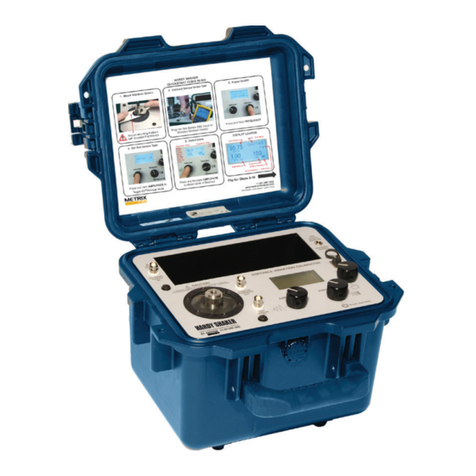
Metrix HI 803 Specification sheet

MODEL HI 803
Operaon and Installaon Manual
Doc# 0296-0018 • REV R (July 2017)
REF.
INPUT
MODE CURSOR
HELP SELECT
100 10K1K
FREQUENCY RANGE Hz
FREQUENCY
RUN
STORE
AMPLITUDE
ABC
7
PQR
6
MNO
5
JKL
4
GHI
9
DEF
8
STU
1
VWX
2
YZ -
3
0SPACE
PRINT PAPER
ADV
HI 803
TRANSDUCER TEST SET
50 mV/g
RS-232

Doc# 0296-0018 • REV R (July 2017) Page 2 of 61
TABLE of CONTENTS
Chapter 1 - Overview
A Brief Descripon of Chapter 1
About METRIX Manuals
Descripon
Capabilies
Amplitude Units
Frequency Units
Automac Calculaon
Phase
Automac Mass Load Correcon
Help Screens
Large Memory
Printer
Automac Date/Time
Baery Powered
ICP Accelerometers
Reference Accelerometer Output
Automac Power Management
Automac Monitoring and Supervisory Limits
Principles of Operaon
The Signal Generator
The Power Amplier
The Electrodynamic Amplier
The Reference Accelerometer
The Microcomputer
Baery Operaon
Special Handling and Storage
Lithium Baery
Chapter 2 - specicaons
A Brief Descripon of Chapter 2
Specicaons for the HI-803 TTS
Display
Calibraon
Measurement Uncertainty
Frequency Readout Accuracy
Amplitude Range
Transducer Sensivity Range
Reference Accelerometer Output
DI-103 & DI-103A Triaxial Mounted Specicaons
Sensivity
Frequency Range:
Power
Printer
Physical Dimensions
Environmental Specicaons
6
6
6
6
6
6
6
6
7
7
7
7
7
7
7
7
7
7
7
7
8
8
8
8
8
9
9
10
11
11
11
11
11
11
11
11
12
12
12
12
12
12
12
12
12

Doc# 0296-0018 • REV R (July 2017) Page 3 of 61
Chapter 3 - Installaon
A Brief Descripon of Chapter 3
Unpacking
Oponal Accessories
Mounng Bracket DI-103 (Triax) - Prt #0205-0057-01
Mounng Bracket DI-103A (Triax) - Prt #0205-0057-01
Kit
Kit
Cables for Sensivity Mode of Operaon
Kit
Kit
Installaon Procedures
TTS to TUT Cable Connector Pin Out Diagram (See Fig. 3-1)
Channel A
Channel B & C
Charge
Displacement Input
GND
+5V
Test Signal
Accelerometer - ICP Type
Accelerometer (Charge Type)
Triax Accelerometer (ICP Type)
Velocity Pickup
Piezoelectric Velocity Transducer
Displacement Eddy Current Proximity Probe
Voltage Powered Accelerometers
Chadwick-Helmuth Velocimeter #7310 Test Setup
Triaxial Accelerometer Installaon
Installaon of the Mounng Bracket and Cables
DI-103 Installaon for A & B Axes
DI-103 Installaon for the C-Axis Tests
DI-103A Installaon for A & B- Axes Tests
DI-103A Installaon for the C-Axis Tests
Installing Printer Paper
Transfer Test data from TTS to PC
Transfer Program
Data Format
Example of Download Data
Data Protocol
Chapter 4 - Calibraon
A Brief Descripon of Chapter 4
Required Test Equipment
TTS Calibraon Kit Prt. #0251-0009-01
Test Equipment Setup
Synthesizer Setup
Clear Memory Procedures
Calibraon Tests
Channel A Calibraon
Charge Channel Calibraon
Displacement DC Calibraon
REF Channel No Integ Calibraon
13
13
13
14
14
14
14
14
14
14
14
15
15
15
15
15
15
15
15
15
15
16
16
16
17
17
17
18
18
18
20
22
23
25
26
28
28
30
30
30
31
31
31
31
32
32
32
32
32
32
33
33

Doc# 0296-0018 • REV R (July 2017) Page 4 of 61
Frequency Calibraon Procedures
Unit Setup Procedures
Chapter 5 - operang procedures
A Brief Descripon of Chapter 5
Modes of Operaon
Baery Check
Setup Mode
Monitor Mode
Sensivity Mode
Bit Test Mode
Support Funcons
Help
Print
Up/Down Arrows
Power Message
Control and Indicators
Displacement Limits
Recommended Maximum Loads to be Placed on the TTS
Stud Torque Values
Types of Sensors
Displacement Sensor
Velocity Sensor
Accelerometer
Operang Procedures
Baery Check Mode
Setup Mode
Setup Screen #1
Setup Screen #2
Setup Screen #3
Monitor Mode
Monitor Mode Tesng
Sensivity Mode
Sensivity Test Setup
Sensivity Test Procedures Volt Type Transducer
Sensivity Mode Tesng for Displacement Type Transducer
Displacement Test Setup
Dynamic Sensivity Test
Stac Linearity Test
Sensivity Mode Phase Check
Operang Hints
General Vibraon Informaon
Relaonship in the Characteriscs of Vibraon Signals for Sine Waves
Relaonships of Sinusoidal Velocity, Acceleraon and Displacement
Crossover Frequencies for the TTS
Standard Checks for Transducers
Cable and Connector Checks
Quick Check Procedure
Built-In-Test (BIT) Test Mode
TTS Blink Range Summary
TTS CALIBRATION PROCEDURE CHECK-OFF SHEET
Test Transducer and Mounng Fixture Weight Guide
34
36
39
39
39
39
39
39
39
39
39
39
39
39
39
40
42
42
42
42
42
43
43
43
44
44
45
45
45
46
46
47
47
48
50
50
51
54
55
55
55
55
55
55
56
57
57
57
57
59
59

Doc# 0296-0018 • REV R (July 2017) Page 5 of 61
Table of Illustraons
CHAPTER 1 - OVERVIEW
FIG. 1-1 TRANSDUCER TEST SET (TTS) - BLOCK DIAGRAM
CHAPTER 3 - INSTALLATION
FIG. 3-1 CABLE CONNECTOR PIN OUT DIAGRAM
FIG. 3-2 ACCELEROMETER ICP TYPE
FIG. 3-3 ACCELEROMETER (CHARGE TYPE)
FIG. 3-4 TRIAX ACCELEROMETER (ICP TYPE)
FIG. 3-5 VELOCITY PICKUP
FIG. 3-6 PIEZOELECTRIC VELOCITY TRANSDUCER
FIG. 3-7 PROXIMITY PROBE
FIG. 3-8 VOLTAGE POWERED ACCELEROMETERS
FIG. 3-9 EXTERNALLY POWERED (FLOATING) ELECTRICAL SETUP
FIG. 3-10 TTS POWERED ELECTRICAL SETUP USING A SPECIAL CIRCUIT
(CONVERTS + TO -) LOCATED IN HOOKUP CABLE PRT. #0215-0102-01
FIG. 3-11 INSTALLATION OF MOUNTING BRACKET FOR AXIS A & B
FIG. 3-12 TOP PANEL/INPUT CONNECTOR
FIG. 3-13 ACCELEROMETER CONNECTOR PIN OUT DIAGRAM
FIG. 3-14 DI-103 A-AXIS POSITION WITH A ARROW POINTING DOWN
FIG. 3-15 DI-103 B-AXIS POSITION WITH B ARROW POINTING DOWN
FIG. 3-16 DI-103 INSTALLATION FOR C AXIS TEST
FIG. 3-17 DI-103A A-AXIS POSITION WITH A ARROW POINTING DOWN
FIG. 3-18 DI-103A B-AXIS POSITION WITH B ARROW POINTING DOWN
FIG. 3-19 DI-103A INSTALLATION FOR C-AXIS TEST
FIG. 3-20 PRINTER PAPER INSTALLATION
FIG. 3-21 HARDWARE OPTIONS FOR TTS AND PC CONNECTIONS
FIG. 3-22 SELECT COM PORT
FIG. 3-23 BROWSE TO FOLDER FOR SAVING DATA
CHAPTER 4 - CALIBRATION
FIG. 4-1 TTS INPUT TEST CABLE PRT. #0215-0095-01 WIRING DIAGRAM
FIG. 4-2 ADJUSTING THE REFERENCE OUTPUT (R113)
CHAPTER 5 - OPERATING PROCEDURES
FIG. 5-1 TTS CONTROLS, INDICATORS AND CONNECTORS
FIG. 5-2 BATTERY CHECK MODE SCREEN
FIG. 5-3 SETUP MODE SCREEN #1
FIG. 5-4 SETUP MODE SCREEN #2
FIG. 5-5 SETUP MODE SCREEN #3
FIG. 5-6 MONITOR MODE SCREEN
FIG. 5-7 SENSITIVITY MODE SCREEN
FIG. 5-8 SENSITIVITY TEST 1 SCREEN A
FIG. 5-9 DISPLACEMENT INTERIM SCREEN
FIG. 5-10 DISPLACEMENT PROBE MOUNTING FIXTURE WITH DIAL MICROMETER
FIG. 5-11 SENSITIVITY RESPONSE VARIANCES
FIG. 5-12 TYPICAL EDDY CURRENT PROBE PERFORMANCE
6
9
13
15
15
16
16
16
17
17
17
18
18
19
20
20
21
22
23
24
25
26
27
28
29
29
31
31
37
39
40
43
44
44
44
46
47
49
50
51
53
53

Doc# 0296-0018 • REV R (July 2017) Page 6 of 61
CHAPTER 1 - OVERVIEW
A Brief Descripon of Chapter 1
This manual provides the user and service personnel with a descripon of the specicaons, installa-
on, setup, conguraon, operaon, communicaon, maintenance, and troubleshoong procedures
for the METRIX Instruments HI 803 Transducer Test Set (TTS). The HI 803 TTS is a totally self-contained
baery powered vibraon transducer tester. The TTS can be used in the eld or in the laboratory. The
TTS tests and veries the performance of most vibraon transducers including accelerometers, velocity
pickups and displacement probes. The TTS is also used to troubleshoot vibraon monitoring systems or
vibraon analyzers including cabling and associated system alarms and other instrumentaon.
About METRIX Manuals
Every METRIX Installaon and Operaon manual is organized into easily referenced chapters, that are
almost always the same:
• Chapter 1 - Provides an introducon to the instrument and an Overview of the equipment
and its capabilies.
• Chapter 2 - Provides a complete list of Specicaons.
• Chapter 3 - Contains informaon needed to Install the HI 803 TTS. (both standard and
oponal equipment)
• Chapter 4 - Provides all Calibraon instrucons.
• Chapter 5 - Pertains to the Operang Procedures of the HI 803 TTS.
METRIX Instruments hopes that this manual meets your needs for informaon and operaon. All cor-
recons or suggesons for improvements of this manual are welcome and can be sent to the Technical
Publicaons Department or Customer Support Department at METRIX Instruments Inc.
Descripon
The HI 803 TTS performs the following primary funcons:
1. Vibraon Generator “Shaker” - The vibraon generator is used to vibrate or “shake” the Transducer-
Under-Test (TUT). The frequency and amplitude of the applied vibraon are selectable and digitally
displayed. Operaon control is maintained and supervised by a microcomputer. A highly accurate refer-
ence accelerometer, which is traceable to the Naon Instute of Standards (NIST), is used to provide the
measurement signal, ensuring high accuracy of the displayed frequency and amplitude levels.
2. Automacally Calculates Transducer Sensivies - Internal elec- tronics provide the necessary signal
condioning and drive current for most transducers. By measuring the output signal of the TUT as it
is vibrated, and comparing it with an internal reference signal, the sensivity (signal out per unit of
moon) of the transducer is automacally calculated. This is calculated sensivity can then be used to
determine whether the TUT is within the transducer manufacturer’s specicaons. A thermal printer is
built in to the TTS to provide hard copy printouts of the test parameters and test results.
Capabilies
Amplitude Units
Vibraon amplitude units are selectable and displayed in acceleraon, velocity or
displacement. The units are also selectable in English or Metric.
Frequency Units
Vibraon frequency is displayed in hertz (Hz). Ranges are user selectable in 3-100 Hz, 100-
1000 Hz and 1000-10,000 Hz, with front panel selecons for 100, 1K and 10K respecvely.
Automac Calculaon
Sensivity calculaons (mV/engineering unit or pc/engineering unit) are automacally per-
formed using a microcomputer.

Doc# 0296-0018 • REV R (July 2017) Page 7 of 61
Capabilies (connued)
Phase
During sensivity calculaon when the transducer selected is an acelerometer, the unit
displays the phase of the “transducer under test” relave to the internal reference acceler-
ometer.
Automac Mass Load Correcon
A special algorithm is used to automacally adjust measurements and calculaons to com-
pensate for the mass load of the transducer under test.
Help Screens
Help screens are provided during operaon to assist the operator.
Large Memory
Test parameters, test results and other test data can be stored in memory for future down
load via the printer. Informaon will be retained even though the TTS is turned o.
Printer
The TTS features a built-in thermal printer, which is used to hard copy data stored in memory.
Automac Date/ Time
A built-in real me clock displays date/me and automacally stamps hard copy print outs.
Baery Powered
Power is provided by two gel cell type baeries. The two baeries are charged via two built-
in charging systems that use a 110 VAC 50/60 Hz source. The user can use the TTS while the
baeries are being charged. 220 VAC is oponal.
ICP Accelerometers
Selectable current sources (.5 mA, 2 mA, 2.5 mA, 4 mA, 4.5 mA, 6 mA) are provided to power
ICP accelerometers.
Reference Accelerometer Output
A 50 mV/g, low impedance ( ~ 100 Ohms) reference accelerometer output signal is provided.
Automac Power Management
A power management and supervisory system is used to opmize power consumpon,
increasing the me between required charging. The instrument will automacally
turn o at the lowest acceptable voltage to ensure the baeries are not subjected to deep
discharge which can greatly reduce their operaonal life.
Automac Monitoring and Supervisory Limits
1. Warning - When test amplitude and/or frequency are out of acceptable ranges, the
operator is warned of the condion with ashing displays.
2. Shutdown - to prevent damage to the shaker, the TTS is automacally shut down when
maximum acceptable displacement limits are exceeded (approximately .125 inch P-P dis-
placement).
Principles of Operaon
The HI 803 Transducer Test Set is comprised of a Signal Generator, Power Amplier, Electro
dynamic Vibrator, Reference Accelerometer, Digital Voltmeter, Microcomputer and Digital
Indicator.
Doc# 0296-0018 • REV R (July 2017) Page 8 of 61
Capabilies (connued)
The Signal Generator
The signal generator produces a variable frequency sine wave which becomes the source of
the driving signal to produce the vibraon at the shaker head. The amplitude of this sine
wave signal is controlled by the front panel AMPLITUDE dial controller. The frequency is also
con trolled by the front panel FREQUENCY dial controller.
The Power Amplier
The power amplier is designed to provide the current required to drive the coil in the Elec-
trodynamic vibrator through an impedance matching circuit. The frequency and amplitude
of the shaker are controlled by and are proporonal to the frequency and amplitude of the
oscillator signal applied to the amplier input.
The Electrodynamic Amplier
The electrodynamic vibrator funcons by means of the interacon between the magnec
eld in the air gap and the oscillang current owing in the moving coil. This current gener-
ates a force at right angles to the liens of ux in the air gap and to the conductor carrying
the current. This force is proporonal to the product of the instanta- neous current and the
magnec ux density.
The Reference Accelerometer
The reference accelerometer is used to measure and set the level of vibraon at the shaker
head (which is the mechanical interface to the test transducer) for calibraon. The reference
accelerometer is an integral part of the shaker head. It’s sensing element is a ferroelectric
ceramic crystal that outputs a voltage proporonal to compression and extracon forces
imposed by a precise mass that is xed to the crystal assembly. This signal is condioned and
factory calibrate to 50 mV/g. A calibraon “standard” is maintained that is used to calibrate
the TTS and provide NIST traceability.
The vibraon levels can be read in English or Metric units as set by the setup program. Fre-
quency can be read in Hz.
The Microcomputer
The microcomputer manages the operaon of the TTS by interpreng external commands
entered from the front panel keys, monitoring operang parameters, measuring the built-in
reference accelerometer and the transducer under test, performing calculaons and driving
the display and printer. A signicant benet in having a microcomputer is its ability to run self
tests to insure the TTS is funconing properly.

Doc# 0296-0018 • REV R (July 2017) Page 9 of 61
FIG. 1-1 TRANSDUCER TEST SET (TTS) - BLOCK DIAGRAM
Baery Operaon
The TTS can be operated using an AC line power source or from its internal
rechargeable baeries. No switching is necessary since AC line power is always connect to
a built-in baery charger thereby providing a charge whenever connected to power. Maxi-
mum charge rate is achieved when the TTS is o.
Baery power for the TTS is supplied by two (2) sealed solid gel rechargeable baeries. The
baeries are designed for connuous charging without damage. Baeries should be kept
fully charged. Under nor- mal operaon, the TTS will operate in excess of 4 hours with fully
charged baeries.
Charge life is directly dependent on the power used which is established by the test require-
ments. When tesng requires high force be supplied to drive the test transducer (due to
heavy xturing or transducer size and/or due to high test levels) the charge life will be
shortened.
CAUTION A COMPLETE DISCHARGE CAN CAUSE BATTERY FAILURE.
A protecon circuit switches the TTS o automacally. When this occurs, the TTS must be
connected to AC power to acvate its charger right away. Under normal condions baeries
will obtain a full charge aer (8) hours charge me. If deep discharge occurs, one or more
days may be required to reach full charge.
Special Handling and Storage
The internal baeries are sealed and should provide long term service under normal operat-
ing condions. They are securely mounted heavy duty brackets so that no damage can occur
from shipping or normal transportaon. No special handling should be required.
TUT
AMPLIFIER
ASSEMBLY
Ref Accel
Amplifier
Assembly
Micro
Computer
and
Keyboard
DISPLAY
Sine
Generator
Freq
Ampl Adjust
Power
Amplifier
Assy
Electrodynamic
Shaker
PRINTER
CHARGER BATTERIES
TUT
Ref
Out

Doc# 0296-0018 • REV R (July 2017) Page 10 of 61
Lithium Baery
There is a Lithium baery that is used to maintain power to internal RAM which stores cali-
braon informaon for the TTS. This baery is designed to be funconal for 6 or 7 years. If it
fails, the TTS will display the following message upon start up, indicang a RAM problem:
RAM Error
If this message appears contact your local METRIX Representave right away. The TTS will
have to be returned to the factory to have a new lithium baery installed and the soware
reentered and funconally checked.

Doc# 0296-0018 • REV R (July 2017) Page 11 of 61
CHAPTER 2 - SPECIFICATIONS
A Brief Descripon of Chapter 2
Chapter 2 lists the specicaons for the HI 803 TTS. Specicaons are listed for the standard instrument
and for oponal equipment. The specicaons listed are designed to assist in the installaon, operaon
and troubleshoong of the instrument. All service personnel should be familiar with this secon before
aempng an installaon or repair of this instrument.
Specicaons for the HI-803 TTS
Display • High Contrast, Wide Viewing Angle
• Displays 5 x 7 dots plus cursor
• 20 characters x 4 lines
• Backlit Screen
Calibraon Traceable to NIST standard at 100 Hz from 2 to 5 g’s
Measurement • Acceleraon: 10 Hz to 2k Hz ± .3 dB
Uncertainty 2kHz to 10k Hz ± 1 dB
• Velocity: 10 Hz to 500 Hz ± .3 dB
500 Hz to 2kHz ± .5 dB
• Displacement: 20 Hz to 150 Hz ± .3 dB
150 Hz to 200 Hz ± .5 dB
• Triax: 30 Hz to 200 Hz ± .3 dB
Frequency Readout Accuracy 3 Hz to 10 kHz: .001% +- 1 count
Amplitude Range
• Maximum Acceleraon 10 g (100 m/sec2), PK
• Maximum Velocity 10 in/sec (254 mm/sec), PK
• Maximum Displacement 100 mils (2.54 mm), Pk-PK
• Generates the peak output acceleraons at the frequency ranges and loads as
follows:
Frequency
Range
0-100
Grams
100-240
Grams
250-500
Grams
500-750
Grams
10-100 Hz 10 g 4 g 2 g 1 g
100-1000 Hz 7 g 4 g 2 g 1 g
1-2 kHz 3 g 1.5 g 1 g n/a
1-10 kHz 3 g 1.5 g n/a n/a
NOTE: 1. Limited at lower frequencies to 0.1 inch (2.54mm) PK-PK displacement.
2. Care should be taken when mounng the test transducer and its support brackets to
reduce the possibility of resonance and decoupling (an-resonance).
3. For maximum output, baeries should be fully charged. Preferably, the TTS should be
powered by an external AC power source.

Doc# 0296-0018 • REV R (July 2017) Page 12 of 61
Transducer Sensivity Range
• Accelerometers:
ICP 5 mV/g - 200 mV/g
Charge 5 PC/g - 200 PC/g
• Velocity 5 mV/I.P.S. - 1 Volt/I.P.S.
• Displacement 30 mV/Mil - 300 mV/Mil
Reference Accelerometer Output
• Sensivity = 50 mV/g +- .15 dB @ 100 Hz
• Output Impedance = 100 Ohms nominal
DI-103 & DI-103A
Triaxial Mounted Specicaons
Sensivity +- 10% @ 100 Hz 10 mV/g
Frequency Range: Channel: A. +- 1 dB .2 - 2,000 Hz
Channel: B. +- 1 dB .2 - 2,000 Hz
Channel: C. +- 1 dB .2 - 5,000 Hz
Channel: C. +- 3 dB 1 - 10,000 Hz
Power • Baery Powered
• 115 VAC, 50/60 Hz charger (The instrument can be operated during charging)
• HI-803-220 VAC provides 220 VAC, 50 Hz charging capability
Printer • Thermal Type Printer
• Character Format 5 x 7 dot matrix
• Prinng Speed (Line/Sec) 0.9
• Paper Width 2.3”
Physical Dimensions
• Size - 11” (279.4 mm) Long x 7” (177.8 mm) Wide x 10” (254 mm) High
• Weight - 22.7 lbs (10.297 Kgs) 100 to 2700 F (-120 to +1320 C)
Environmental Specicaons
10° to 270° F (-120° to +132° C)

Doc# 0296-0018 • REV R (July 2017) Page 13 of 61
CHAPTER 3 - INSTALLATION
A Brief Descripon of Chapter 3
All informaon contained in Chapter 3 pertains to unpacking, cabling, interconnecng, conguraon
and installing the HI 803 TTS and Oponal Equipment. Alternaves to any procedures contained or
implied in this chapter are not recommended. It is very important that the user and service personnel
be familiar with the procedures contained in this chapter, before installing or operang the HI 803 TTS.
METRIX Instruments appreciates your business. Should you experience any problems installing this
equipment, contact your local or METRIX Instruments Inc., Customer Support for assistance.
Unpacking
Step 1. Before signing the packing slip, inspect the packing for damage of any kind.
Step 2. Report any damage to the carrier company immediately.
Step 3. Check to see that everything in the package matches the bill of lading. You should normally have:
• One Assembled HI 803 TTS Unit
• Power Cord (Prt. #6006-0008)
• Connector, Input to HI 803 (Prt. #2112-0007)
• Special Spanner Wrench (Prt. #0228-0072-01)
• Velocity Transducer Mounng Fixture (Prt. #0228- 0071-02) with screw (Prt. #2824-0135)
• Mounng 1/4-28 Stud Adapters:
1/4-28 Stud - - - - - - - - - - 0228-0070-01
10-32 UNF Stud - - - - - - - - 0228-0070-02
2-56 UNC Threaded Bushing - - 0228-0070-03
6-32 UNC Threaded Bushing - - 0228-0070-04
10-32 UNF Threaded Bushing - 0228-0070-05
• Screwdriver (Prt. #0228-0094-01)
• Operaon and Installaon Manual
NOTE: To ghten the stud adapters to the shaker head mounng hole, use the screwdriver provided
(Prt. #0228-0094-01) in the Accessories Kit. Using this screwdriver insures an adequate load on both
ends of the adapter. Do not apply more than 6 in/lbs of torque to prevent damaging or breaking the
adapter.
Step 4. Write down the Model and Serial number of the instrument. Store this informaon in a conve-
nient locaon for reference when contacng The METRIX Customer Support Department for parts or
service.

Doc# 0296-0018 • REV R (July 2017) Page 14 of 61
Oponal Accessories
Mounng Bracket DI-103 (Triax) - Prt #0205-0057-01
Mounng Bolt: Di-103 0205-0073-01
Mounng Screw: Bracket 2824-0137
Mounng Bracket DI-103A (Triax) - Prt #0205-0057-01
Mounng Bolt: Di-103 0205-0073-01
Mounng Screw: Bracket 2824-0137
Kit Displacement Probe Mounng Fixture,
1 1/4” Height 0251-0011-01
Kit Displacement Probe Mounng Fixture,
6” Height 0251-0019-01
Cables for Sensivity Mode of Operaon
• DI-103 Accel 0215-0088-01
• DI-108 Accel 0215-0088-01
• Micro Dot (10-32), ICP 0215-0086-01
• Micro Dot (10-32), ICP 0215-0087-01
• Chadwick-Helmuth
Velocimeter #7310 0215-0094-01
• 7993 Accel, ICP, 2 Pin 0215-0129-01
• 7993T Accel, ICP, 3 Pin 0215-0130-01
• Accel, ICP, BNC 0215-0131-01
• Accel, ICP, Alligator Clips 0215-0132-01
• Displacement, Alligator Clips 0215-0133-01
NOTE: Other TTS to TUT cables and connectors can be purchased from METRIX Instruments Inc. Con-
tact your local METRIX Dealer for informaon.
Kit Mounng Studs/Bushings
• 1/4-28 Stud 0228-0070-01
• 10-32 UNF Stud 0228-0070-02
• Metric M6 Stud 0228-0117-01
• 2-56 UNC Threaded Bushing 0228-0070-03
• 6-32 UNC Threaded Bushing 0228-0070-04
• 10-32 UNF Threaded Bushing 0228-0070-05
NOTE: For replacement baeries please contact your local METRIX Representave or the METRIX
Instruments Service Center.
Kit Spare Fuses (3)

Doc# 0296-0018 • REV R (July 2017) Page 15 of 61
Installaon Procedures
TTS to TUT Cable Connector
Pin Out Diagram (See Fig. 3- 1)
FIG. 3-1 CABLE CONNECTOR PIN OUT DIAGRAM
Channel A Input for all transducers that provide voltage outputs. Current can be selected by
menu for those transducers requiring current between.5 mA and 6 mA for power.
(See Fig. 3-2)
Channel B & C Use ONLY when tesng triax accelerometer (ICP type) (See Fig. 3-4)
Charge Used for charge accelerometers with a sensivity between 10 PC/g to 100 PC/g
(See Fig. 3-3)
Displacement Input For proximity type displacement transducer with voltage output between 0 and
-24 volts.
GND TTS signal ground
+5V Regulated +9V output at 6 mA maximum
Test Signal Test signal output for use with loop back test cable.
Accelerometer - ICP Type
FIG. 3-2 ACCELEROMETER ICP TYPE

Doc# 0296-0018 • REV R (July 2017) Page 16 of 61
Accelerometer (Charge Type)
FIG. 3-3 ACCELEROMETER (CHARGE TYPE)
Triax Accelerometer (ICP Type)
FIG. 3-4 TRIAX ACCELEROMETER (ICP TYPE)
Velocity Pickup
FIG. 3-5 VELOCITY PICKUP

Doc# 0296-0018 • REV R (July 2017) Page 17 of 61
Piezoelectric Velocity Transducer
Displacement Eddy Current Proximity Probe
Voltage Powered
Accelerometers
FIG. 3-6 PIEZOELECTRIC VELOCITY TRANSDUCER
FIG. 3-7 PROXIMITY PROBE
Some examples of Voltage Powered Accelerometers - Dynamic Instruments
DI-151, Wilcoxon 991B and Chadwick-Helmuth 4177B.
FIG. 3-8 VOLTAGE POWERED ACCELEROMETERS

Doc# 0296-0018 • REV R (July 2017) Page 18 of 61
Chadwick-Helmuth Velocimeter
#7310 Test Setup
The following informaon provides the electrical diagram for connect- ing the Chadwick-Helmuth Velo-
cimeter #7310 to the TTS. (See Figs. 3-9 & 3-10)
A
D
C
BVELOCIMETER
MODEL
#7310
TTS
4
2
GND
CHANNEL A
+V
GND
-V
GND
SIG
TTS INPUT PLUG
PRT. #2112-0007
-V = -5V TO -15V
+V = +5V TO +15V
@ 0.4 AMPS
EXTERNAL POWER
(FLOATING)
FIG. 3-9 EXTERNALLY POWERED (FLOATING) ELECTRICAL SETUP
A
D
C
BVELOCIMETER
MODEL
#7310
TTS
4
2
GND
CHANNEL A
GND
SIG
TTS INPUT PLUG
PRT. #2112-0007
3
+9V 6 4
1
5
7
8
+IN -OUT
LT1026
NC
GND
NC
+
+ 1 uF
.1 uF
23
-8.3V
+8.9V
FIG. 3-10 TTS POWERED ELECTRICAL SETUP USING A SPECIAL CIR- CUIT (CONVERTS + TO -) LOCATED IN
HOOKUP CABLE PRT. #0215- 0102-01
Triaxial Accelerometer Installaon
Installaon of the Mounng
Bracket and Cables
Step 1. ALWAYS use the Spanner Wrench (Prt. #0228-0072-01) to prevent damage to the Reference Ac-
celerometer when installing the mounng bracket or a test accelerometer. (See Fig. 3- 11)

Doc# 0296-0018 • REV R (July 2017) Page 19 of 61
FIG. 3-11 INSTALLATION OF MOUNTING BRACKET FOR AXIS A & B
Step 2. While holding the reference accelerometer steady with the spanner wrench, place the mounng
bracket (Prt. #0205- 0043-01) over the top of the reference accelerometer.
WARNING ALWAYS USE THE SPANNER WRENCH WHEN INSTALLING, REMOVING OR ADJUSTING THE
TRANSDUCERS OR MOUNTING BRACKET ON THE REFERENCE ACCELEROMETER.
Step 3. While sll holding the spanner wrench in place, use the allen wrench provided with the bracket
kit to screw the mounng bracket socket head screw into the reference accelerometer. (See Fig. 3-11)
Tighten the screw so that the bracket is snug against the reference accelerometer. If you want use a
torque wrench and torque to 18 inch pounds. Do not over torque the mounng screw. Overghtening
the mounng screw can cause bad readings.
Step 4. Install the connecng cable (Prt. # 0214-0088-01) between the Transducer under test (TUT) and
the input connector on the top panel. (See Fig. 3-12 & 3-13)
Triaxial Mounting Bracket
Mounting Bracket Screw
Spanner Wrench
Prt. #0228-072-01
Reference Accelerometer

Doc# 0296-0018 • REV R (July 2017) Page 20 of 61
REF.
INPUT
MODE CURSOR
HELP SELECT
100 10K1K
FREQUENCY RANGE Hz
FREQUENCY
RUN
STORE
AMPLITUDE
ABC
7
PQR
6
MNO
5
JKL
4
GHI
9
DEF
8
STU
1
VWX
2
YZ -
3
0SPACE
PRINT PAPER
ADV
HI 803
TRANSDUCER TEST SET
50 mV/g
RS-232
Input Connector
FIG. 3-12 TOP PANEL/INPUT CONNECTOR
A
DC
B
FIG. 3-13 ACCELEROMETER CONNECTOR PIN OUT DIAGRAM
Pin Funcon
ASIG A AXIS
B SIG B AXIS
C SIG C AXIS
DGROUND
TABLE 3-1: ACCELEROMETER CONNECTOR PIN AND FUNCTION
DI-103 Installaon for A & B Axes
Step 5. Posion the TUT for the A posion. (See Fig. 3-14)
NOTE: For Triaxial Mounted Specicaons go to Chapter 2, Triaxial Mounted Specicaons.
Table of contents
Other Metrix Test Equipment manuals

Metrix
Metrix HI-903 User manual

Metrix
Metrix MX 67 User manual

Metrix
Metrix MX2040 User manual

Metrix
Metrix GX-1030 User manual

Metrix
Metrix OX 6062-II User manual

Metrix
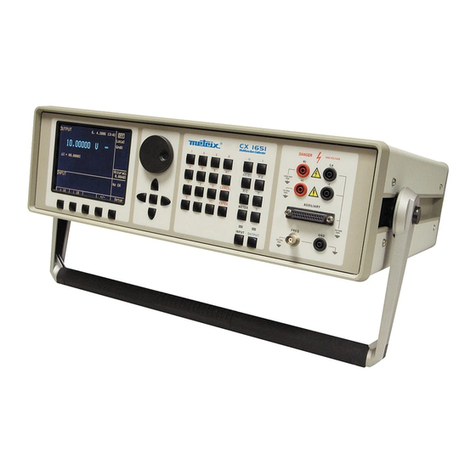
Metrix CX 1651 User manual

Metrix
Metrix OX 832 User manual

Metrix
Metrix MX 407 User manual

Metrix
Metrix PX 110 User manual

Metrix
Metrix MX 535 User manual

Metrix
Metrix DOX 2 Series User manual

Metrix
Metrix HX0074 User manual

Metrix
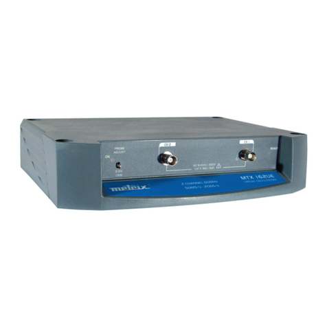
Metrix MTX 162UE TX 162UE User manual

Metrix
Metrix OX 530 User manual

Metrix
Metrix OX 5042 User manual

Metrix
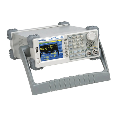
Metrix GX 1025 User manual

Metrix
Metrix TCX01 User manual

Metrix
Metrix CX 1651 User manual

Metrix
Metrix MX 604 User manual

Metrix
Metrix MX 59HD User manual