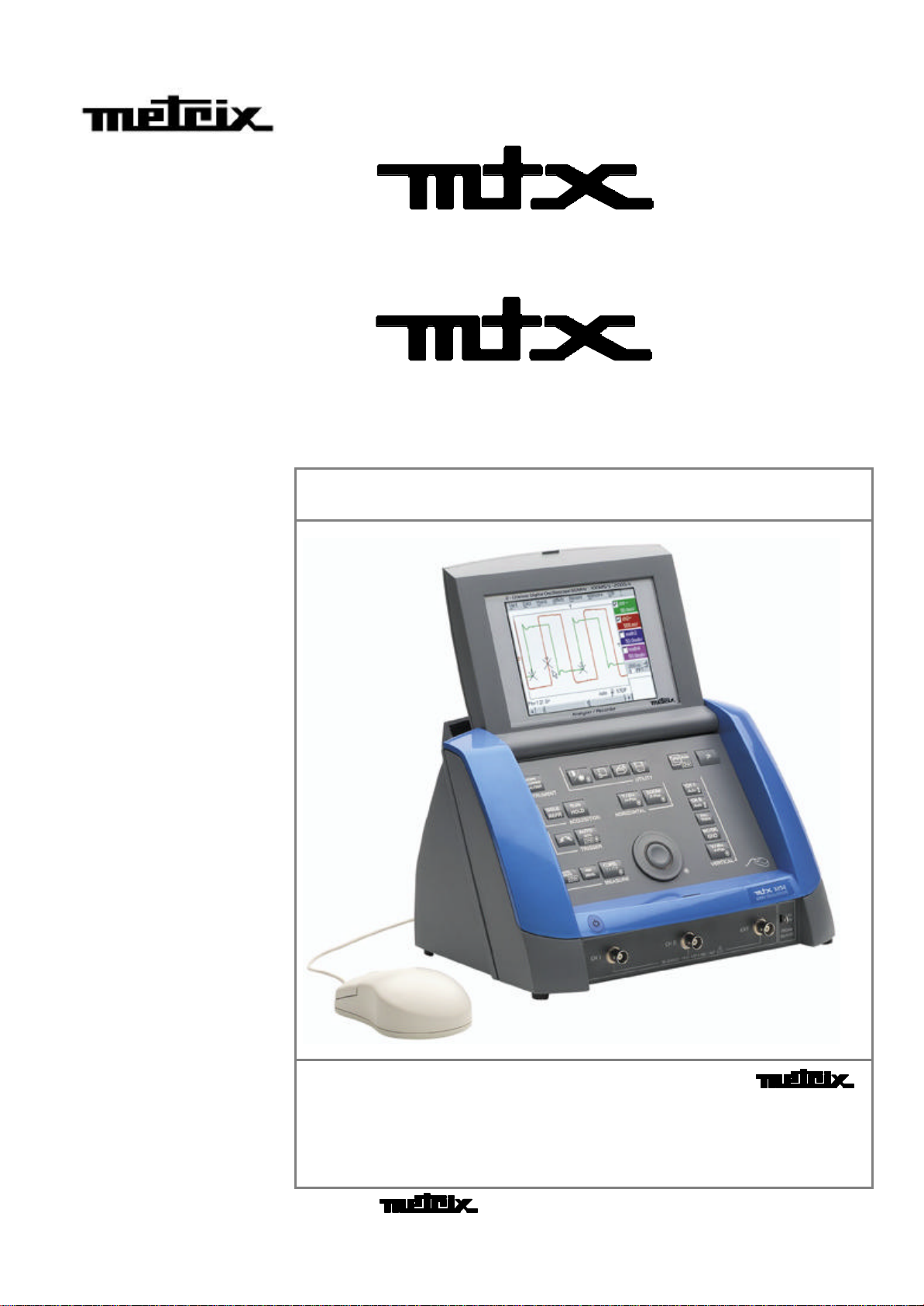
Metrix MTX 3352 User manual
32523252
mtxmtx 32523252 Monochrome - mtxmtx 3252-C3252-C Colour
6
6
6
0
0
0
M
M
M
H
H
H
z
z
z
T
T
T
w
w
w
o
o
o
-
-
-
c
c
c
h
h
h
a
a
a
n
n
n
n
n
n
e
e
e
l
l
l
d
d
d
i
i
i
g
g
g
i
i
i
t
t
t
a
a
a
l
l
l
o
o
o
s
s
s
c
c
c
i
i
i
l
l
l
l
l
l
o
o
o
s
s
s
c
c
c
o
o
o
p
p
p
e
e
e
s
s
s
33523352
mtxmtx 33523352 Monochrome - mtxmtx 3352-C3352-C Colour
1
1
1
0
0
0
0
0
0
M
M
M
H
H
H
z
z
z
T
T
T
w
w
w
o
o
o
-
-
-
c
c
c
h
h
h
a
a
a
n
n
n
n
n
n
e
e
e
l
l
l
d
d
d
i
i
i
g
g
g
i
i
i
t
t
t
a
a
a
l
l
l
o
o
o
s
s
s
c
c
c
i
i
i
l
l
l
l
l
l
o
o
o
s
s
s
c
c
c
o
o
o
p
p
p
e
e
e
s
s
s
O
O
Op
p
pe
e
er
r
ra
a
at
t
ti
i
in
n
ng
g
g
I
I
In
n
ns
s
st
t
tr
r
ru
u
uc
c
ct
t
ti
i
io
o
on
n
ns
s
s
Pôle Test et Mesure de CHAUVIN-ARNOUX
Parc des Glaisins - B. P. 330
6, avenue du Pré de Challes
F - 74943 ANNECY-LE-VIEUX Cedex
Tel. +33 (0)4.50.64.22.22 - Fax +33 (0)4.50.64.22.00
Copyright © X02414A00 - Ed. 1 - 01/03

Contents
I - 2Two-channel digital oscilloscope
Contents
General instructions Chapter I
Introduction.....................................................................page 4
Precautions and safety measures..........................................4
Symbols used.........................................................................5
Guarantee................................................................................5
Maintenance and metrological checking................................5
Unpacking - Repacking...........................................................5
Maintenance............................................................................5
Description of instrument Chapter II
Presentation...................................................................page 6
General view ...........................................................................6
Front panel (illustration)..........................................................7
Measurement terminal block (illustration)...............................7
Rear view (illustration).............................................................8
Front panel (description).........................................................9
Keys ......................................................................................10
Oscilloscope Mode Chapter III
Display..........................................................................page 14
Menus "Vert" Vertical menu........................20
"TRIG" Trigger menu........................24
"Horiz" Horizontal menu........................26
"Display" Display menu........................31
"Measure" Measurement menu........................33
"Memory" menu........................38
"Util" Utilities menu........................41
"?" Help menu........................45
“Harmonics” Mode Chapter IV
Display..........................................................................page 46
Menus "Vert" Vertical menu........................49
"Horiz" Horizontal menu........................52
"Display" Display menu........................53
"Memory" menu........................53
"Util" Utilities menu........................54
"?" Help menu........................54
Functional Description Chapter V
Preparation for use.......................................................page 55
Applications...........................................................................56

Contents
Two-channel digital oscilloscope I -
3
Contents
Technical Specifications Chapter VI
Vertical deflection.........................................................page 63
Horizontal deflection (time base)..........................................64
Trigger circuit........................................................................65
Acquisition chain...................................................................65
Display...................................................................................66
Miscellaneous .......................................................................66
Communication interfaces....................................................67
Remote programming...........................................................67
General characteristics Chapter VII
Environment.................................................................page 68
Mains power supply..............................................................68
EMC.......................................................................................68
Mechanical characteristics Chapter VII
Casing .........................................................................page 68
Packing..................................................................................68
Supply Chapter VII
Accessories..................................................................page 69
GThe content of this manual may not be reproduced in any form without the agreement of
the manufacturer.
General instructions
I - 4Two-channel digital oscilloscope
General instructions
Introduction You have just acquired a two-channel digital oscilloscope. It also features a
«harmonic analyser» mode and a « recorder» mode (pending).
Congratulations for your choice and thank you for your trust in the quality of
our products.
This instrument conforms to safety standard NF EN 61010-1 (2001), single
insulation, relative to electronic measurement instruments.
To obtain optimum service, read these instructions with care and comply with
the precautions for use.
Failure to comply with these warnings and/or user instructions is liable to
cause damage to the equipment and/or its components. This could be
dangerous to the user.
Precautions and
safety measures •This instrument has been designed for use:
- indoors,
- in a pollution degree 2 environment,
- at an altitude of less than 2000 m,
- at a temperature included between 0°C and 40°C
- with relative humidity of less than 80% to 40°C.
•
It can be used for measurements on circuits at 150V CAT II (300V CAT I, 300V
CAT II), relative to ground and can be supplied by a 240V CAT II network.
definition of
installation
categories
(cf. IEC 664-1)
CAT I: CAT I circuits are protected by devices designed to minimize transient
overvoltages at a low level.
E.g.: protected electronic circuits
CAT II : CAT II circuits are domestic or similar equipment power supply circuits
that can include average value transient overvoltages.
E.g.: power supply to domestic appliances and portable tools.
CAT III : CAT III circuits are circuits for power equipment power supplies which
may include high transient overvoltages.
E.g.: machine or industrial apparatus power supply.
CAT IV : CAT IV circuits are circuits that can include very high transient
overvoltages.
E.g.: energy inputs
before use •Comply with environment storage conditions.
•Make sure that the three-wire phase/neutral/ground power supply cord
supplied with the unit is in suitable condition. It conforms to standard NF
EN 61010-1 (2001) and must be connected to the instrument on the one
hand, and to the network on the other (variation from 100 to 240 VAC).
during
use •Read carefully all the notes preceded by the symbol .
•Connect the instrument to an outlet with a ground pin.
•The instrument power supply has automatically reset electric protection
operating after the fault has been eliminated.
•Be sure not to obstruct the aeration points.
•As a safety measure, use only suitable cords and accessories supplied with
the instrument or type approved by the manufacturer.
•When the instrument is connected to the measurement circuits, never
touch an unused terminal.
General instructions
Dual trace digital oscilloscope I - 5
Symbols
used Caution: Danger risk. Refer to the operating instructions.
Earth
Guarantee This equipment is guaranteed for 3 years against any material defect or
manufacturing faults, in conformity with the general conditions of sale.
During this period, the equipment may only be repaired by the
manufacturer. He reserves the right to carry out repair or replacement of all
or part of the equipment.
If the equipment is returned to the manufacturer, forward transport is at the
expense of the customer.
The guarantee does not apply in the event of:
•unsuitable use of the equipment or by association with incompatible
equipment
•modification of the equipment without the explicit authorization of the
manufacturer technical services
•operation by a person not approved by the manufacturer
•adaptation to a specific application not provided for in the equipment
definition or in the operating instructions
•impact, fall or flooding.
Maintenance and
metrological
checking
Before the equipment is opened,it must be disconnected from the
network supply and the measurement circuits, and the operator must not
become charged with any static electricity. This could cause the
destruction of internal parts.
Any adjustment, maintenance or repair of the energized equipment shall
only be undertaken by qualified personnel, after referring to the instructions
given in this document.
A qualified person is a person who is familiar with the installation,
construction, use and the hazards that exist. This person is authorized to
start up and shut down the installation and equipment in conformity with the
safety rules.
Return your instrument to your distributor for any work to be done within or
outside the guarantee.
Unpacking and
repacking All the equipment has been checked mechanically and electrically before
shipping.
On reception, carry out a quick check to detect any damage caused by
transport. If necessary, contact our commercial department immediately
and make all legal reservations with the carrier.
In the event of reshipping, it is preferable to use the original package.
Indicate as clearly as possible, by a note attached to the equipment, the
reasons for the return.
Servicing •Turn the instrument off.
•Clean it with a damp cloth and soap.
•Never use abrasive products or solvents.
•Allow to dry before any further use.
Description of instrument
II - 6Two-channel digital oscilloscope
Description of instrument
Presentation
This instrument is part of the new MTX range and has the particularity of
grouping together three units in one:
•a digital oscilloscope incorporating the FFT function, intended to
analyze the signals appearing in the electronics and electrotechnical
fields
•a harmonic analyser mode for breaking down two signals
simultaneously while representing their fundamental and their first 31
harmonics
•a recorder mode (pending) intended for the capture of single or slow
signals.
The instrument works at a constant acquisition depth of 50,000 points.
Memory management is organized from a system of files.
A large-size colour (or monochrome) LCD screen displays the applied signals,
together with all the adjustment parameters.
The main control functions are accessible directly from the front panel.
The adjustment parameters can be modified using the thumbwheel.
A graphic interface is similar to that of the PC and is used for:
•using the mouse to select the functions proposed by the pull-down
menus
•acting directly on objects (traces, cursors, etc.) displayed on the screen.
The adjustment parameters can thus be modified by a variety of means.
This instrument is completed by RS232/CENTRONICS interfaces as standard.
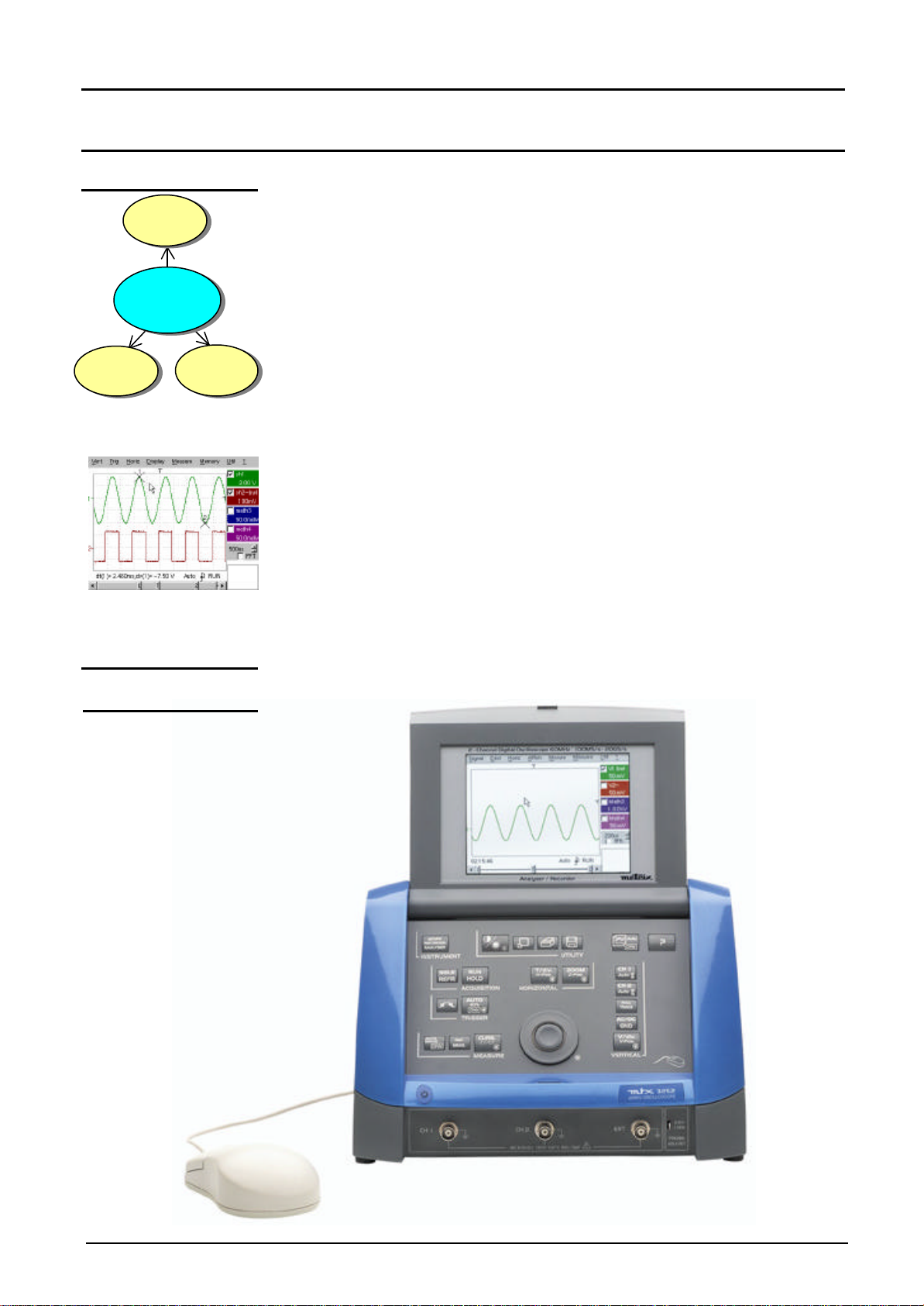
Overall view
mtx 3252
mtx 3352
Oscilloscope
Harmonic
analyser
Recorder

Description of instrument
Two-channel digital oscilloscope II - 7
Description of instrument (cont’d)
Front panel
(illustration)
Measurement
terminal block
CH1 signal input EXTernal trigger input
CH2 signal input Calibration output

Description of instrument
II - 8Two-channel digital oscilloscope
Description of instrument (cont’d)
Rear panel
SUBD 25-pin
female connector for
RS232/CENTRONICS
interfaces
SUBD 9-pin
male connector for
serial mouse
Mains
connector

Description of instrument
Two-channel digital oscilloscope II - 9
Description of instrument (cont’d)
Front panel
(description) The main features of the equipment can be obtained from the front panel.
They can also be modified directly by the mouse or using the menu toolbar.
1 startup / standby
button activates:
•startup (green LED) when pressed briefly.
•Setting the oscilloscope to standby (red LED) by a long press (> 3 s).
The files and the configuration are saved.
1 mouse / 2 keys connected to the back of the oscilloscope (SUBD9 connector for serial
mouse), used for: selection of menus,
function validation,
movement of symbols appearing on LCD screen.
•The menus appearing at the top of the screen and the submenus
selected by the mouse pointer open and are validated by the left key.
•The menus in the trace display zone
in the control zone
in the status zone
are opened with the right mouse key.
•The mouse can be used for moving:
symbols appearing in the main display zone:
trigger position, cursor position, display trace reference
symbols appearing in the bargraph:
trigger position, zoomed area cursor position
Position the mouse pointer on the symbol to be moved, holding the left
key of the mouse down during the movement to the desired position.
•Zooming in the display zone is possible using the mouse:
hold the left key down when defining the zone with the pointer.
1 rotary control
button •The outer wheel of this encoder is used for incrementing or
decrementing the selected setting (by rotation).
•The LED comes on when adjustment is possible using the wheel. After
20 seconds without action on the wheel, the LED goes out and the
function is no longer active.
•While the LED is on, pressing the central part of the encoder
(TOGGLE key) will toggle the adjustment of the main function to the
secondary function of the key. The Symbol : appears on the
keys concerned (except for the key opposite).
21 fleeting action
keys giving direct access to the more basic functions.
Description of instrument - Keys
II - 10 Two-channel digital oscilloscope
Description of instrument (cont’d)
Keys
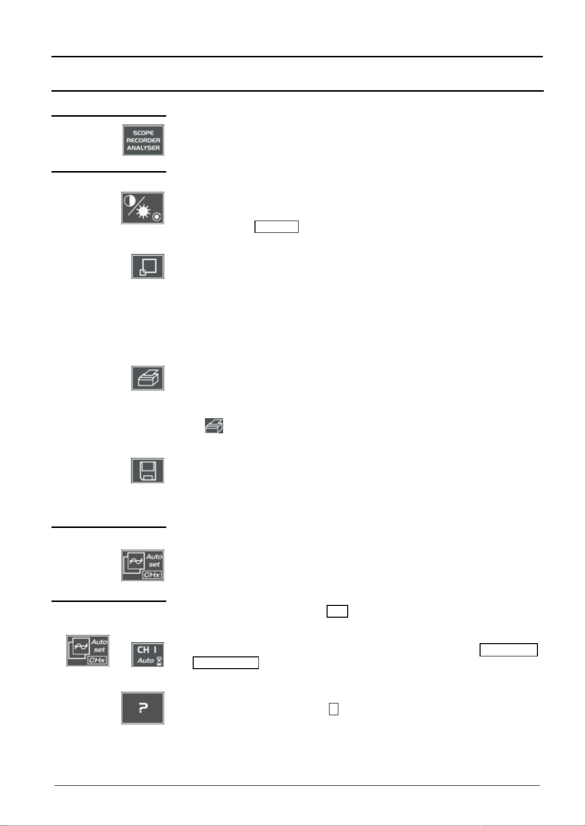
Pressing this key will configure the instrument in the following modes:
« oscilloscope»,
« harmonic analyser » or
« recorder» (pending).
4 «UTILITY» keys used for access to the LCD contrast adjustment using the thumbwheel.
The LED combined with the thumbwheel comes on àadjustment is accessible.
The thumbwheel TOGGLE key is used for switching the key assignment from
contrast adjustment to LCD brightness.
Pressing causes switchover from normal display mode to "full screen" display
mode (and vice versa).
The screen is organized in such a way as to leave an optimum trace plotting
surface area:
deletion of menu bar,
parameters of traces in time base,
bargraph.
Only permanent adjustments and measurements will remain.
launches a hardcopy depending on the configuration produced in the « Util »
and « Hardcopy » menus.
A second press before the process end will interrupt current printing.
If printing is impossible, a « Printing error » message will be sent.
The « » symbol is displayed in front of the measurement display zone
when printing is underway.
G
The first press will freeze the traces on the screen. They will be displayed in
plain language as a reference to be compared with further acquisition.
A second press will erase them: the latter will then be lost.
•Traces will be saved only in the « Memory àTrace àSave » menu.
•The reference memory will be accompanied by a reference Nr.
1 «AUTOSET» key used on channels to which a signal is applied to obtain optimum automatic
adjustment (General Autoset) of coupling, vertical sensitivity, time base, slope,
framing and trigger.
The lowest frequency signal is used as a triggering source.
If no trace is detected at the inputs, the autoset will be aborted.
Selective
«AUTOSET»
with
Simultaneously pressing with the CHx key (ch1 or ch2) will assign the
corresponding channel as trigger source, initiating an autoset which will take
this selection into consideration.
The CHx channel becomes active for adjustments by means of the AC/DC/GND
and V/div. V-Pos. keys.
1 help key activating or deactivating help on the keys.
Whenever a keyboard key is pressed, on-line help will be displayed for the
depressed key (except for the key
??
).
The functions associated with the keys will not be started up.
On-line help can also be deactivated with the mouse (icon at top right).
The keyboard then resumes normal operation.

Description of instrument – Keys
Two-channel digital oscilloscope II - 11
Description of instrument (cont’d)
2 «ACQUISITION»
keys
G
G
by successive pressing, select one of the following acquisition modes:
Single mode àSingle
Trigger mode àTrig’d
Automatic mode àAuto
«SINGLE » mode:
A single acquisition is triggered by pressing the RUN key. HOLD is authorized.
For any further acquisition, the triggering circuit must be reset by pressing the
RUN HOLD key.
«TRIGGER » mode:
The screen content is only refreshed in the presence of a triggering event
related to signals appearing at the oscilloscope (CH 1, CH 2, External or
Mains).
If there is no triggering event linked with the signals appearing at the inputs (or
if there is no signal at the inputs), the trace is not refreshed.
«AUTOMATIC » mode:
The screen content is refreshed even if the triggering level is not detected on
the signals appearing at the inputs.
In the presence of a triggering event, screen refreshing is managed as in the
«Triggered » mode.
•allows starting or stopping of acquisition in « TRIGGER » and
«AUTOMATIC » mode.
•resets the triggering circuit in the «Single» mode.
Acquisition is initiated according to the conditions defined by the
acquisition mode (SGLE REFR key).
Acquisition status is indicated in the status zone:
RUN = started READY = wait STOP = stopped
PRETRIG = before trigger POSTRIG = after trigger
2 «TRIGGER» keys
selects the trigger slope (positive or negative ) by successive
pressing.
The slope is indicated in the status zone.
G
sets the trigger level to the average value of the signal (50%) without
modifying the trigger coupling.
The thumbwheel is assigned to adjusting the trigger level.
Combined pressing with the CHx key launches the same function, but
previously sets the corresponding channel as triggering source.
No functions are associated with the TOGGLE key of the thumbwheel.
Description of instrument - Keys
II - 12 Two-channel digital oscilloscope
Description of instrument (cont’d)
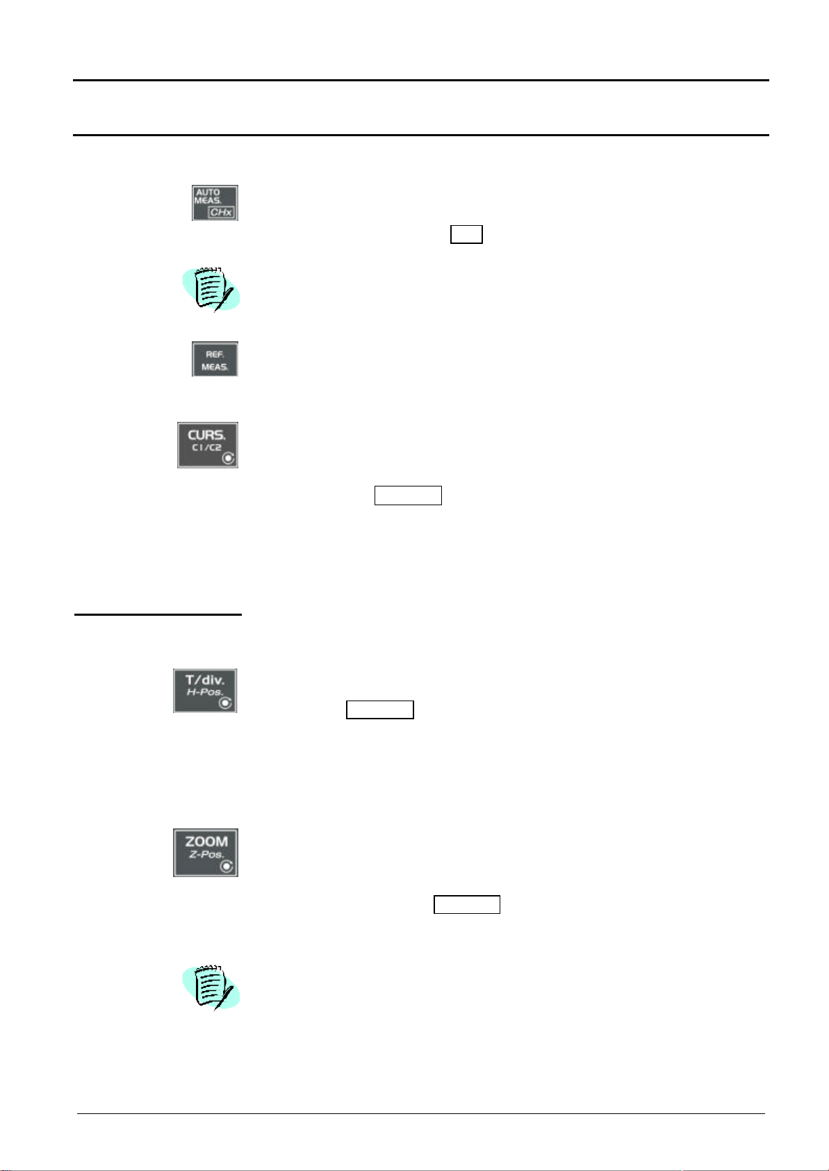
3 « MEASUREMENT »
keys activates or deactivates the display of the window for the 18 automatic
measurements of the reference trace.
Combined pressing with the CHx key displays the measurements on the
corresponding channel.
When the automatic measurement window is active, the left mouse button
is used for selecting at most 2 measurements that will appear in the status
zone at the bottom of the screen.
used for selecting (successive pressing) among the displayed traces, the
reference trace for the automatic and manual measurements.
Appears in the « Measurement » àReference menu.
activates or deactivates the cursor displays for manual measurements.
The LED combined with the thumbwheel comes on: the latter allows cursor
1 to be moved horizontally over the screen.
The thumbwheel TOGGLE key is used for moving from the cursor 1 to
cursor 2 horizontal movements and vice versa.
•The dt measurements made (time difference between the two cursors)
and the dv measurement (voltage deviation between the two cursors) are
reported in the status zone.
•The selected cursor position is entered into the active adjustment zone.
2 «HORIZONTAL»
keys used for access to adjustment of time base coefficient (T/div.) by
thumbwheel or for adjustment of horizontal position (H-Pos.) by the
thumbwheel TOGGLE key.
The LED associated with the wheel lights up àthe selected adjustment is
possible with this device.
The H-Pos. adjustment modifies the horizontal (time-related) position of the
trigger point.
G
activates or deactivates the « Zoom » function.
The LED associated with the wheel lights up: the thumbwheel is assigned
to the horizontal zoom coefficient adjustment.
Pressing the thumbwheel TOGGLE key makes it possible to change from
the horizontal zoom coefficient setting to Z-Pos. horizontal movement in the
zoomed zone.
A zone can be zoomed by tracing a rectangle around the zone to be
enlarged using the left mouse button. The sensitivity, time base and
horizontal and vertical alignment values are recalculated automatically.
If no zones to be zoomed are selected with the mouse, a simple horizontal
zoom by default will be performed with respect to the screen center.

Description of instrument – Keys
Two-channel digital oscilloscope II - 13
Description of instrument (cont’d)
Definition :
Validated channel = Display enable (trace displayed after RUN)
Displayed channel = Validated channel and trace on screen
Selected channel = Parameter settings enabled for this channel via the
keys:
and .
5 «VERTICAL» keys
Pressing one of these 2 keys for a long time generates a vertical autoset:
•This modifies the sensitivity and vertical positioning of the wheel in
question.
•It optimizes the display on the screen by activating and selecting the
channel.
The channel is displayed and selected. The thumbwheel adjusts the
sensitivity.
activates or deactivates the horizontal division by two, in the display zone.
The activated « Full Trace » function is indicated by:
- the presence of a continuous horizontal line in the middle of the display
zone
- the horizontal division in two of the graticule.
After the activation of the function:
- traces 1 and 3 are assigned to the upper part of the display,
- traces 2 and 4 are assigned to the lower part in order to eliminate their
superimposition.
The traces can then be moved vertically in the two zones.
used for selecting, by successive pressing, input coupling « AC », « DC »
or « GND » for the last channel selected.
Coupling is indicated in the channel parameters zone:
AC : , DC : nothing, ground: GND
Each press will provide access, through the thumbwheel, to the setting of
the sensitivity (V/div.) of the last channel selected.
Pressing the TOGGLE key will move from sensitivity adjustment to vertical
position adjustment (V-Pos.).
The LED associated with the wheel lights up àadjustment is possible with
this device.
Before pressing one of the
following keys: After pressing one of the
opposite keys:
The channel concerned is not
displayed. The channel is displayed and is
selected. The thumbwheel is
assigned to sensitivity adjustment.
The channel concerned is
displayed, but not selected. The channel is selected.
The channel concerned is
displayed and selected.
Press
on
or
The channel is deselected.

Oscilloscope Mode - Display
III - 14 Two-channel digital oscilloscope
Oscilloscope Mode
Display
Display
Composition The oscilloscope display is divided into 4 functional zones.
Direct access to
current adjustment
4. Menu bar
3. Display zone
1. Status zone
2. Control
zone
Display and
adjustment of
current value
Contrast
73.0%
Oscilloscope Mode - Display
Two-channel digital oscilloscope III - 15
Oscilloscope Mode (cont’d)
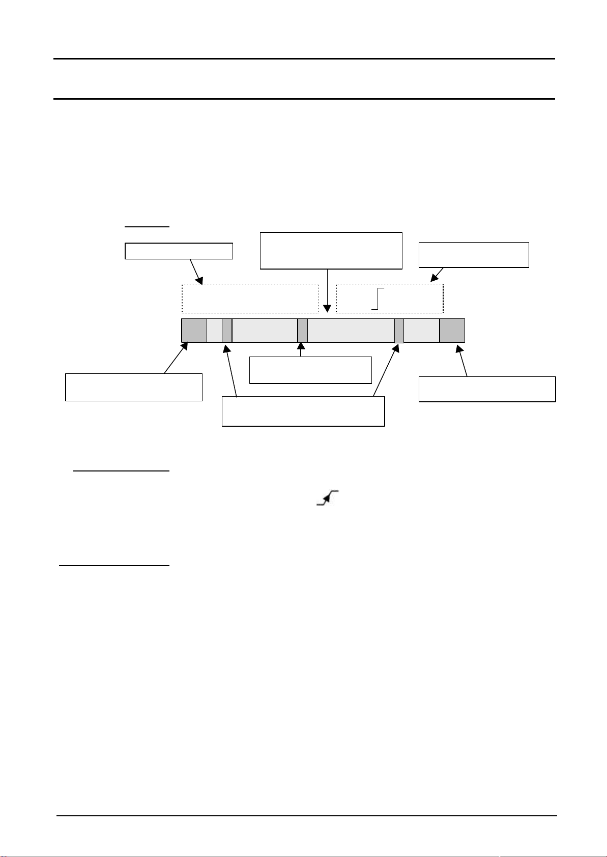
1. Status zone
Bargraph
G
Permanent settings
G
Cursormeasurements
Three types of general information appear in this zone:
•The bargraph represents the screen position, that of the trigger and
the cursors in the acquisition memory.
•Permanent instrument settings.
•Measurements when the cursors are on the screen (or display of time
otherwise).
Each bargraph element can be moved via the mouse left button.
This zone refers to the triggering status (mode, front, source, current
status).
@Example : AUTO . 1 STOP
When the cursor of the mouse is placed over this information, the right
mouse button will open the "Trigger parameters" menu.
This zone refers either to:
•horizontal (dt) and vertical (dv) difference between 2 cursors in the
case of manual measurements,
•phase measurement in the case of manual phase measurement (Ph).
(@Example : dv(1) = 500 µs, dv(1) = 2.00 V)
•automatic measurements selected by the "Automatic measurements"
or "Phase measurement" menu.
•time display, if no measurement has been selected.
33
4
Êdt(1)=110us dv(1)=100uV Trig 1 Pretrig
5
Position and movement
of time trigger
Position and movement of
manual cursors
Movement to left of screen in
acquisition memory
Movement of screen to right
in acquisition memory
Permanent
adjustments
Cursor Measurements
Representation and
movement of screen in
acquisition memory
T12

Oscilloscope Mode - Display
III - 16 Two-channel digital oscilloscope
Oscilloscope Mode (cont’d)
2. Control zone The parameters displayed in this zone are:
•The parameters of each channel and trace: display,
sensitivity, coupling,
bandwidth limit, vertical scale,
function, zoom.
•The time base value and the loading of the signal representation domain
(FFT)
•The active adjustment of the last selected element:
-trigger level
-trigger time position
-channel offset value
-X & Y position of cursor
-…
G•The mouse left key validates the channels and the functions.
•The « PP » symbol indicates whether a channel or function has been
selected, or whether the FFT mode has been selected.
•The adjustments of the time base (or frequency) and the value of the
active parameter can be made with the UP/DOWN button alongside
the current value display using the mouse key button.
•After a change to the time base, the corresponding sampling frequency
is entered into the adjustment zone.
•When the mouse is placed over the parameters of a channel or time
base value, the right mouse button opens the associated menus
directly.
-Sensitivity/Coupling and Vertical scale, for channels
-Vertical scale for the functions
-Source, trigger mode and RUN/STOP, for the time base
Indication and adjustment of last selected
adjustment
Display of trace parameters (in trace
color):
validity, coupling, bandwidth limit,
sensitivity
Display of ZOOM mode
Display of function parameters (in trace
color):
validity, value of division
Display of ZOOM mode
Value of time base coefficient (s/div) in
oscilloscope mode or frequency (Hz/div)
in FFT mode
Change of signal representation domain
(FFT selection)
25.0 %
Contrast

Oscilloscope Mode - Display
Two-channel digital oscilloscope III - 17
Oscilloscope Mode (cont’d)
The «Source» and « Trigger mode » menus are grouped together and
can be opened using the right mouse button by placing the pointer over
the time base zone.
RUN/STOP is used for starting and stopping acquisition from this menu.
The acquisition status is indicated in the screen status.
G•The symbol « PP » indicates the source and selected trigger mode
•The trigger source selectable from this menu is limited to the channels
(ch1 or ch2).
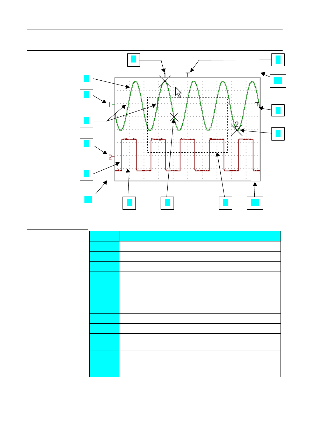
3. Display zone The displayed graphic elements associated with the traces in this zone
are:
•a trigger time position indicator
•a trigger level indicator
•a vertical position indicator for the reference level of each trace
•cursor position indicators linked with the curve for automatic
measurements
•cursor position indicators linked or not linked with the curve for manual
measurements
•the selection of a zoom zone
Oscilloscope Mode - Display
III - 18 Two-channel digital oscilloscope
Oscilloscope Mode (cont’d)
Display elements
Definition of
display
Trace affichée
7
9
∨∨
8
11
10
1
3
.
4
5
2
Items Elements
1Trace displayed
2Indication of displayed trace reference level vertical position
3Indication of time-related position of trigger
4Graticule division
5Automatic measurement cursor position indicator
6Manual measurement cursor position indicator
7Phase measurement cursor position indicator
8Trigger level position indicator
9Zoom zone selection
10 Time position output indicator of trigger outside displayed
window
11 Trigger level position output indicator outside displayed
window.
12 Channel level output indicator outside displayed window
1
>
v
ϕϕ
2
6
6
v
12
Oscilloscope Mode - Display
Two-channel digital oscilloscope III - 19
Oscilloscope Mode (cont’d)
Menu accessible
from display zone
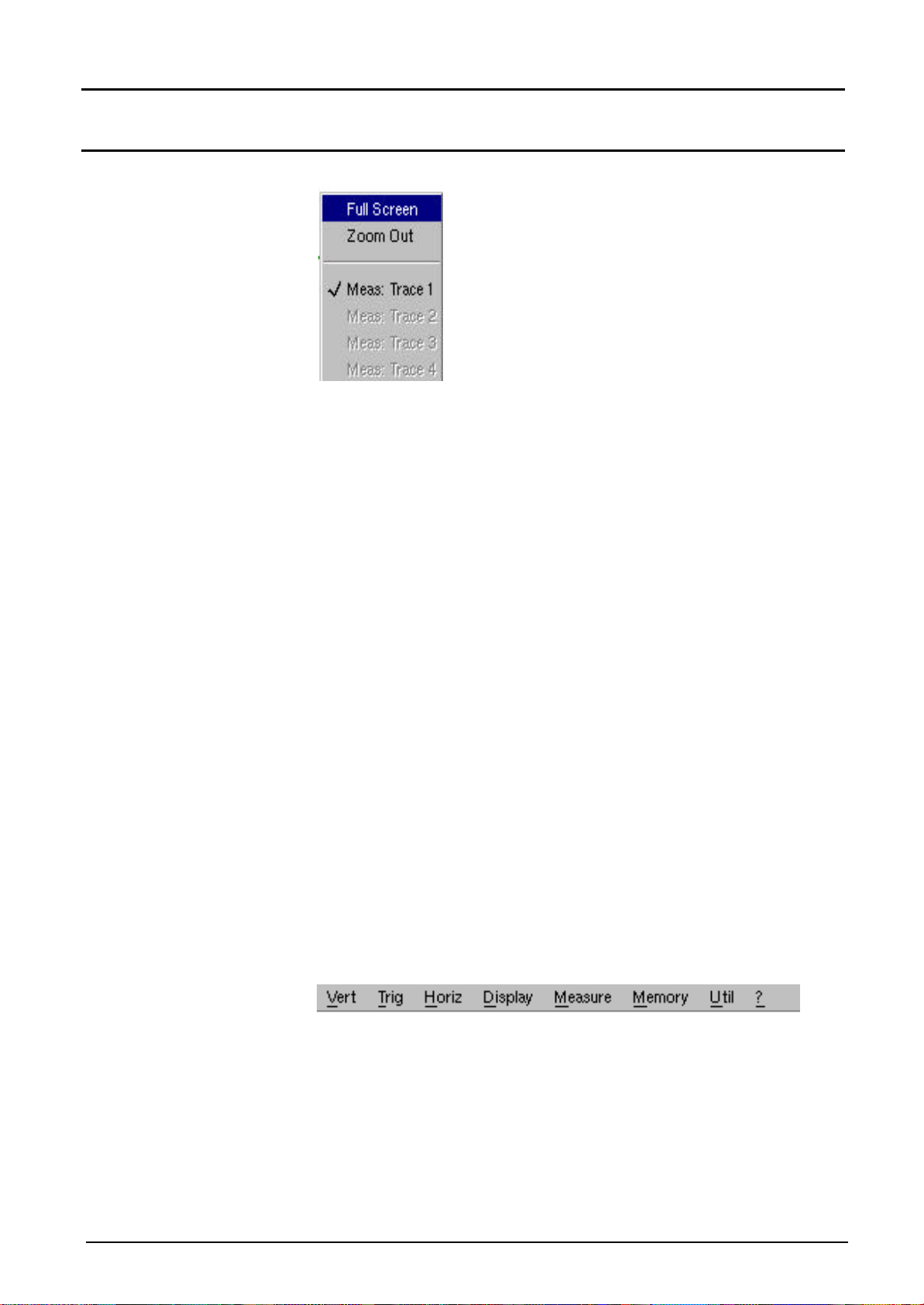
G
When the mouse pointer is placed in the
display zone, the right key gives direct
access to a display menu.
The « Full Screen » and « Zoom out »
options are directly accessible (see the
Display menu). The same applies to the
selection of the automatic and manual
measurement reference signal (see
Measurement menu).
The «üü » symbol indicates that the
display is in the «Full Screen » mode (if
present) and gives the reference trace for
automatic and manual measurements.
Zooming in the display zone is possible using a mouse, holding the left
mouse key down when the zone is selected by the pointer.
After zooming in to part of the screen, the sensitivities of the traces and
the time base are recalculated.
•The «z » symbol appears in the parameter display of the signals and
the time base.
•The zoomed section is represented in the bargraph.
•The « Zoom Out » menu (see Display menu) returns to the original
display.
•The horizontal zoom value is adjusted to assign a calibrated value to
the horizontal scale (zoom factor: x200 max.)
•If the zoom vertical selection is greater than 6 divisions, no vertical
zoom will be performed.
All the symbols appearing in the display zone:
-trigger indicators,
-trace position indicator,
-manual cursor position indicator,
-etc …
can be moved using the left button of the mouse.
The new modified symbol value is entered into the current adjustment
display zone.
4. Menu bar
All the oscilloscope functions can be accessed by the main menus.
Oscilloscope Mode - The « Vertical » menu
III - 20 Two-channel digital oscilloscope
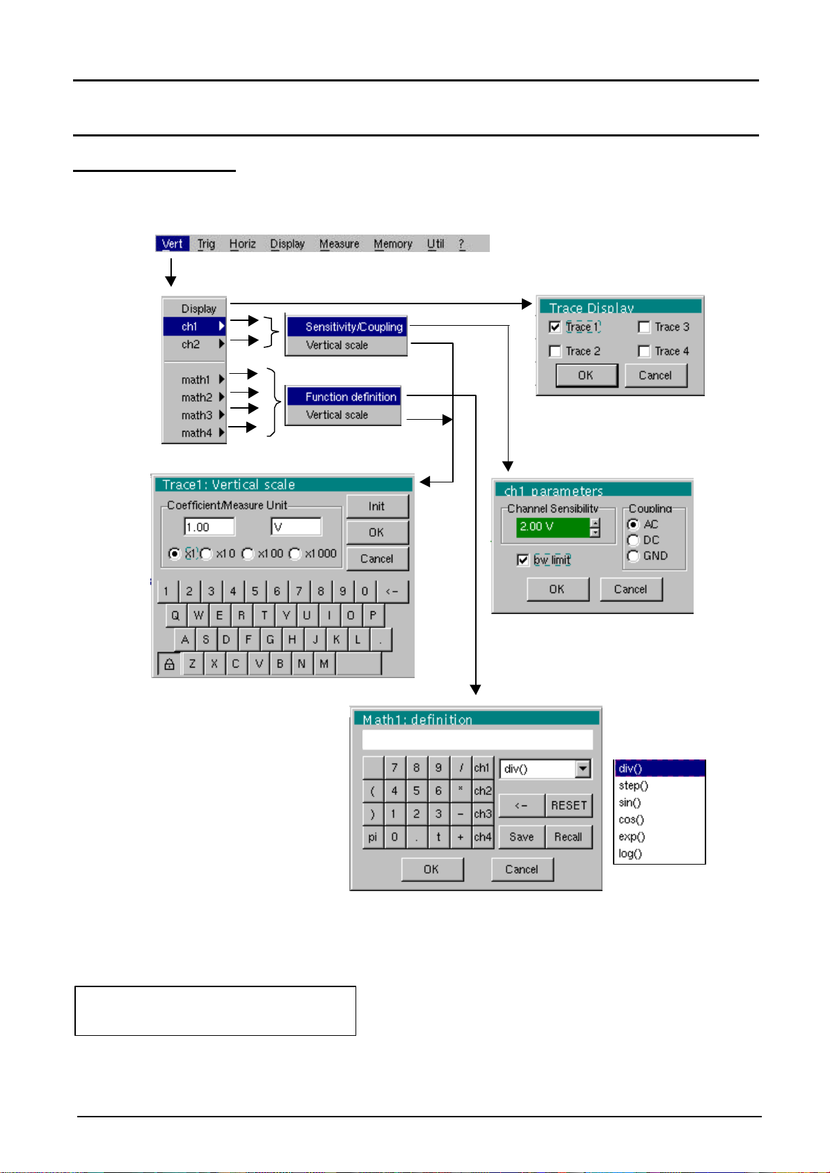
Oscilloscope Mode (cont’d)
The « Vert » Menu
(∗)
(∗)
(∗)
(∗)
(∗)
Only available in advanced mode
See §. Description, page 44.
ch1-ch2
This manual suits for next models
3
Table of contents
Other Metrix Test Equipment manuals

Metrix
Metrix GX-1030 User manual

Metrix
Metrix ScopiX IV Series User manual

Metrix
Metrix MX 407 User manual

Metrix
Metrix OX 5042 User manual

Metrix
Metrix CX 1651 User manual

Metrix
Metrix OX 832 User manual

Metrix
Metrix TCX01 User manual

Metrix
Metrix GX 1025 User manual

Metrix
Metrix MX 535 User manual

Metrix
Metrix MX 435D User manual

Metrix
Metrix MX 604 User manual

Metrix
Metrix MTX 3252e-C User manual

Metrix
Metrix MX 67 User manual

Metrix
Metrix MX2040 User manual

Metrix
Metrix CX 1651 User manual

Metrix
Metrix OX 6062-II User manual

Metrix
Metrix MX 407 User manual

Metrix
Metrix OX 530 User manual

Metrix
Metrix HandScope OX5022B User manual

Metrix
Metrix HI 803 Specification sheet


