3
1
2
IMO-210EN
GENERAL
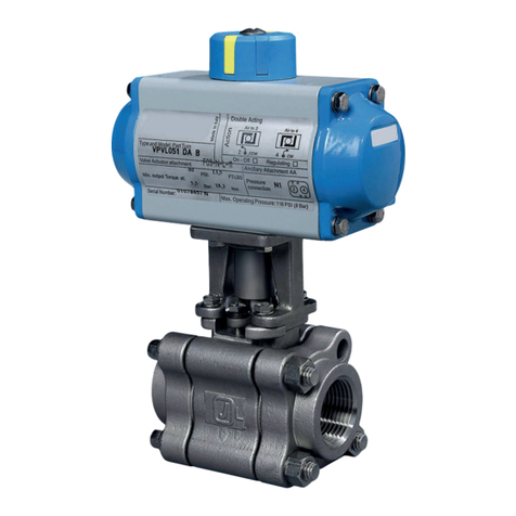
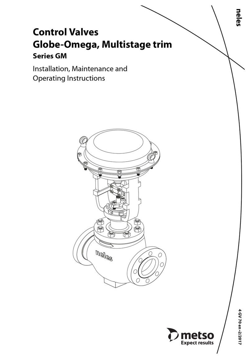
This instruction manual contains important information
regarding the installation, operation and troubleshooting
for the Jamesbury 1/2" – 2" (DN 15 – 50) Standard Bore,1/2"
– 1-1/2" (DN 15 – 40) Full Bore Series 4000 Model B 3-
Piece Ball Valves with ISO Bonnet. Please read the instruc-
tions carefully and save them for future reference.
1.1 WARNING
FOR YOUR SAFETY, TAKE THE FOLLOWING PRECAUTIONS BEFORE
REMOVING THE VALVE FROM THE LINE, OR BEFORE ANY DISASSEM-
BLY.
1. DURING REMOVAL AND DISASSEMBLY, WEAR ANY PROTECTIVE
EQUIPMENT NORMALLY REQUIRED TO PROTECT AGAINST DIS-
CHARGE OF TRAPPED FLUID.
2. DEPRESSURIZE THE LINE AND VALVE AS FOLLOWS:
A. PLACE THE VALVE IN THE OPEN POSITION AND DRAIN THE
LINE.
B. CYCLE THE VALVE TO RELIEVE RESIDUAL PRESSURE IN THE
BODY CAVITY BEFORE REMOVAL FROM THE LINE.
C. AFTER REMOVAL,AND BEFORE ANY DISASSEMBLY, CYCLETHE
VALVE AGAIN SEVERAL TIMES.
3. SEAT AND BODY RATINGS - THE PRACTICAL AND SAFE USE OF
THIS PRODUCT IS DETERMINED BY BOTH THE SEAT AND BODY
RATING. READ THE NAME TAG AND CHECK BOTH RATINGS. THIS
PRODUCT IS AVAILABLE WITH A VARIETY OF SEAT MATERIALS.
SOME OF THE SEAT MATERIALS HAVE PRESSURE RATINGS THAT
ARE LESS THAN THE BODY RATINGS. ALL OF THE BODY AND
SEAT RATINGS ARE DEPENDENT ON VALVE TYPE AND SIZE,
SEAT MATERIAL AND TEMPERATURE. DO NOT EXCEED THESE
RATINGS.
NOTE: OPTIONAL ROUND AND OVAL HANDLES ARE AVAILABLE FOR
THESE VALVES IN PLACE OF LEVER HANDLES.
INSTALLATION
Screwed End Style - Use standard piping practices to
install valves with threaded end caps. When tightening
valve to pipe, apply wrench to end cap nearest the pipe
being worked.
Weld End Style - Only valves with UHMWPE or Delrin®
seats must be disassembled before welding in line. A
warning tag and replacement body seals are affixed to
valves with these seat materials. VALVES WITH OTHER SEAT
MATERIALS SHOULD BE WELDED IN-LINE FULLY ASSEMBLED.
1. Only a qualified person should weld, as outlined in
Section IX of the ASME Boiler Construction Code.
2. Cycle the valve to the fully open position.
3. Remove or protect the handle or actuator from weld
splatter or arc strikes.
4. Weld by applying a recommended 1/8" (3.2 mm) max.
weld bead per pass around each end cap. CAUTION:
DO NOT heat the center section over 350˚F (176.7˚C).
Use a temperature stick and a wet cloth wrapped
around the center section to prevent overheating.
5. For welds that require multiple passes to achieve weld
size,stop after each pass and carefully monitor the valve
body temperature.
6. After sufficient cooling of the valve, replace the handle
or actuator.
IMPORTANT: If the body seals (6) and (18) are removed for
welding, DO NOT REUSE THEM. When reassembling the
valve, put new seals back into the grooves. Body seal kits
are provided in (Table 5). Tighten the body bolts to the
torques listed in (Table 1).
TABLE 1
Body Bolt / Hex. Nut Torque
Valve Size
Full Port Size In ( ) Torque FT•LBS Torque N•m
1/2" (1/2")
DN 15 (DN 15) 10 13
3/4"
DN 20 14 19
1" & 1-1/4" (3/4" & 1")
DN 25 & 32 (DN 20 & 25) 26 35
1-1/2" & 2" (1-1/4" & 1-1/2")
DN 40 & 50 (DN 32 & 40) 63 85
CAUTION: IF THE VALVE IS BEING DISASSEMBLED FOR
WELDING, DO NOT CUT OR SCRATCH THE SEATS, SEALS
AND SEALING SURFACES. DAMAGE TO THE SEALING
SURFACES MAY CAUSE LEAKAGE.
After valve is in line,or before any testing,tighten compression
plate hex.head cap screws according to the MAINTENANCE
Section below.
3 MAINTENANCE
Routine maintenance consists of tightening the compression
plate hex. head cap screws periodically to compensate for
the wear caused by the stem turning against the stem seals.
Check to make sure that the compression plate hex. head
cap screws are tightened to the torque listed in (Table 2).
Overhaul maintenance consists of replacing seats and seals.
A standard service kit consisting of these parts may be
obtained from your Jamesbury Distributor (see Table 4).


