Communicate via
Quick Installation Guide
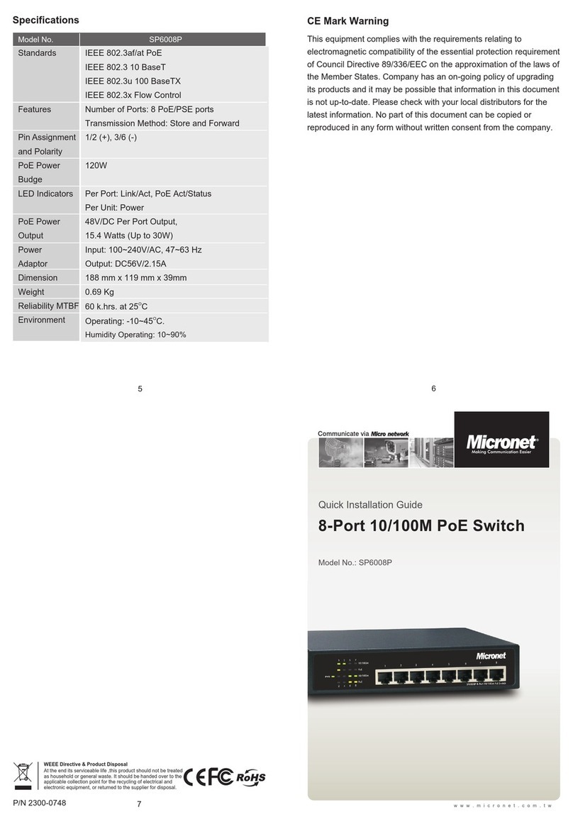
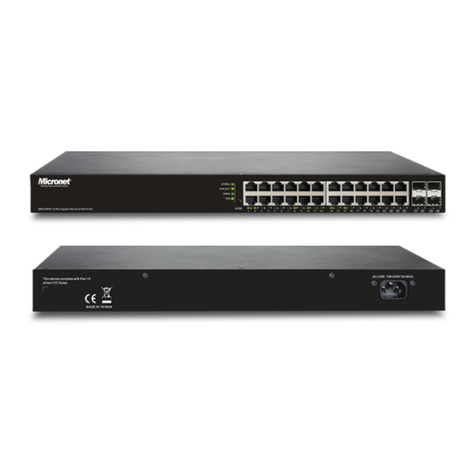
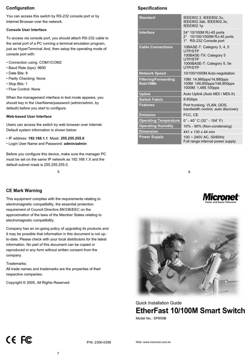
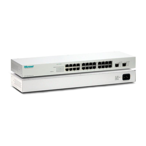
Model No.: SP6124A
P/N 2300-0678
6
5
7
WEEE Directive & Product Disposal
At the end its serviceable life ,this product should not be treated
as household or general waste. It should be handed over to the
applicable collection point for the recycling of electrical and
electronic equipment, or returned to the supplier for disposal.
Hardware Installation
This switch can be placed on your desktop directly, or mounted in a
rack. Users can display all the features of the switch by simply
attaching the cables and turning the power on.
Desktop Installation
1.Attach the provided robber feet to the bottom of the switch to keep
the switch from slipping. The recommend position has been
square-marked.
2.Install the switch on a level surface that can support the weight of
the unit and the relevant components.
3.Plug the switch with the female end of the provided power cord
and plug the male end to the power outlet.
Rack-mount Installation
The switch can be mounted in a standard 19” rack with two optional
rack mounting brackets and screws, which are used for rack
mounting the unit.
Procedures to rack-mount the switch in the rack:
1.Disconnect all the cables from the switch before continuing.
2.Place the unit the right way up on a hard, flat surface with the
front facing you.
3.Locate a mounting bracket over the mounting holes on one side
of the unit.
4.Insert the screws and fully tighten with a suitable screwdriver.
5.Repeat the two previous steps for the other side of the unit.
6.Insert the unit into the rack and secure with suitable screws.
7.Reconnect all the cables.
1.
1.
1.
1.
1.
1.
Network Cables
1. Crossover or straight-through cable: All the ports on the
switch support Auto-MDI/MDI-X functionality. Both straight-through
or crossover cables can be used to connect the switch with PCs as
well as other devices like switches, hubs or routers.
2. Category 3, 4, 5, 5e or 6 UTP/STP cable: To make a valid
connection and obtain the optimal performance, appropriate cables
corresponding to different transmitting/receiving speed is required.
To choose a suitable cable, please refer to the following table.
Specification
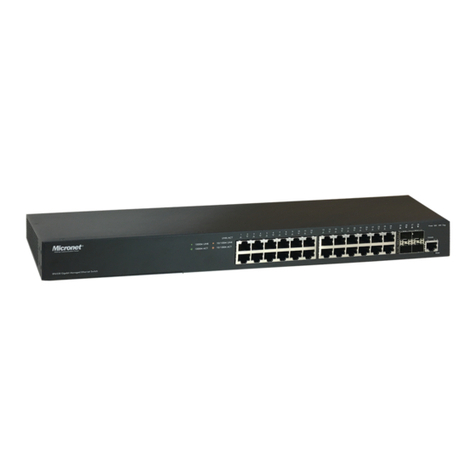
24-port Gigabit Switch
[Tips:] To performing this switch well, we strongly recommend
below installation environment:
1. The switch is placed with appropriate ventilation environment. A
minimum 25mm space around the unit is recommended.
2. The switch and the relevant components are away from sources
of electrical noise such as radios, transmitters and
broadband amplifiers.
3. The switch is away from environments beyond
recommend moisture.
1.
1.
1.
1.
IEEE802.3, 10Base-T
IEEE802.3u, 100Base-TX
IEEE802.3ab, 1000Base-T
IEEE802.3az (EEE)
IEEE802.3x Flow Control
24 10/100/1000 Mbps RJ-45 ports
10Mbps/100Mbps: Full-duplex,
Half-duplex 1000Mbps: Full-duplex
48 Gbps
8K
9K Bytes
3.5Mbits
100-240V, 50-60Hz
430 x 250 x 44 mm
OO
Operating: 0~40 C, Storage: -20~70 C
Operating: 10~90% (Non-Condensing)
Standards
Interface
NWay Protocol Support
Switching Capacity
MAC Address
Jumbo Frame
Packet Buffer
Power
Dimension
Temperature
Humidity
Network Speed Cable Type
10M
100M
Max. Length
Cat. 3,4,5 5e
UTP/STP
Cat. 5
UTP/STP
100 meters
100 meters
1000M Cat. 5e, 6
UTP/STP
100 meters
www.micronet.com.tw
