MiTAC TYAN S8030 User manual

http://www.tyan.com
1
S8030
(for PCB OOY)
Version 1.0i
Copyright
Copyright © 2020 MITAC COMPUTING TECHNOLOGY CORPORATION. All rights
reserved. No part of this manual may be reproduced or translated without prior
written consent from MITAC COMPUTING TECHNOLOGY CORPORATION.
Trademark
All registered and unregistered trademarks and company names contained in this
manual are property of their respective owners including, but not limited to the
following.
TYAN®is a trademark of MITAC COMPUTING TECHNOLOGY CORPORATION.
AMD®is a trademark of AMD®Corporation.
AMI, AMI BIOS are trademarks of AMI Technologies.
Microsoft®, Windows®are trademarks of Microsoft Corporation.
Nuvoton®is a trademark of Nuvoton Technology Corporation.
Notice
Information contained in this document is furnished by MITAC COMPUTING
TECHNOLOGY CORPORATION and has been reviewed for accuracy and reliability
prior to printing. MITAC assumes no liability whatsoever, and disclaims any express
or implied warranty, relating to sale and/or use of TYAN®products including liability
or warranties relating to fitness for a particular purpose or merchantability. MITAC
retains the right to make changes to product descriptions and/or specifications at
any time, without notice. In no event will MITAC be held liable for any direct or
indirect, incidental or consequential damage, loss of use, loss of data or other
malady resulting from errors or inaccuracies of information contained in this
document.

http://www.tyan.com
2

http://www.tyan.com
3
Contents
Before you begin….................................................................................... 4
Chapter 1: Instruction ................................................................................ 5
1.1 Congratulations ................................................................................. 5
1.2 Hardware Specifications.................................................................... 5
1.3 Software Specifications ................................................................... 10
Chapter 2: Board Installation................................................................... 11
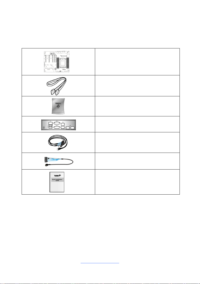
2.1 Board Image .................................................................................... 12
2.2 Block Diagram ................................................................................. 13
2.3 Mainboard Mechanical Drawing ...................................................... 14
2.4 Board Parts, Jumpers and Connectors ........................................... 15
2.5 LED Definitions................................................................................ 25
2.6 Installing the Processor and Heat sink ............................................ 26
2.7 Tips on Installing Motherboard in Chassis ...................................... 30
2.8 Installing the Memory ...................................................................... 32
2.9 Attaching Drive Cables .................................................................... 35
2.10 Installing Add-In Cards .................................................................. 36
2.11 Connecting External Devices ........................................................ 37
2.12 Installing the Power Supply ........................................................... 38
2.13 Finishing Up................................................................................... 39
Chapter 3: BIOS Setup ............................................................................. 41
3.1 About the BIOS................................................................................ 41
3.2 Main Menu....................................................................................... 43
3.3 Advanced Menu............................................................................... 44
3.4 Chipset Menu .................................................................................. 92
3.5 AMD CBS ........................................................................................ 95
3.6 Server Management ......................................................................118
3.7 Security..........................................................................................126
3.8 Boot ...............................................................................................131
3.9 Save & Exit ....................................................................................134
Chapter 4: Diagnostics........................................................................... 137
4.1 Flash Utility ....................................................................................137
4.2 AMIBIOS Post Code (Aptio) .......................................................... 138
Appendix I: Fan and Temp Sensors ..................................................... 145
Appendix II: M.2 Latch Installation........................................................ 149
Glossary................................................................................................... 153
Technical Support .................................................................................. 159

http://www.tyan.com
4
Before you begin…
Check the box contents!
The retail motherboard package should contain the following:
1 x S8030 Motherboard
2 x SATA Signal Cable
2 x M.2 Snap Clip Kit
1 x Rear I/O Shield
SlimSAS 8i to 2*U.2 (NVMe) cable x 2
(Optional) FRU# FRU-CS-1230
miniSAS HD to 4*SATA cable x3
(Optional) FRU# FRU-CS-1240
1 x S8030 Quick reference guide
IMPORTANT NOTE:
Sales sample may not come with the accessory listed above.
Please contact your sales representative to help order accessory for your
evaluation.

http://www.tyan.com
5
Chapter 1: Instruction
1.1 Congratulations
You have purchased the powerful TYAN® S8030 motherboard. The S8030 is
designed to support single AMD EPYC™ 7002/7003 Series Processor, and up to
512GB RDIMM / 1,024GB LRDIMM / 2,048GB LRDIMM 3DS DDR4 memory.
Leveraging advanced technology from AMDl®, the S8030 is capable of offering
scalable 32 and 64-bit computing, high-bandwidth memory design, and lightning-
fast PCI-E bus implementation.
The S8030 not only empowers you in today’s demanding IT environment but also
offers a smooth path for future application upgradeability. All of these rich feature
sets provides the S8030 with the power and flexibility to meet demanding
requirements for today’s IT environments.
Remember to visit the TYAN® website at http://www.tyan.com. There you can
find all the information on all TYAN®products as well as all the supporting
documentation, FAQs, Drivers and BIOS upgrades.
1.2 Hardware Specifications
S8030 (S8030GM2NE)
Processor
Q'ty / Socket Type (1) AMD Socket SP3
Supported CPU Series (1) AMD EPYC™ 7002/7003
Series Processor
Configurable Thermal
Design Power (cTDP)
Wattage
Max up to 280W
Memory
Supported DIMM
Qty (8) DIMM slots
DIMM Type / Speed DDR4 ECC RDIMM/RDIMM
3DS/LRDIMM/LRDIMM 3DS 3200
Capacity
Up to 512GB RDIMM/ 1,024GB
LRDIMM/ 2,048GB LRDIMM 3DS
*Follow latest AMD DDR4 Memory
POR
Memory channel 8 Channels per CPU
Memory voltage 1.2V
Expansion Slots PCI-E (5) PCI-E Gen4 x16 slots
LAN Q'ty / Port (2) GbE ports + (1) GbE dedicated
for IPMI

http://www.tyan.com
6
Controller Intel I210
PHY Realtek RTL8211E
Storage
SATA
Connector (2) SATA, (3) SFF-8643
for (12) SATA ports
Controller Direct from AMD EPYC
CPU
Speed 6Gb/s
RAID N/A
NVMe
Connector (M.2)
(2) 22110/2280
(by PCI-E Gen. 3
x4/SATA interface)
Connector (Slim
SAS)
(2) SFF-8654 for (4)
NVMe ports
Graphic
Connector type D-Sub 15-pin
Resolution Up to 1920x1200
Chipset Aspeed AST2500
Input /Output
USB (2) USB3.1 Gen1 ports (@ rear)
COM (1) header
VGA (1) D-Sub 15-pin VGA port (@ rear)
RJ-45 (2) GbE ports,
(1) GbE dedicated for IPMI
Front Panel (1) 2x12-pin SSI front panel header
SATA
(2) SATA-III connectors,
(12) SATA ports from (3) Mini SAS
HD connectors
Power ATX 24-pin + (2) 8-pin power
connectors
System Monitoring
Chipset Aspeed AST2500
Fan Total (4) 4-pin headers
Temperature Monitors temperature for CPU &
memory & system environment
Voltage Monitors voltage for CPU, memory,
chipset & power supply
LED
Fan fail LED indicator, Over
temperature warning indicator, Fan
& PSU fail LED indicator
Others Watchdog timer support
Server Management
AST2500 iKVM
Feature
24-bit high quality video
compression, Supports storage over
IP and remote platform-flash, USB

http://www.tyan.com
7
2.0 virtual hub
AST2500 IPMI
Feature
IPMI 2.0 compliant baseboard
management controller (BMC),
10/100/1000 Mb/s MAC interface
BIOS
Brand / ROM size AMI, 32MB
Feature
Hardware Monitor, Boot from USB
device/PXE via LAN/Storage, User
Configurable FAN PWM Duty Cycle,
Console Redirection, ACPI sleeping
states S0, S5, ACPI 6.2, SMBIOS
3.2/PnP/Wake on LAN
Physical Dimension
Form Factor ATX
Board Dimension 12" x 9.9" (305 x 250.8mm)
Operating System OS supported list Please refer to our AVL support
lists.
Regulation
FCC (SDoC) Class A
CE (DoC) Class A
Operating Environment
Operating Temp. 10° C ~ 35° C (50° F~ 95° F)
Non-operating Temp. - 40° C ~ 70° C (-40° F ~ 158° F)
In/Non-operating
Humidity 90%, non-condensing at 35° C
RoHS RoHS 6/6 Compliant Yes
Package Contains
Motherboard (1) S8030
Motherboard
Manual (1) Quick Installation
Guide
I/O Shield (1) I/O Shield
Cable SATA (2) SATA signal
cables
S8030 (S8030GM4NE-2T)
Processor
Q'ty / Socket Type (1) AMD Socket SP3
Supported CPU Series (1) AMD EPYC™ 7002/7003
Series Processor
Configurable Thermal
Design Power (cTDP)
Wattage
Max up to 280W
Memory Supported DIMM (8) DIMM slots

http://www.tyan.com
8
Qty
DIMM Type / Speed DDR4 ECC RDIMM/RDIMM
3DS/LRDIMM/LRDIMM 3DS 3200
Capacity
Up to 512GB RDIMM/ 1,024GB
LRDIMM/ 2,048GB LRDIMM 3DS
*Follow latest AMD DDR4 Memory
POR
Memory channel 8 Channels per CPU
Memory voltage 1.2V
Expansion Slots PCI-E (5) PCI-E Gen4 x16 slots
LAN
Q'ty / Port (2) 10GbE ports, (2) GbE ports,
(1) GbE dedicated for IPMI
Controller Intel I210-AT, Intel X550-BT2
PHY Realtek RTL8211E
Storage
SATA
Connector (2) SATA, (3) SFF-8643
for (12) SATA ports
Controller Direct from AMD EPYC
CPU
Speed 6Gb/s
RAID N/A
NVMe
Connector (M.2)
(2) 22110/2280
(by PCI-E Gen. 3
x4/SATA interface)
Connector (Slim
SAS)
(2) SFF-8654 for (4)
NVMe ports
Graphic
Connector type D-Sub 15-pin
Resolution Up to 1920x1200
Chipset Aspeed AST2500
Input /Output
USB (2) USB3.1 Gen1 ports (@ rear)
COM (1) header
VGA (1) D-Sub 15-pin VGA port (@ rear)
RJ-45 (2) 10GbE ports, (2) GbE ports,
(1) GbE dedicated for IPMI
Front Panel (1) 2x12-pin SSI front panel header,
(2) 1x2 header
SATA
(2) SATA-III connectors, (12) SATA
ports from (3) Mini SAS HD
connectors
Power ATX 24-pin + (2) 8-pin power
connectors

http://www.tyan.com
9
System Monitoring
Chipset Aspeed AST2500
Fan Total (4) 4-pin headers
Temperature Monitors temperature for CPU &
memory & system environment
Voltage Monitors voltage for CPU, memory,
chipset & power supply
LED
Fan fail LED indicator, Over
temperature warning indicator, Fan
& PSU fail LED indicator
Others Watchdog timer support
Server Management
AST2500 iKVM
Feature
24-bit high quality video
compression, Supports storage over
IP and remote platform-flash, USB
2.0 virtual hub
AST2500 IPMI
Feature
IPMI 2.0 compliant baseboard
management controller (BMC),
10/100/1000 Mb/s MAC interface
BIOS
Brand / ROM size AMI, 32MB
Feature
Hardware Monitor, Boot from USB
device/PXE via LAN/Storage, User
Configurable FAN PWM Duty Cycle,
Console Redirection, ACPI sleeping
states S0, S5, ACPI 6.2, SMBIOS
3.2/PnP/Wake on LAN
Physical Dimension
Form Factor ATX
Board Dimension 12" x 9.9" (305 x 250.8mm)
Operating System OS supported list Please refer to our AVL support
lists.
Regulation
FCC (SDoC) Class A
CE (DoC) Class A
Operating Environment
Operating Temp. 10° C ~ 35° C (50° F~ 95° F)
Non-operating Temp. - 40° C ~ 70° C (-40° F ~ 158° F)
In/Non-operating
Humidity 90%, non-condensing at 35° C
RoHS RoHS 6/6 Compliant Yes
Package Contains
Motherboard (1) S8030
Motherboard
Manual (1) Quick Installation
Guide
I/O Shield (1) I/O Shield

http://www.tyan.com
10
Cable SATA (2) SATA signal
cables
1.3 Software Specifications
For OS (operation system) support, please check with TYAN®support for latest
information.

http://www.tyan.com
11
Chapter 2: Board Installation
You are now ready to install your motherboard.
How to install our products right… the first time
The first thing you should do is reading this user’s manual. It contains important
information that will make configuration and setup much easier. Here are some
precautions you should take when installing your motherboard:
(1) Ground yourself properly before removing your motherboard from the
antistatic bag. Unplug the power from your computer power supply and
then touch a safely grounded object to release static charge (i.e. power
supply case). For the safest conditions, MITAC recommends wearing a
static safety wrist strap.
(2) Hold the motherboard by its edges and do not touch the bottom of the
board, or flex the board in any way.
(3) Avoid touching the motherboard components, IC chips, connectors,
memory modules, and leads.
(4) Place the motherboard on a grounded antistatic surface or on the antistatic
bag that the board was shipped in.
(5) Inspect the board for damage.
The following pages include details on how to install your motherboard into your
chassis, as well as installing the processor, memory, disk drives and cables.
Caution!
1. To avoid damaging the motherboard and associated
components, do not use torque force greater than
5~7 kgf/cm (4.35 ~ 6.09 lb/in) on each mounting
screw for motherboard installation.
2. Do not apply power to the board if it has been
damaged.

http://www.tyan.com
12
2.1 Board Image
S8030
This picture is representative of the latest board revision available at the time of
publishing. The board you receive may not look exactly like the above picture.

http://www.tyan.com
13
2.2 Block Diagram
S8030 Block Diagram

http://www.tyan.com
14
2.3 Mainboard Mechanical Drawing

http://www.tyan.com
15
2.4 Board Parts, Jumpers and Connectors
This diagram is representative of the latest board revision available at the time of
publishing. The board you receive may not look exactly like the above diagram. But
for the DIMM number please refer to the above placement for memory installation.
For the latest board revision, please visit our web site at http://www.tyan.com.

http://www.tyan.com
16
Jumpers & Connectors
Connectors
1 Micro SD Connector (J19) 16 System Fan Connector (J21)
2 System Fan Connector (J42) 17 SATA Connector (J22)
3 NVMe/SATA M.2 Slot (CN3) 18 SATA Connector (J14)
4 IPMB Header (J67) 19 System Fan Connector (J17)
5 Front USB3.1 Header (J32) 20 2x12pin PWR Connector (J60)
6 TPM Header (J40) 21 PSMI Connector (J61)
7 NVMe/SATA M.2 Slot (CN1) 22 CPU Fan Connector (J34)
8 Front Panel Header (J38) 23 2x4pin PWR Connector (J63)
9 Slim SAS 8x Connector (CN4) 24 ID Button
10 Mini SAS HD Connector (J25) 25 Stacked USB3.1x2 + IPMI LAN5 (J51)
11 Mini SAS HD Connector (J26) 26 COM/VGA (J50)
12 Slim SAS 8x Connector (CN2) 27 LAN3/LAN4 (J16)
13 Mini SAS HD Connector (J27) 28 LAN2 (U93)
14 2x4pin PWR Connector (J65) 29 LAN1 (U8)
15 System Fan Connector (J18)
Slots LEDs
APCI-E Slot (J12) iID LED
BPCI-E Slot (J9) ii HDD Active LED
C PCI-E Slot (J11) iii BMC LED
D PCI-E Slot (J10)
E PCI-E Slot (J13)
Jumpers
aBMC COM Select (J55) e CMOS Clear (J36)
bReset Select (J41) f ID Button Switch (J101)
cBMC Bypass Select (J43) g BMC COM Select (J56)
d FPGA JTAG Select (J39) h COM Port Select (J15)

http://www.tyan.com
17
SYS_FAN1 (J17)/SYS_FAN2 (J21)/SYS_FAN3 (J18): System FAN Header
Pin 1 2 3 4
Signal GND 12V TACH PWM
Use this header to connect the cooling fan to your motherboard to
keep the system stable and reliable.
CPU_FAN (J34): CPU FAN Header
Pin 1 2 3 4
Signal GND 12V TACH PWM
Use this header to connect the cooling fan to your motherboard to
keep the system stable and reliable.
J38: Front Panel Pin Header
Signal Pin Pin Signal
FP_PW_LED_PW 1 2 FP_CONN_PWR
NC 3 4 FP_ID_LED_PW
FP_PW_LED_GND 5 6 FP_ID_LED_L
HDD_LED_PW 7 8 BMC_HW_FAULT_L
HDD_ACT_LED_L 9 10 BMC_SYS_FAULT_L
FP_PWR_BTN_L 11 12 LAN0_LED_P
GND 13 14 LAN0_LED_L
FP_RST_BTN_JP_L 15 16 FP_SMB_DAT
GND 17 18 FP_SMB_CLK
FP_IDLED_BTN_L 19 20 FP_INTRUSION_L
SYS_AIR_INLET 21 22 LAN1_LED_P
FP_NMI_BTN_L 23 24 LAN1_LED_L
J61: PSMI Connector
Pin Signal
1 PSMI_SMBCLK
2 PSMI_SMBDATA
3 PSMI_PMBUS_ALERT_L
4 GND
5 PSMI_VDD

http://www.tyan.com
18
J67: IPMB Pin Header
Pin Signal
1 BMC_SMB_IPMB_5VS_DAT
2 GND
3 BMC_SMB_IPMB_5VS_CLK
4 VDD_33_DUAL
J40: LPC Debug Port and TPM Header
Signal Pin Pin Signal
VDD_33_RUN 1 2 DBG_LFRAME_N
DBG_LPC0 3 4 KEY
DBG_LPC1 5 6 DBG_PLTRST_N
DBG_LPC2 7 8 GND
DBG_LPC3 9 10 DBG_CLK
DBG_SERIRQ 11 12 GND
DBG_PRES_N 13 14 VDD_33_DUAL
VDD_33_DUAL 15 16 DBG_TPM_PP_EN
J32: Front USB3.1 Header
Signal Pin Pin Signal
VDD_5_USB_REAR 1 20 NC
P0_USB_0_SS_0RX_ESD_L 2 19 VDD_5_USB_REAR
P0_USB_0_SS_0RX_ESD_H 3 18 P0_USB_0_SS_1RX_ESD_L
GND 4 17 P0_USB_0_SS_1RX_ESD_H
P0_USB_0_SS_0TX_ESD_L 5 16 GND
P0_USB_0_SS_0TX_ESD_H 6 15 P0_USB_0_SS_1TX_ESD_L
GND 7 14 P0_USB_0_SS_1TX_ESD_H
USB2_HUB_ESD_DN1 8 13 GND
USB2_HUB_ESD_DP1 9 12 USB2_HUB_ESD_DN2
P0_USB3_FRONT_OC_R_N 10 11 USB2_HUB_ESD_DP2
J14/J22: 7-pin Vertical SATA Connector
PIN Define Pin
Connects to the Serial
ATA ready drives via
the Serial ATA cable.
1 SGND0
2 TX+
3 TX-
4 SGND1
5 RX-
6 RX+
7 SGND2

http://www.tyan.com
19
CN2 (NVME0_1) / CN4 (NVME2_3): Slim SAS 8x Connector
Signal Name Pin Pin Signal Name
GND A1 B1 GND
NVME[0]/[2]_RX_P0A2 B2 NVME[0]/[2]_TX_P0
NVME[0]/[2]_RX_N0A3 B3 NVME[0]/[2]_TX_N0
GND A4 B4 GND
NVME[0]/[2]_RX_P1A5 B5 NVME[0]/[2]_TX_P1
NVME[0]/[2]_RX_N1A6 B6 NVME[0]/[2]_TX_N1
GND A7 B7 GND
NC A8 B8 CPU_HP_SMBUS_SCL[CN2/CN4]
NC A9 B9 CPU_HP_SMBUS_SDA[CN2/CN4]
GND A10 B10 GND
NVME[0]/[2]_CLK_DP A11 B11 NVME[0]/[2]_PERST_L
NVME[0]/[2]_CLK_DN A12 B12 NC
GND A13 B13 GND
NVME[0]/[2]_RX_P2A14 B14 NVME[0]/[2]_TX_P2
NVME[0]/[2]_RX_N2A15 B15 NVME[0]/[2]_TX_N2
GND A16 B16 GND
NVME[0]/[2]_RX_P3A17 B17 NVME[0]/[2]_TX_P3
NVME[0]/[2]_RX_N3A18 B18 NVME[0]/[2]_TX_N3
GND A19 B19 GND
NVME[1]/[3]_RX_P0A20 B20 NVME[1]/[3]_TX_P0
NVME[1]/[3]_RX_N0A21 B21 NVME[1]/[3]_TX_N0
GND A22 B22 GND
NVME[1]/[3]_RX_P1A23 B23 NVME[1]/[3]_TX_P1
NVME[1]/[3]_RX_N1A24 B24 NVME[1]/[3]_TX_N1
GND A25 B25 GND
CN2 Link CN4 SMBus_SCL A26 B26 NVME[0,1]/[2,3]_SCL

http://www.tyan.com
20
CN2 Link CN4 SMBus_SDA A27 B27 NVME[0,1]/[2,3]_SDA
GND A28 B28 GND
NVME[1]/[3]_CLK_DP A29 B29 NVME[1]/[3]_PERST_L
NVME[1]/[3]_CLK_DN A30 B30 NC
GND A31 B31 GND
NVME[1]/[3]_RX_P2A32 B32 NVME[1]/[3]_TX_P2
NVME[1]/[3]_RX_N2A33 B33 NVME[1]/[3]_TX_N2
GND A34 B34 GND
NVME[1]/[3]_RX_P3A35 B35 NVME[1]/[3]_TX_P3
NVME[1]/[3]_RX_N3A36 B36 NVME[1]/[3]_TX_N3
GND A37 B37 GND
J25/J26/J27: Mini SAS HD Connector
Signal Pin Pin Signal
GND1 A3 C3 GND7
RXA0_DP B4 D4 TXA0_DP
RXA0_DN B5 D5 TXA0_DN
GND2 A6 C6 GND8
RXA1_DP A4 C4 TXA1_DP
RXA1_DN A5 C5 TXA1_DN
GND3 A9 C9 GND9
SIDEBAND7 A2 A1 SIDEBAND0
SIDEBAND3 B2 B1 SIDEBAND1
SIDEBAND4 C2 C1 SIDEBAND2
SIDEBAND5 D2 D1 SIDEBAND6
GND1 B3 D3 GND10
RXA2_DP B7 D7 TXA2_DP
RXA2_DN B8 D8 TXA2_DN
GND2 B6 D6 GND11
RXA3_DP A7 C7 TXA3_DP
RXA3_DN A8 C8 TXA3_DN
GND3 B9 D9 GND12
This manual suits for next models
1
Table of contents
Other MiTAC Motherboard manuals

MiTAC
MiTAC PD10TI User manual

MiTAC
MiTAC MSC-1610 User manual

MiTAC
MiTAC TYAN S5552 User manual

MiTAC
MiTAC PD10AI User manual

MiTAC
MiTAC TYAN S7105 User manual

MiTAC
MiTAC PD10AI User manual

MiTAC
MiTAC PH10LU User manual

MiTAC
MiTAC TYAN S5539 User manual

MiTAC
MiTAC 6010Eu/va Service manual

MiTAC
MiTAC TYAN S7103 User manual

MiTAC
MiTAC PH10SU User manual

MiTAC
MiTAC TYAN S5565 User manual

MiTAC
MiTAC TYAN S5557 User manual

MiTAC
MiTAC TYAN S7010 User manual

MiTAC
MiTAC Tyan S5542 User manual

MiTAC
MiTAC E8020 User manual

MiTAC
MiTAC PD11TGS User manual

MiTAC
MiTAC 5114VU Service manual

MiTAC
MiTAC PD11KS User manual

MiTAC
MiTAC 6515WU User manual