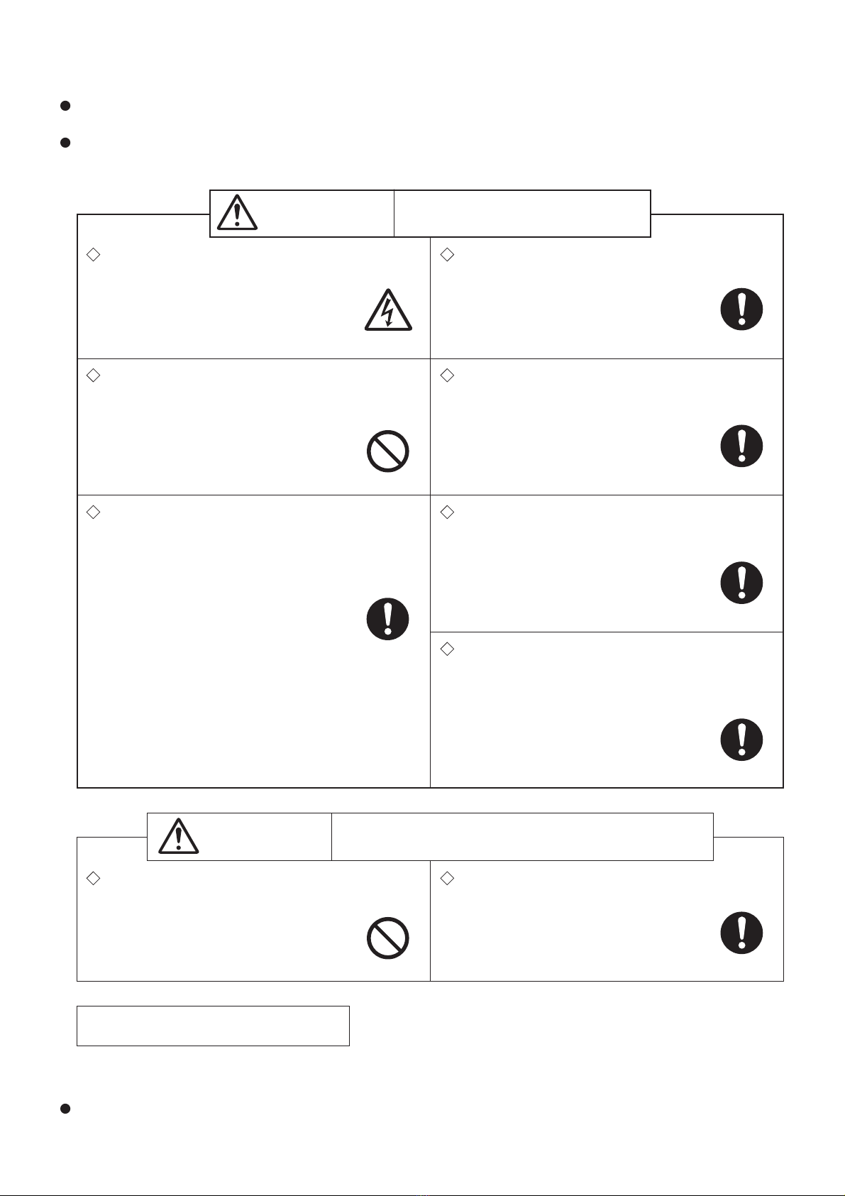
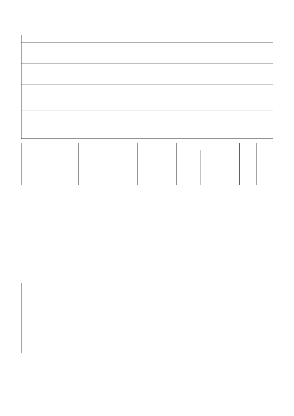
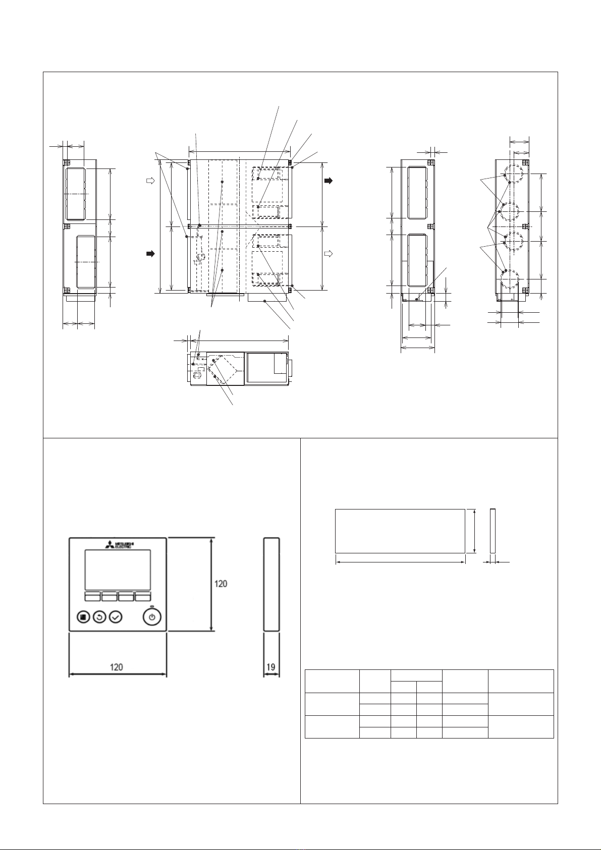
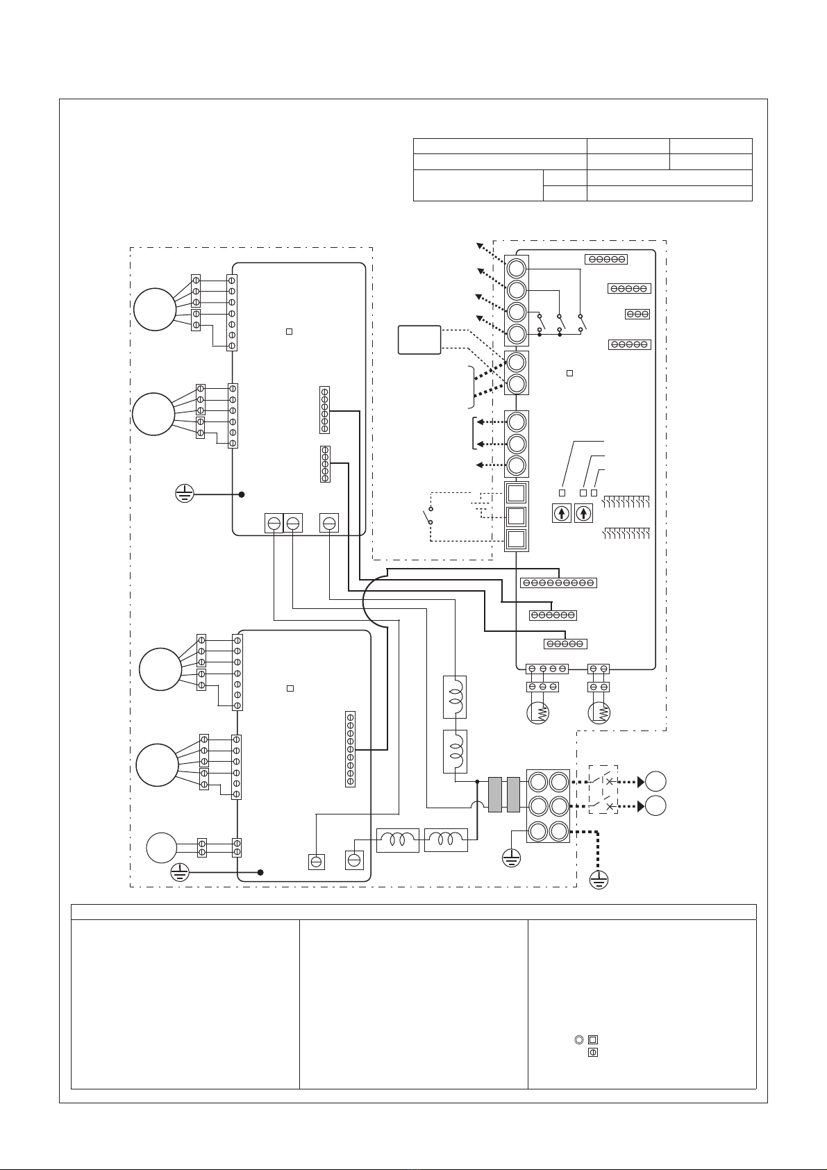
Mitsubishi Electric Lossnay LGH-250RVXT-E User manual
Other Mitsubishi Electric Fan manuals

Mitsubishi Electric
Mitsubishi Electric PAC-SG59SG-E User manual

Mitsubishi Electric
Mitsubishi Electric LGH-100RX3-CAN User manual

Mitsubishi Electric
Mitsubishi Electric LOSSNAY VL-220CZGV-EF User manual

Mitsubishi Electric
Mitsubishi Electric VL-50SR2-E User manual

Mitsubishi Electric
Mitsubishi Electric P-250SB-E User manual

Mitsubishi Electric
Mitsubishi Electric LGH-100RVX-E User manual

Mitsubishi Electric
Mitsubishi Electric LGH-F380RVX2-E User manual

Mitsubishi Electric
Mitsubishi Electric V-251BW-HK User manual

Mitsubishi Electric
Mitsubishi Electric LGH-F300RX5-E1 User manual

Mitsubishi Electric
Mitsubishi Electric LGF-100GX-E User manual

Mitsubishi Electric
Mitsubishi Electric VL-50S2-E User manual

Mitsubishi Electric
Mitsubishi Electric R12A-D Series User manual

Mitsubishi Electric
Mitsubishi Electric P-250F-E User manual

Mitsubishi Electric
Mitsubishi Electric VL-50S2-E User manual

Mitsubishi Electric
Mitsubishi Electric EWF-50FTA40A User manual

Mitsubishi Electric
Mitsubishi Electric Lossnay LGH-F300RX3-E User manual

Mitsubishi Electric
Mitsubishi Electric VL-50ES2-E User manual

Mitsubishi Electric
Mitsubishi Electric Lossnay LGH-35RX5 User manual

Mitsubishi Electric
Mitsubishi Electric VL-50S2-E User manual

Mitsubishi Electric
Mitsubishi Electric LGH-15RVX-E User manual


Popular Fan manuals by other brands

ELTA FANS
ELTA FANS H03VV-F installation guide

Hunter
Hunter 20714 Owner's guide and installation manual

Emerson
Emerson CARRERA VERANDA CF542ORB00 owner's manual

Hunter
Hunter Caraway Owner's guide and installation manual

Panasonic
Panasonic FV-15NLFS1 Service manual

Kompernass
Kompernass KH 1150 operating instructions