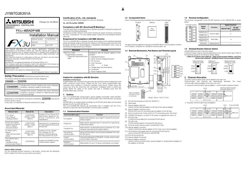
3.5
Settina thestation number
AMITSUBISHI
PROGRAMMABLE
CONTROUERS
MELSEGF
-
2.1 Kev
to
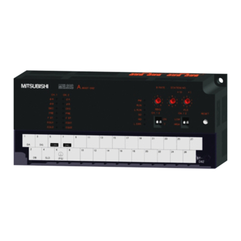
numbereditems on Terminal Lavout diaaram
1.24V
DCtransmissionpower forthe network
IS
supplied bythe
stabilized
powersupply,
2.
Theshleldedtwlsted palrcables connectthe=ON-1
6NTto
the network.The
SDNSDB
terrnmals
ofthepreviousstationshouldbeconnectedtothe
RDNRDB
termlnalsof this station.TheSDNSDB
termlnals of thisstatlon shouldbe connected to the
RDNRDB
termlnalsof the next stabon.
Remove the cover on top of the unit, and set the statlon number (#01 to
#64)
using the rotary
switches. TheRtoN-16NT can occupy only one statlon.Thesame station numberisused forInput
and output.
and
pair
Keep these transmission cables away from powercables.
Do
not allow power cables
transmission cables to share the sameduct.
3.
Use one-point grounding (Class
3
ground,
100
P
or less) for the
shielding
of the twlsted
cable on thesendingor recelvingsldes.
4.
See section
3.6
for use
of
the
ECM
(Emergency
Clear
Mode)
terminal.
-
2.2 Useof crimpstyle terminals
Usecrimp-style terminalsof the indicateddlmenslons. Inch)
or
less
Tighteningtoque:
5
to
8
kgf.crn. Tightenthe terminals M3 (012Inch)
carefully toavoid any malfunctlons.
Firststabonnumberdigit
-
ECM
settingmtch("xl0') connectlon
Connector fornext
extenslon block
Second statlon numberdiglt
setting switch("x1")
JY992D48901A
msmanualcontams text, diagrams and explanabons whlch
vvlll
guide the reader
In
the
correctInstallabon andoperatlon
of
the FXON-I~NTspec~al
functlon
blodc and should be read and understood before attempting
to
Installor usethe
unit
Further Informatton
can
befound
In
the
FX
PROGRAMMING MANUAL and
D(O/FXON
SERIES HARDWARE MANUAL
Enlargedviewof stationnumberselectorswltchLocation of
statton
numberselbngsvvltches
INTRODUCTIONINSTALLATIONNOTESANDUSAGE
I
The
~oN-~~NT
specialfundtonblockconnectsthe mON programmable conirollertothe
3.1
Generalspecifications
.
Use the
~~71p~32-~3
or
A1SJ71
PT32-S3
master unlt or
A2C
CPU
as the master Same
as
those forthe
FXON
base unlt
General specificatlons (excludmg
MELSECNET/MINI-S~
network
as
a
local
stabon, or
as
a remote
I/O
unit ofan
A2C
CPU.
stanon.Connect the \ocalstabon to the master statlonusingtwisted Pair cable. vvlthstand voltage)
-
Item Specification
Withstandvoltage
500
V AC for 1 minute (between groundingtermlnaland
all
the other
8
inputpolntsand
8
outputpolntscan
Numberofoccupledstafions:
1
station
&2
PerformanceSpecifications
(Number of stations:
64
maximum)
e NumberofoccupledInput/output
termmals)
A SenesPCcontalnlng betransmittedon thenetwork.
master
unlt
_----
nm
Cable
Specification
\
I
points:
8
inputpointsand
8
output
Master statlon A171PT3243, AlSJ71PT32-S3. A2C CPU
__
____
-_
po~nts
of the WON
PC
table.(Cross
secbonal
area
shouldbe
0
2
to
0.5
mm
or more dependlng
on
ShleldedMstedparr cable: Fordetailed
speaficatpns.
refer
to
follytng
the
station-to-stabon
distance)
El
Maxlmurn~forsDltion-bstation
RemoteA135PT
tmsmbslon:
100
m
VO
unlt OPB Ml/Pl
~m~r0.2to05mm',1~m~r05mm~ormore
Maxlmum
station-to-station
dlstance
-
3.6
ECM setting
ECM
(EmergencyClear Mode) setting:
When the
MELSECNET/MINI-S3
masterstation stops slgnal COrnmUnlCatlOn
(I/o
refresh) and
IS
In
STOP
mode, the
ECM
terminalconfigurabon can be selected. Setitas shown below.
I
ECM
terminalconnection
Fffmrt
I
~
unconnected ~~~ ~~~~
The data recelvedlust beforea communlcatlon
stoppage
IS
retamed
will reset.
Connectedto 24G terminal The data
IS
not
retained.
All
the FXw-16NT Inputpolnts
-
3.7
AZl
N
PC
The
Rto~-l6NT
enablesblt devlcedatato
be
sentandreceivedbetweenthe
RON
andan
A
Serles
PC
uslng
8
input points and
8
output polnts. Forsuch operanon, the Inputloutputnumbers should
be allocatedon the
WON
PCas shown below:
Connecbon
to
=ON
PC Same
as
VO
extenslon blocks Up to 2unpoweredblocks(indudlng the FXoN-16NT)can
be
connected
to
each powered baseor extension
unlt.
Max.
VO
ofsystem:
128
points.
Occupled stabon
Input
points 1
station.
MELSECNET/MINI-S3
can
support up
to
64
stations
8
pomts:
Allocated
to
FXON
extenston
I/O
numbers.
XnO
to
Xn7
8
polntsoccup~ed
dunng
communicabon (A
to
WON)
output
points
8
points: Allocated
to
extenslonI/O numbers of
FXw,
YmO
to
Ym7
8
points
OCCupled
during
communlcatIon
(WON
to
A)
LED mdlcators POWER. DC, and RUN
indicators
are
on
dunng
normal
operatlon.
POWER
On
when 5V
DC
power issuppl~ed
from
the
FXON
PC (InternalDower
SUDDIVL
Communication direction Allocation
of
inpuVoutput numbers
Description
A
to
FXON
(Input data) XnO-Xn7
The
FXON
wII
only
receivethe data
sent
bv theA Series
PC
which
axrespinds
to
~ts
station
number.
Series PC ISldenbfied
bv
the stabon
FXw
to
A (Output data) YmO-Ym7
The data
sent
bythe
FXoN
to
theA
I
numberofthe
FAON.
I
I
DC
RUN
On
dunngnormalcommunlcatlon
transmlsslon
power supply(external power supply)
On
when
24V
DC power
IS
suppl~ed
from
the
I
n..-knrs
ERR
I
On
when a communlcatlonerrorISdetected.
termlnal connections)
ECM settlng(set
by
causes the master stahon
to
sto~I/Orefresh andacommunlcattonshima!aeoccurs.
Controls the behavlorof the FXm-16NT
If
acommunlcatlonserroroccurs The error
I
I
The
last
datarecelvedby the FXON-~GNT
will
either bekept
oi
iost
I
El
Ir
TERMINALLAYOUTS
I
-
3.8
Examole
of
I/O
allocation
As
wlth other extension blocks, the
I/O
numbers allocated tothe
%ON
system should be
contmuously numberedin
octal
beginningfrom the baseunit. This is showninthe diagram below.
-
3.3
Power supdv specifications
Item Specification
Transmissonpower supply 24V DC +30%
-3596,130
mA
(from
the
stablllzed
power
supply)
Interfacepowersupply 5V
DC
(internal powersupply
from
FXON)
24 and 5V DCare Insulatedlnsldethe FXON-1 6NT
II
!
ASerles PC
AC power supply
Stabilized
24 V DC
power supplyfor
bansmlssion
power
------
XOOO-X027 X030-X037
&
XO50-X077 XbO-Xk
Inputs:
72points.
Total
VO:
56 points.
128points. yoOO-'f017
oU@UtS:
FXON-BCIR FXW-16NT
FXON-~~ER
FXON-16NT
FXON-8EX
FXllN-40MR
-
__
__
~ ~~ ~
YT-Y? Y030;:!7- YT-Yp YO60-YO67
-
3.4
Recommended specification
of
twisted pair cable
1
Rem
Specification
I
&tion (Receivlng stde)
FromSDB terminalof
*
ofnext
station
To SG terminal
of nextstation
,
ToFGterminal
From
SG
terminalof
f
The
FXON-~~NT
block can beconnectedinany position desired. The number ofblocksconnected
to each baseor extension unit (inpuvoutputextensionblock@)
+
FXON-~~NT
block(@)should be
no morethan
2
blocks.
Note: The total numberof inpuvoutput points shouldbe
128
polntsor less.
Cable
type
Shlelded
twlsted
palrcable
Number ofpalrs
2
paws ormore
I
I
Conductor
resistance
(20deg. C)
~~ 88.OQkrn
or
less
1
Capacitance(1
kHz)
60nFkmor less
Charactenstic impedance (100
kHz)
11o+/-1
on
I
