Printed in Japan
Mitutoyo Corporation 1-20-1 Sakado, Takatsu-ku, Kawasaki City, Kanagawa 213-8533
5) Executing/canceling Function Lock function
This product has a Function Lock function which ignores origin
operation in order to avoid accidentally changing the origin. When
function lock is executed, [ ] will appear on the display and operations
other than turning the power on/off, holding/releasing the displayed
value, outputting the displayed value, and canceling the Function Lock
function will be disabled.
●Executing Function Lock function
1Press and hold the [MODE] key to enter parameter setting mode.
⇨Shifts to parameter setting mode.
2Selecting the parameter item to set
1 Press the [MODE] key until [Fn-Loc] is displayed.
2 Press the [SET] key.
⇨Function Lock function can be set.
3Setting the function lock function
1 Press the [MODE] key and select execute (on).
2 Press the [SET] key.
⇨Settings are confirmed; shifts to next parameter item.
(Proceed to step 2in "1) Setting counting direction".)
Tips
• The Function Lock function is executed as soon as parameter
setting is confirmed and the product returns to measurement mode.
•
To set an item for which the function has been locked, first cancel
the Function Lock function
.
●Canceling Function Lock function
1Press and hold the [MODE] key to enter parameter setting mode.
⇨Shifts to parameter setting mode [Fn-Loc].
2Press the [SET] key to confirm the parameter item (function lock)
to set.
⇨Function Lock function can be set.
3Setting the function lock function
1 Press the [MODE] key and select cancel (oFF).
2 Press the [SET] key.
⇨Settings are confirmed; shifts to next parameter item.
(Proceed to step 2in "1) Setting counting direction".)
Key icon operation
=
> 2 s
=
< 1 s
11. Precautions After Use
• When cleaning, wipe this product with a soft cloth moistened with diluted neutral detergent. Do not
use an organic solvent such as thinner, which may cause the product to deform or malfunction.
•
Dirt on the spindle may lead to malfunction. Clean with a cloth moistened with alcohol, etc. before use.
• Do not lubricate the spindle with lubricating oil, etc.
• If the product is to be out of use for 3 months or more, remove the battery before storage. Liquid
leakage from the battery may damage the product.
• Do not store the product in a place with a high temperature or humidity, or a lot of dust or oil mist.
1
3
2
2
3
1
2
3
3
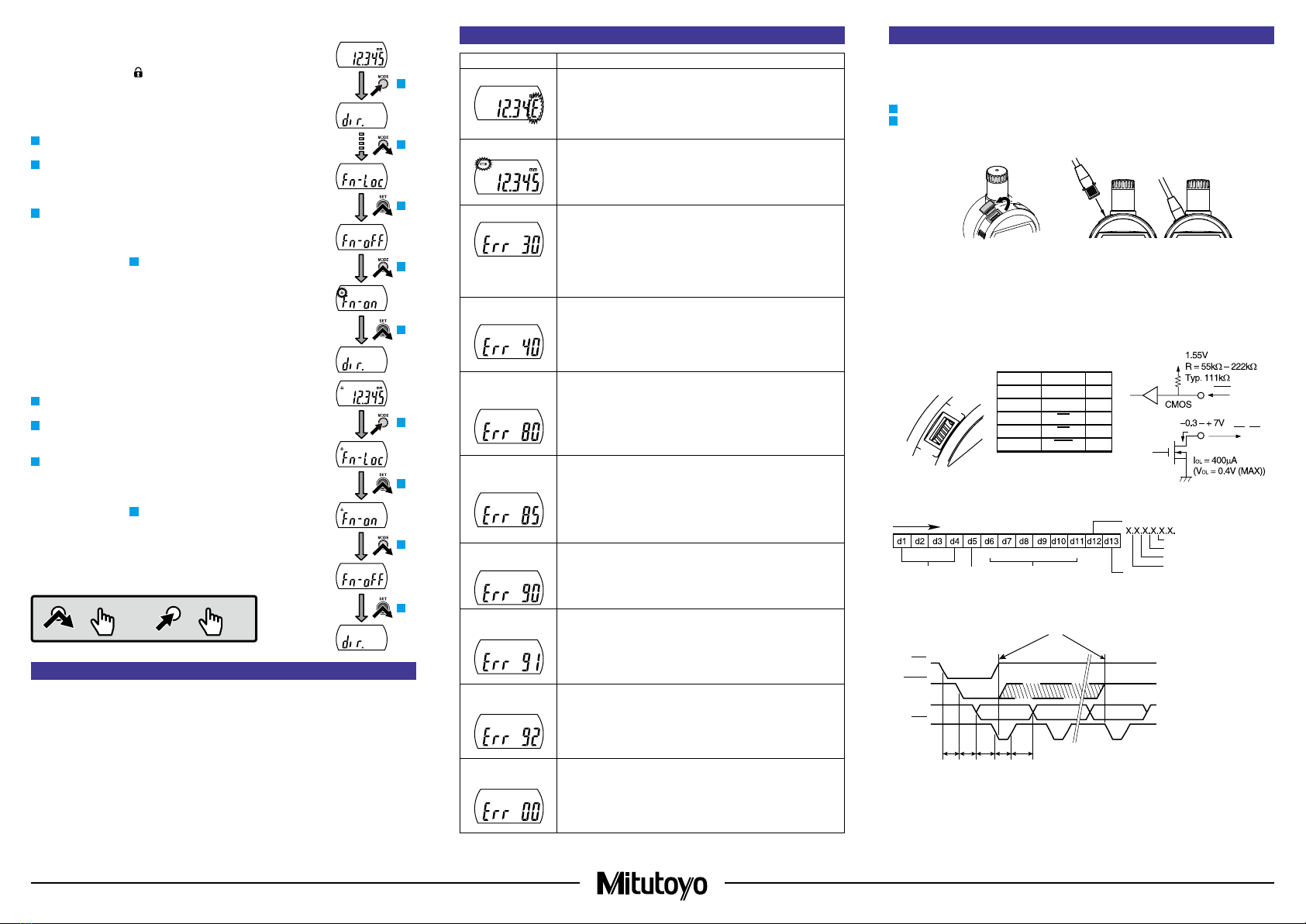
12. Error Displays and Countermeasures
Error Display Causes and Countermeasures
ABS Synthesis Error Although this may be momentarily displayed while the spindle is
moving, it is a normal artifact of internal processing. If it occurs while
the spindle is not moving, the internal sensor has failed.
In this case, repair is required: contact your dealer or agent or our
sales office.
Low Battery Voltage
Battery is depleted.
Replace with a new battery.
Display Overflow
The measured value exceeds the number of digits that can be displayed.
• In ABS, press the [SET] key to enter the origin setting and reset (re-
preset) the origin.
•
I
n INC, press the [SET] key at the appropriate position and set to zero.
• Press and hold the [MODE] key to enter parameter setting mode
and change the resolution to an appropriate value. (0.001 mm or
0.00005 in models only)
Sensor Contamination
Detection Error A sudden change in temperature may create condensation on the
detector, or it may be contaminated by other sources.
• Turn the power off and allow the product to adapt to the temperature
for about 2 hours.
• If it does not recover after adapting to the temperature, repair is
required: contact your dealer or agent or our sales office.
Preset Value Setting
Error (Normal
Measurement)
The preset value set for normal measurement exceeds the number of
digits that can be displayed.
• Press and hold the [SET] key to return to preset value settings, and
then reset to an appropriate value.
• Press the [SET] key to return to measurement mode, and then
switch to an appropriate resolution in parameter setting mode.
(0.001 mm or 0.00005 in models only)
Preset Value Setting
Error (Calculation
Measurement)
The preset value set for calculation measurement exceeds the
number of digits that can be displayed.
• Press and hold the [SET] key to return to preset value settings, and
then reset to an appropriate value.
• Press the [SET] key to return to measurement mode, and then
switch to an appropriate resolution in parameter setting mode.
(0.001 mm or 0.00005 in models only)
Tolerance Limit Value
Setting Error The upper limit is set below the lower limit.
• Press the [SET] key to return to the tolerance limit value settings,
and then reset so that the upper limit is above the lower limit.
Upper Limit Setting
Error The upper limit exceeds the number of digits that can be displayed.
• Press and hold the [SET] key to return to upper limit settings, and
then reset to an appropriate value.
• Press the [SET] key twice to enter resolution settings, and then switch
to an appropriate resolution. (0.001 mm or 0.00005 in models only)
Lower Limit Setting
Error The lower limit exceeds the number of digits that can be displayed.
• Press and hold the [SET] key to return to lower limit settings, and
then reset to an appropriate value.
• Press the [SET] key to enter resolution settings, and then switch to
an appropriate resolution. (0.001 mm or 0.00005 in models only)
Calculation Coefficient
Setting Error The calculation coefficient is set to 0.0000.
• Press and hold the [SET] key to return to calculation coefficient
settings, and then reset the calculation coefficient to a value other
than 0.0000.
13. Output Function
1) Externally outputting the displayed value
The product can be connected to an optional external display, external printer, PC, etc. The
displayed value can be output to a device supporting Digimatic output format by connecting the
product and the external device with a connection cable (optional).
1Press the [ON/OFF] key to turn off the product.
2Connecting the product and the external device
1. Remove the cap of the output connector of the product.
2. Connect the product and the external device with a connection cable.
12
Cap
Connection
cable
Tips
• Two types of connection cables (optional), part No. 905338 (1 m) and part No. 905409 (2 m),
are available for this product.
• When connecting a connection cable, pay attention to the connector direction as you insert it.
• Store the removed cap to prevent loss.
• Always install the cap if a connection cable is not used.
2) Output connector
3) Output data format
(1) Output order
(2) All "F"
(3) Sign
(4)
Measured value
(5)
Decimal point
(6) Unit
4) Timing chart
10 ms ≤ t1 < 150 ms
0.1 ms ≤ t2 < 0.2 ms
0.1 ms ≤ t3 < 0.2 ms
0.05 ms ≤ t4 < 0.2 ms
t5 depends on the device
being used.
*1 Keep REQ at Low until CK is output.
Return it to High before the final CK output is completed (52nd bit).
REQ
DATA, CK, RD
(1)
(5)
Pin No. Signal I/O
(1) GND -
(2) DATA O
(3) CK O
(4) RD O
(5) REQ I
・Input
・Output
MSD LSD
(2) (4)
(3)
+: 0(0000)
2(0100
3(1100)
4(0010
5(1010
(6)
mm:0(0000)
RD
REQ
CK
t5 t1 t2 t3 t4
1bit 2bit 52bit