Mitutoyo Corporation 20-1, Sakado 1-Chome, Takatsu-ku, Kawasaki-shi, Kanagawa 213-8533, Japan Date of publication: October 1, 2021
Printed in Japan
1
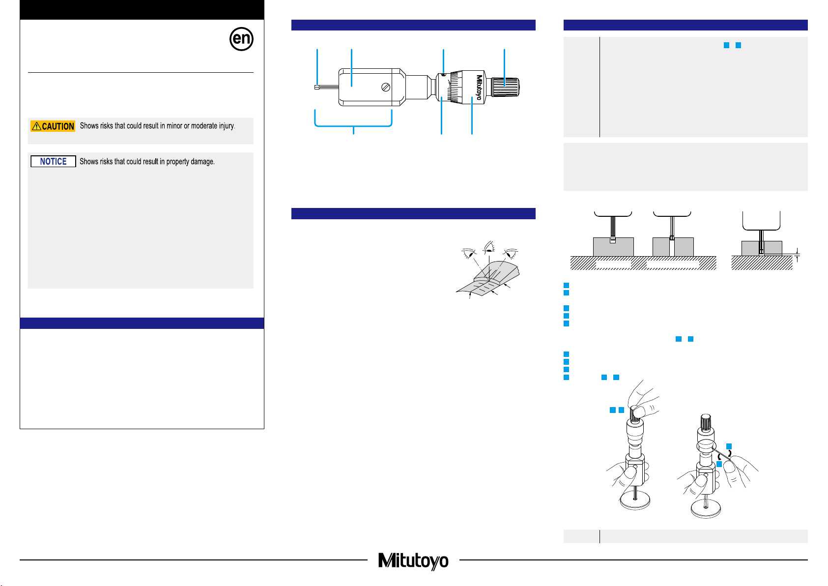
1. Names of Components
①
②
③ ④ ⑤
⑦ ⑥
①Measuring head
②Contact point
③Main body cover section
④Setting screw
⑤Ratchet
⑥Thimble
⑦Sleeve
2. Precautions for Use
■Parallax
• Due to the way this product is constructed, the plane of the reference
line on the sleeve is not on the same plane as the graduation line on the
thimble, so the point where the two lines meet will be viewed differently
depending on the position of your eyes. When reading measured
values, do so perpendicular from the point where the reference line on
the sleeve meets the graduation line on the thimble (see the gure on
the right).
• If you are looking from a different direction (as in the gure on the right),
be aware that there will be a parallax of roughly 2 μm.
■Measuring Force
• When measuring, use the ratchet to ensure a consistent measuring force.
• To achieve an appropriate measuring force, make light contact between the measurement surfaces and the workpiece,
and then turn the ratchet about ve to six times with your ngers. Note that excessive measuring force may cause
errors.
■Precautions and Cleaning after Use
• After use, check that none of the parts are damaged, and clean the entire product, including the sliding part of the
contact points, with a soft, lint-free cloth.
• If oil, cutting uid, or other uids harden on the product or if dirt is difcult to remove, put some volatile cleaning liquid
(such as cleaning alcohol) on a soft, lint-free cloth, and use that to clean the product.
• After use, apply some Micrometer Oil (Part No. 207000) to prevent rust from forming on the contact points.
• If the product is used in places exposed to water-based cutting uid, always apply anti-rust treatment after cleaning.
• If Micrometer Oil is not available and you must use a commercially available product, we recommend using an anti-rust
agent with low viscosity.
3. Reference Point Setting
IMPORTANT
• When measuring, be sure to follow the procedure in steps 1to 9 below to conrm and set the
reference point.
• When setting the reference point for this product, make sure to use a calibrated gage (setting ring,
etc.).
• Remove any dirt or oil from the measurement surfaces of the gage and product prior to setting the
reference point.
• Due to the product mechanism, the measured value will differ depending on whether the entire
surface of the contact points or only their edges are used for measurement. Use the same
conditions as when measuring to set the reference point.
• Use the same orientation and conditions as when measuring to set the reference point.
(See Figure 1 if you are using the edges of the contact points to measure a blind hole.)
Tips
Do not let the bottom of the measuring head touch anything when setting the reference point or measuring (Figure 2).
If the bottom touches anything when you are measuring a workpiece, the inclination of the surface that the bottom
touches could cause the contact points not to touch parallel to the workpiece, which can lead to measurement
errors.
Figure 1 Figure 2
Workpiece Reference point setting
1Remove any dirt or dust from the measurement surfaces of the calibration gage and the product.
2Set a measuring length slightly less than the size of the gage by rotating the thimble of the product, and then slowly
insert the product into the gage.
3Bring the contact points gently into contact with the inside of the gage by rotating the thimble with the ratchet.
4 Apply the proper measuring force by rotating the ratchet ve to six times.
5Read the measured value, and if the reading matches the size of the gage, then the reference point setting is
complete.
If the reading is different, perform the work in steps 6to 9again. (Repeat until the reference point setting is
complete.)
6Loosen the setting screw with the supplied hex wrench.
7Align the reference line on the sleeve with the proper indicated value by slightly rotating the sleeve.
8Fix the sleeve by tightening the setting screw with the supplied hex wrench.
9Perform steps 1to 5again, and check whether the reading matches the size of the gage.
IMPORTANT
Do not move the product after it has been inserted until the reference point setting is complete.
34
6
8
Safety Precautions
To ensure operator safety, use this product according to the directions, functions and specications given in this
User's Manual.
Use under other conditions may compromise safety.
Always handle the sharp measuring faces of this product with care to avoid injury.
• Do not disassemble or modify. Doing so will void the warranty.
• Do not use or store the product in a place with sudden temperature changes. Also, before using the
product, allow it to acclimate to room temperature.
• Do not store the product in a place with high humidity or a lot of dust.
• Do not use the product in a place where it may contact water, etc.
• Do not apply excessive force or subject the product to sudden impacts such as dropping.
• If oil or cutting chips become attached to the sliding portion of the contact points, a malfunction may
result. Wipe off any oil or cutting chips after use.
• Use a soft, lint-free cloth to wipe dirt off of the product. Do not use detergents or organic solvents such
as thinner.
• Do not write on the product, such as numbers, with an electric pen.
• Do not move or hang this product while the measuring head is set on a workpiece.
• Use the product only with the supplied contact points.
• Do not pull out the contact points. Otherwise damage may result.
Holtest
(Two-Point Internal Micrometer)
D/E
User's Manual No. 99MAA023A
Contents
1. Names of Components .............................................................................................................................. Page 1
2.Precautions for Use ................................................................................................................................... Page 1
3.Reference Point Setting............................................................................................................................. Page 1
4.Measurement Method................................................................................................................................ Page 2
5.How to Read Graduations ......................................................................................................................... Page 2
6. Specications............................................................................................................................................. Page 2
7. Paid Maintenance ...................................................................................................................................... Page 2
NG
OK
NG
Reference line
Sleeve
Thimble


