manuals.online logo
Brands
  1. Home
  2. •
  3. Brands
  4. •
  5. Mitutoyo
  6. •
  7. Measuring Instrument
  8. •
  9. Mitutoyo CG-S10A User manual

Mitutoyo CG-S10A User manual

Printed in Japan
Mitutoyo Corporation, 1-20-1 Sakado, Takatsu-ku, Kawasaki City, Kanagawa 213-8533, Japan
Date of publication: April 10, 2018
1.  Names of Components
②
①
③
④
⑤
⑩
⑨
⑥
⑧
⑦
⑪
⑫
CGF-X
①Clamp screw
②Indicator holder
③Grip
④Pipe (outer sleeve)
⑤Measuring head
⑥Supporting nut
⑦Anvil
⑧Adjustment washer
⑨Guide
⑩Contact point (contact rod)
⑪Guide stopper screw
⑫Contact rod holder
Tips
No guide (guide plate) is provided with CG-S10A.
2.  Preparation for Measurement
1) Setup
NOTICE
• Conrm that the measuring head or screw is not loosened before use.
• Do not insert, remove, or turn the indicator with the clamp screw tightened, as it will lead to
breakage.
• If the insertion hole of the indicator holder is accidentally deformed, correct it by inserting a
ø8 mm rod for the metric type and a ø9.53 mm rod for the inch type.
• Secure xation may be impossible when the indicator or the indicator holder insertion hole or
the clamp screw is dirty. Clean them in advance.
1
3
Dial protection cover
Clamp screw
1Loosen the clamp screw and insert the indicator into the indicator holder.
2 Tighten the clamp screw to x the indicator.
Tips
Firm tightening is possible by turning with an object such as a coin inserted in the groove on the
clamp screw head.
3When required, attach a dial protection cover (optional depending on models).
4For models with a measurement range of 160 mm or more, the direction of the guide unit must
be switched.
1. Push the guide until it hits the end lightly.
2. Turn 90 degrees clockwise.
3. Let go.
⇨The guide returns to the reference point position, and the product is ready for measurement.
1
2
Safety Precautions
To ensure operator safety, use this product in conformance with the directions, functions
and specications given in this User’s Manual.
Use under other conditions may compromise safety.
NOTICE
• Do not disassemble or modify. This may cause damage.
•
Do not use or store the product in a place with sudden temperature changes. Adapt the
product to room temperature before use.
•
Do not store the product in a place with high humidity or a lot of dust.
• Do not apply impact or excessive force to this product.
•
Be sure to perform reference point setting before measurement.
• Remove dust, cutting chips, etc. before and after use.
• After use, clean and perform anti-rust treatment for the body, anvils, adjustment washers,
etc. Insufcient cleaning may cause accuracy or operation to suffer.
•
For periodic calibration or precision measurement, wear thick gloves in order to reduce
changes in the indicated value caused by the transmission of body temperature.
•
Indicators with rubber bellows such as waterproof dial gages cannot be used.
Tips
The bore gage is a comparator. It will not function as a measuring instrument if used alone.
An indicator such as a dial gage and a reference gage such as a set ring or micrometer are
required to use the product.
Bore Gage
User's Manual No.99MAJ005A
CG-SA CG-AXCGB-X CGF-X
CGM-X
Model/Code No. List
Model Code No.
CG-S10A 511-209
CG-S18A 511-201
CG-S.4"A 511-214
CG-S.7"A 511-205
CGB-35X 511-761
CGB-60X 511-762
CGB-150X 511-763
CGB-160X 511-764
CGB-1.4"X 511-781
CGB-2.5"X 511-782
Model Code No.
CGB-6"X 511-783
CGB-6.5"X 511-784
CG-35AX 511-701
CG-60AX 511-702
CG-150AX 511-703
CG-160AX 511-704
CG-250AX 511-705
CG-400AX 511-706
CG-1.4"AX 511-731
CG-2.5"AX 511-732
Model Code No.
CG-6"AX 511-733
CG-6.5"AX 511-734
CG-10"AX 511-735
CG-16"AX 511-736
CGF-35X 511-415
CGF-60X 511-416
CGF-150X 511-417
CGF-1.4"X 511-418
CGF-2.4"X 511-419
CGF-6"X 511-420
Model Code No.
CGM-100X 511-803
CGM-160X 511-804
CGM-250X 511-805
CGM-400X 511-806
CGM-600X 511-807
CGM-800X 511-808
CGM-4"X 511-833
CGM-6.4"X 511-834
CGM-10"X 511-835
CGM-16"X 511-836
Model Code No.
CGM-24"X 511-837
CGM-32"X 511-838
en
Printed in Japan
Mitutoyo Corporation, 1-20-1 Sakado, Takatsu-ku, Kawasaki City, Kanagawa 213-8533, Japan
Tips
Use a sub-anvil as well when the micrometer head only is insufcient for the required adjustment
range.
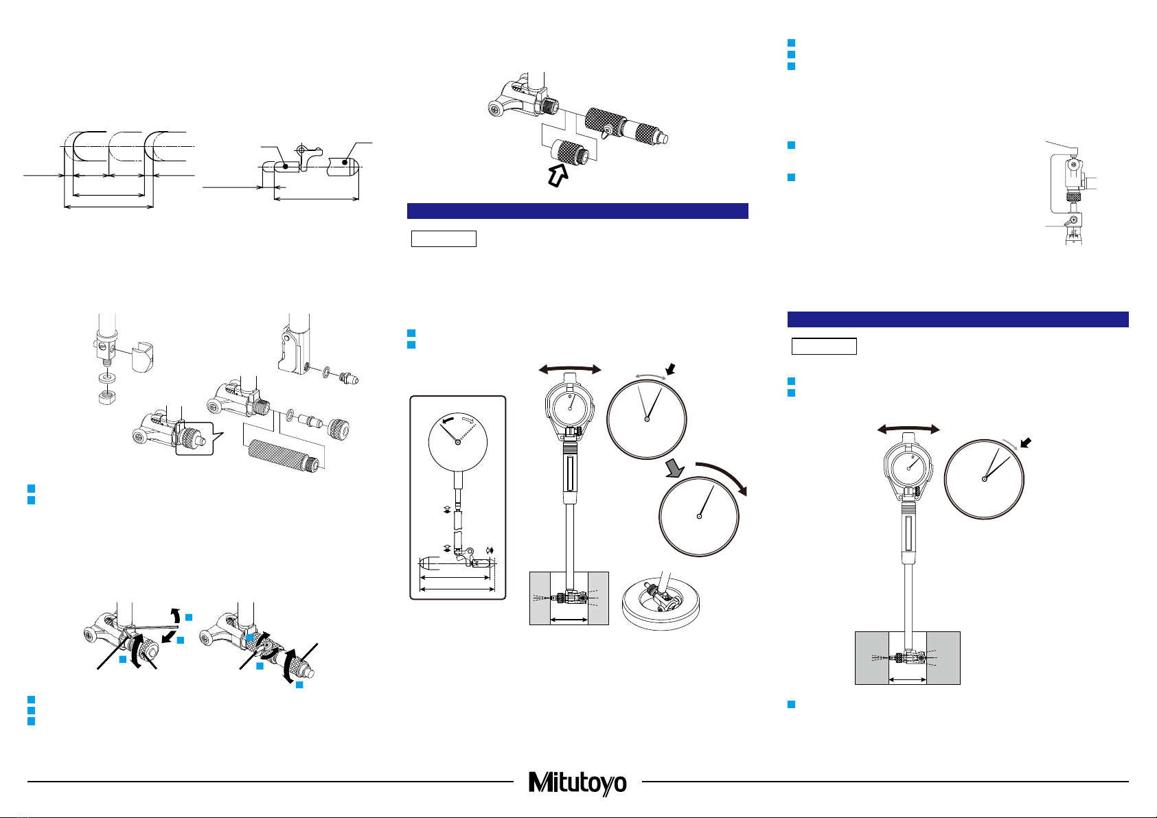
3.  Reference Point Setting
NOTICE
• A reference gage is required for reference point setting.
• Dirt on the reference gage may lead to an error. Clean before reference point setting.
• Be sure to set the reference point before measurement and after measured dimension setting.
Even during continuous measurement, set the reference point as often as possible.
1) Reference point setting with a set ring or cylindrical master gage
1Insert the bore gage into the reference gage (set ring or cylindrical master gage).
2Oscillate the bore gage. The reference point is where the contact point is pushed deepest.
0
10
20
30
0
10
20
30
0
A
B
B
A
60.00
Tips
• Setting the indicator to the reference point.
• Turn the bezel when the indicator is a dial gage.
• Perform presetting when the indicator is a Digimatic indicator.
• When inserting the bore gage into a reference gage, insert the contact point/guide side rst.
After that, insert the anvil side while pressing the guide to the reference gage.
2) Reference point setting with outside micrometer and gauge block
1
Measure the gauge block corresponding to the reference dimension by inserting it into the micrometer.
2Clamp the micrometer and then remove the gauge block.
3Insert the bore gage instead into the micrometer, and then oscillate the bore gage. The
reference point is where the contact point is pushed deepest.
3) Reference point setting with outside micrometer only
Notices
Do not clamp the micrometer.
1 Fix the micrometer vertically with the head (spindle) portion
downward and align the opening of the measuring surfaces
to the reference dimension.
2Insert the bore gage to the measuring surfaces of the
micrometer and then oscillate the bore gage. The reference
point is where the contact point is pushed deepest.
Tips
• Reference point setting with the outside micrometer requires expertise, since centripetal effects
by the guides cannot be utilized.
• Reference point setting can be performed in the same way as with an outside micrometer even
with another reference gage (gauge block, height master, bore gage checker).
4.  Measurement Method
NOTICE
Dirt on the workpiece may lead to an error. Clean before measurement.
1Insert the bore gage into the workpiece to be measured.
2Oscillate the bore gage and read the indicated value. If the indicator is a dial gage, read the
value when the needle swings widest clockwise.
0.07 mm
0
59.93
10
20
30
3Calculate the measured value by adding the read value (difference) to the dimension of the
reference gage.
Tips
When inserting the bore gage into the workpiece to be measured, insert the contact point/guide
side rst. After that, insert the anvil side while pressing the guide to the workpiece.
2) Adjusting the nominal size
Adjust the nominal size according to the dimensions to be measured by attaching an anvil,
adjustment washer, or sub-anvil, or adjusting the micrometer head.
We recommend using a central value of the measured dimensions as nominal size L.
For instance, if the measured dimensions are 100 ±0.05 mm, the nominal size is set to 100 mm.
Similarly, if the measured dimensions are 100.5 +0.02/-0.08 mm, nominal size L should ideally be
set to 100.47 mm. However, except for CGM-X, settings in 0.01 mm increments are not possible.
Therefore, set to 100.5 mm, the nearest possible value to the central value.
B
A
L
Po
Po
S
R
R/2R/2
0.1 mm + R/2
(0.004 in + R/2)
0.1 mm
(0.004 in)
0.1 mm
(0.004 in)
A:
Contact point
B: Anvil
L: Nominal size (length from the anvil tip to P0 which is the center of effective measurement range)
R:
Effective measurement range
S:
Movable range
■ Adjusting the nominal size with anvils, adjustment washers, or sub-anvils.
CG-S10A,
CG-S.4”A
CG-S18A, CG-S.7”A,
CG-35AX, CG-1.4”AX,
CGB-35X, CGB-1.4”X,
CGF-35X - CGF-150X,
CGF-1.4"X - CGF-6"X
CG-60AX - CG-400AX,
CG-2.5”AX - CG-16”AX,
CGB-60X - CGB-160X,
CGB-2.5”X - CGB-6.5”X
1Select an anvil, adjustment washers, etc. according to the measured dimensions.
2Mount securely, making sure there is no looseness or play.
Tips
• If attaching multiple adjustment washers, attach as few as possible.
• Except for models where an anvil is xed with a supporting nut, use the provided wrench when
attaching or removing the anvil.
■ Adjusting the nominal size with micrometer head
1
3
CGM-X
1
3
2
2
1
3
Hex socket head set screw Thimble
Thimble
Clamp
1 Turn the hex socket head set screw or clamp to release the micrometer head.
2Turn the thimble to adjust the length of the micrometer head.
3 Turn the hex socket head set screw or clamp to x the micrometer head.
Printed in Japan
Mitutoyo Corporation, 1-20-1 Sakado, Takatsu-ku, Kawasaki City, Kanagawa 213-8533, Japan
1 Remove the measuring head by turning it while the pipe is xed with the wrench provided with the
extension rod.
1
2 Screw in the extension rod to the pipe.
3 Screw in the measuring head while the extension rod is xed with the wrench.
32
Tips
If the measuring head is hard to rotate manually, turn while holding with a tool such as
combination pliers. While doing so, wrap the measuring head with a soft cloth or use combination
pliers with a resin measuring head in order to prevent damage.
7.  Specications
• Operation environment: Temperature 0°C to 40°C, humidity 30% to 70%
• Storage environment: Temperature -10°C to 50°C, humidity 30% to 70%
8.  Off-Site Repairs (Subject to Charge)
Off-site repair (subject to charge) is required in the case of the following malfunctions. Contact your
nearest dealer or our sales ofce.
• Poor accuracy
• Wear on contact point or guide
• Contact point malfunction
• If the product is repaired by a party other than Mitutoyo, its performance cannot be guaranteed.
5.  Maintenance
• Clean the exterior with a soft, dry cloth or a cloth slightly moistened with neutral detergent or
alcohol. Do not use other organic solvents (thinner, benzine, etc.) for resin components.
• If the inside of the measuring head is dirty, disassemble and wash it. However, the measuring
head of CG-SA cannot be disassembled. Wash it by immersing it in alcohol.
• To disassemble the measuring head, turn the guide stopper screw or contact rod holder
anticlockwise with commercially available snap ring pliers or small monkey wrench.
CGF-X
Hole diameter on the guide stopper
screw
Models with measurement range of 35 mm or less: ø1 mm
Others: ø1.5 mm
Width across ats of contact rod holder 4.2 mm
• Models with measurement range of more than 160 mm contain a ball and spring to stop guide
rotation. Note that the ball may pop out when you remove the guide.
• When you attach the removed measuring head again, tighten the measuring head securely while
the pipe is held with priers which do not cause damage to the pipe.
• When the product will be out of use for a long period of time, clean and perform anti-rust
treatment, and then store it in a place without condensation. When using the product again, verify
the accuracy and operation of the bore gage and indicator.
• The performance of the bore gage is strongly inuenced by usage and storage conditions. We
recommend stipulating a maintenance cycle in-house according to usage frequency, environment,
storage method, etc., and inspecting the product periodically.
6.  Extension Rod (Optional)
When measuring deep holes which cannot be measured with a standard bore gage, the measurement
depth can be extended by connecting an extension rod (CG-AX, CGB-X, CGM-X, and CGF-X only).
NOTICE
• Do not connect 2 or more extension rods.
• When an 500 mm or more extension rod is connected, use the product vertically.
• When an extension rod is connected, accuracy may change due to deection, etc. We
recommend performing reference point setting in the same orientation as measurement, in
order to reduce effects on accuracy.
• Securely tighten screws without looseness. Insufcient tightening may lead to breakage, poor
accuracy, malfunction or injury due to falling components.
• Hold the front and back of the measuring head of CGF-X since it may deform if held by the
guide. Be sure not to grasp the contact point (contact rod).

This manual suits for next models

41

Other Mitutoyo Measuring Instrument manuals

Mitutoyo LGF-110L-B User manual

Mitutoyo

Mitutoyo LGF-110L-B User manual

Mitutoyo ID-C User manual

Mitutoyo

Mitutoyo ID-C User manual

Mitutoyo 700 Series User manual

Mitutoyo

Mitutoyo 700 Series User manual

Mitutoyo BMB-K User manual

Mitutoyo

Mitutoyo BMB-K User manual

Mitutoyo QM-Height Series User manual

Mitutoyo

Mitutoyo QM-Height Series User manual

Mitutoyo DMS User manual

Mitutoyo

Mitutoyo DMS User manual

Mitutoyo QM-Height QMH-350AX User manual

Mitutoyo

Mitutoyo QM-Height QMH-350AX User manual

Mitutoyo IT-012U User manual

Mitutoyo

Mitutoyo IT-012U User manual

Mitutoyo QM-Height User manual

Mitutoyo

Mitutoyo QM-Height User manual

Mitutoyo SJ-210 User manual

Mitutoyo

Mitutoyo SJ-210 User manual

Mitutoyo MDH User manual

Mitutoyo

Mitutoyo MDH User manual

Mitutoyo SURFTEST SV-3100 User manual

Mitutoyo

Mitutoyo SURFTEST SV-3100 User manual

Mitutoyo BOREMATIC User manual

Mitutoyo

Mitutoyo BOREMATIC User manual

Mitutoyo HDS-H30C User manual

Mitutoyo

Mitutoyo HDS-H30C User manual

Mitutoyo 7210 User manual

Mitutoyo

Mitutoyo 7210 User manual

Mitutoyo ID-SX User manual

Mitutoyo

Mitutoyo ID-SX User manual

Mitutoyo IMZ-MJ User manual

Mitutoyo

Mitutoyo IMZ-MJ User manual

Mitutoyo QuantuMike MDE-MX User manual

Mitutoyo

Mitutoyo QuantuMike MDE-MX User manual

Mitutoyo QM-Data 300 User manual

Mitutoyo

Mitutoyo QM-Data 300 User manual

Mitutoyo 209 Series User manual

Mitutoyo

Mitutoyo 209 Series User manual

Mitutoyo 530-101 User manual

Mitutoyo

Mitutoyo 530-101 User manual

Mitutoyo Litematic VL-50A User manual

Mitutoyo

Mitutoyo Litematic VL-50A User manual

Mitutoyo ID-F125 User manual

Mitutoyo

Mitutoyo ID-F125 User manual

Mitutoyo 500-150-30 User manual

Mitutoyo

Mitutoyo 500-150-30 User manual

Popular Measuring Instrument manuals by other brands

Intellimeter Vision Series user manual

Intellimeter

Intellimeter Vision Series user manual

Blue-White F-460 instruction manual

Blue-White

Blue-White F-460 instruction manual

Vega VEGACAL 65 operating instructions

Vega

Vega VEGACAL 65 operating instructions

LaMotte 1200-CL manual

LaMotte

LaMotte 1200-CL manual

Pambry Listen Ear quick start guide

Pambry

Pambry Listen Ear quick start guide

PCE Health and Fitness PCE-SLM 10 user manual

PCE Health and Fitness

PCE Health and Fitness PCE-SLM 10 user manual

LUDLUM 2241 quick start guide

LUDLUM

LUDLUM 2241 quick start guide

OHAUS i-DT33P instruction manual

OHAUS

OHAUS i-DT33P instruction manual

ABB IM/SM3000 user guide

ABB

ABB IM/SM3000 user guide

FASANO TOOLS CAT III 300V manual

FASANO TOOLS

FASANO TOOLS CAT III 300V manual

Electro Industries/GaugeTech Shark 100 Installation and operation manual

Electro Industries/GaugeTech

Electro Industries/GaugeTech Shark 100 Installation and operation manual

Rhopoint Instruments Optimap PSD 3 manual

Rhopoint Instruments

Rhopoint Instruments Optimap PSD 3 manual

Nokeval Solid-Sky-2Pro-DIO-RS485 manual

Nokeval

Nokeval Solid-Sky-2Pro-DIO-RS485 manual

PPE Fowler 52-224 Series instructions

PPE

PPE Fowler 52-224 Series instructions

Cirris Signature 1000R+ user guide

Cirris

Cirris Signature 1000R+ user guide

Sper scientific 850001 instruction manual

Sper scientific

Sper scientific 850001 instruction manual

Hanna Instruments Checker HI701 user manual

Hanna Instruments

Hanna Instruments Checker HI701 user manual

Yamaha Tenor owner's manual

Yamaha

Yamaha Tenor owner's manual

manuals.online logo
manuals.online logoBrands
  • About & Mission
  • Contact us
  • Privacy Policy
  • Terms and Conditions

Copyright 2025 Manuals.Online. All Rights Reserved.