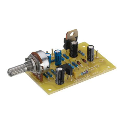
Microphone Preamplifier Module
Please read these operating instructions carefully prior to
operating the unit and keep them for later reference.
1 Applications
Via the module MPA-1 a microphone can be connected to
the Line input of an audio unit. The microphone pream-
plifier can be constructed with a corresponding voltage
supply as an individual unit or placed as a module into an
audio unit (e. g. amplifier, mixer, etc.). For the operation a
DC voltage of 12–40 V is necessary. The current con-
sumption is 6 mA.
2 Safety Notes
GThe module has been constructed according to the
EMC directive 2004/108/EC (EMC = electromagnetic
compatibility). To conform to this directive also while in
operation, the module must be placed into a shielded
housing, and the input as well as the output must be
connected via shielded cables. If the EMC directive is
not complied with, the declaration of conformity does
no longer apply.
GThe module is only suitable for indoor use. Protect it
against dripping water and splash water, high air
humidity, and heat (admissible ambient temperature
range 0 – 40 °C).
GNo guarantee claims for the module and no liability for
any resulting personal damage or material damage will
be accepted if the module is used for other purposes
than originally intended, if it is not correctly connected,
overloaded, or not repaired by authorized, skilled per-
sonnel.
3 Connection
The complete connection is shown in fig. 1:
INPUT . . signal input, connection for the microphone
. . . . . ground for the microphone
OUTPUT output
. . . . . ground for the output
+U . . . . . operating voltage 12–40 V
. . . . . ground for the operating voltage
4 Setting into Operation
After connecting the supply voltage, the microphone pre-
amplifier is ready for operation. Adjust the microphone
volume with the built-in control. Thereby the following unit
must not be overdriven.
5 Specifications
Frequency range: . . . . . . . . . . . 20–15 000 Hz,
-
0.5 dB
15–20 000 Hz,
-
3dB
Input sensitivity: . . . . . . . . . . . . 2 mV with 0 dB at the
output
Input impedance: . . . . . . . . . . . 200 Ω–10 kΩ
Output voltage: . . . . . . . . . . . . . 7 V max./1 kΩ
Gain: . . . . . . . . . . . . . . . . . . . . . 52 dB
S/N ratio: . . . . . . . . . . . . . . . . . > 65 dB
THD: . . . . . . . . . . . . . . . . . . . . . < 0.05 %
Noise voltage: . . . . . . . . . . . . . . 0.5 μV
Power supply: . . . . . . . . . . . . . . 12–40 V /6 mA
Permissible
operating temperature: . . . . . . . 0–40 °C
Dimensions
w/o axle (W × H × D): . . . . . . . . 40 × 25 × 60 mm
Weight: . . . . . . . . . . . . . . . . . . . 30 g
Subject to technical modification.
If the module is to be put out of operation de-
finitively, take it to a local recycling plant for a
disposal which is not harmful to the environ-
ment.
Mikrofonvorverstärker-
Baustein
Bitte lesen Sie diese Anleitung vor dem Betrieb gründlich
durch und heben Sie sie für ein späteres Nachlesen auf.
1 Verwendungsmöglichkeiten
Über den Baustein MPA-1 lässt sich ein Mikrofon an
einen Line-Eingang eines Audiogerätes anschließen. Der
Mikrofonvorverstärker kann mit einer entsprechenden
Spannungsversorgung als Einzelgerät aufgebaut oder
als Modul in ein Audiogerät (z. B. Verstärker, Mischpult
etc.) eingesetzt werden. Zum Betrieb wird eine Gleich-
spannung von 12–40 V benötigt. Die Stromaufnahme
beträgt 6 mA.
2 Sicherheitshinweise
GDer Baustein ist nach der EMV-Richtlinie
2004/108/EG aufgebaut (EMV = Elektromagnetische
Verträglichkeit). Damit der Baustein auch im Betrieb
diese Richtlinie erfüllt, muss er in ein abgeschirmtes
Gehäuse eingesetzt werden und der Eingang sowie
der Ausgang müssen über abgeschirmte Leitungen
angeschlossen werden. Wird die EMV-Richtlinie nicht
eingehalten, erlischt die Konformitätserklärung.
GVerwenden Sie den Baustein nur im Innenbereich.
Schützen Sie ihn vor Tropf- und Spritzwasser, hoher
Luftfeuchtigkeit und Hitze (zulässiger Einsatztempera-
turbereich 0 – 40 °C).
GWird der Baustein zweckentfremdet, nicht richtig
angeschlossen, überlastet oder nicht fachgerecht repa-
riert, kann keine Haftung für daraus resultierende
Sach- oder Personenschäden und keine Garantie für
den Baustein übernommen werden.
3 Anschluss
Der komplette Anschluss ist in der Abb. 1 dargestellt:
INPUT . . Signaleingang, Anschluss für das Mikrofon
. . . . . Masse für das Mikrofon
OUTPUT Ausgang
. . . . . Masse für den Ausgang
+U . . . . . Betriebsspannung 12–40 V
. . . . . Masse für die Betriebsspannung
4 Inbetriebnahme
Nach dem Anlegen der Versorgungsspannung ist der
Mikrofonvorverstärker betriebsbereit. Mit dem eingebau-
ten Regler die Mikrofonlautstärke einstellen. Dabei darf
das nachfolgende Gerät nicht übersteuert werden.
5 Technische Daten
Frequenzbereich: . . . . . . . . . . . 20–15000 Hz,
-
0,5 dB
15–20 000 Hz,
-
3dB
Eingangsempfindlichkeit: . . . . . 2 mV bei 0 dB am Aus-
gang
Eingangsimpedanz: . . . . . . . . . 200 Ω–10 kΩ
Ausgangsspannung: . . . . . . . . . 7 V max./1 kΩ
Verstärkung: . . . . . . . . . . . . . . . 52 dB
Störabstand: . . . . . . . . . . . . . . . > 65 dB
Klirrfaktor: . . . . . . . . . . . . . . . . . < 0,05 %
Rauschspannung: . . . . . . . . . . 0,5 μV
Stromversorgung: . . . . . . . . . . . 12–40 V /6 mA
Zulässige Einsatztemperatur: . . 0–40 °C
Abmessungen
ohne Achse (B × H × T): . . . . . 40 × 25 × 60 mm
Gewicht: . . . . . . . . . . . . . . . . . . 30 g
Änderungen vorbehalten.
