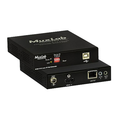
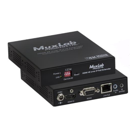
© MuxLab Inc. 2022
3c. If required, connect the computer audio-out and mic-in port to the Transmitter audio-in
and mic-out port, respectively.
3d. If the application is point-to-point, then connect one (1) length of Cat 5e/6 (or higher)
grade UTP cable to the RJ45 LINK connector on the Transmitter. If transmitting over
the network, use an Ethernet Switch between Transmitter and Receiver.
4. To install the Receiver:
4a. Connect the Receiver HDMI port to the Monitor HDMI port with a HDMI compliant
cable.
4b. Connect the two Receiver USB 1.1 ports to a USB keyboard and mouse.
4c. Connect the two Receiver USB 2.0 ports to other USB devices, such as a printer,
drawing pad, storage device, camera, etc.
4d. If required, connect the Receiver audio-out and mic-in port to an amplified speaker and
to a mic system (or headset with mic) respectively.
4e. If the application is point-to-point, then connect one (1) Cat 5e/6 cable (or higher)
coming from the Transmitter, to the RJ45 LINK connector on the Receiver. If
transmitting over the network, use an Ethernet Switch between Transmitter and
Receiver.
5. If the configuration is a multiple point-to-point (including point-to-multipoint) architecture:
5a. You will need to use an Ethernet Switch with Gigabit ports and DHCP Server support.
In addition Jumbo Frame support is required. Verify that the Ethernet Switch is
configured correctly and that the DHCP Server is enabled and that Jumbo Frame
is enabled. See the operating manual for more information about configuring the
Ethernet Switch.
5b. Connect all Transmitters and Receivers to the Ethernet Switch.
5c. Use the DIP Switches to select a unique Device ID for each Transmitter present on the
network and configure each Receiver Device ID to the corresponding selected
Transmitter.
Note: This step is not necessary if the MuxLab Pro Digital Network Controller
(500812) is used.
6. The Transmitter and Receiver supports a directional IR port and RS232 port that can be
utilized if required to transport control signals to control end devices.
7. Powering the Transmitter or Receiver via an external power supply is only necessary where
PoE (PSE) is unavailable. If PoE is unavailable, connect a 5 VDC power supply (500993 -
sold separately) to each Receiver and to an AC power outlet. Next connect each Transmitter
in the same manner. If power is present, the green power LED on each Transmitter and
Receiver will illuminate.
Note: Power ‘ON’ the KVM HDMI over IP PoE Extender, 4K@60 only after all
connections have been made.
8. Power ‘ON’ the HDMI equipment and verify the image quality, sound if applicable, keyboard
and mouse functionality, as well as any additional USB connected devices.
9. Please download and reference the 500800 Operation Manual found on the MuxLab website
(under the 500800 webpage) for further instructions on how to operate this device
10. The following diagram illustrates a typical KVM LAN configuration.
Troubleshooting
The following table describes some of the symptoms, probable causes and possible solutions in regard to
the installation of the KVM HDMI over IP PoE Extender, 4K@60:
