manuals.online logo
Brands
  1. Home
  2. •
  3. Brands
  4. •
  5. Nabco
  6. •
  7. Door Opening System
  8. •
  9. Nabco 243681-05 User manual

Nabco 243681-05 User manual

Page 1 Part # 254915 Effective 10-1-03
NABCO Entrances, Inc.
1-877-622-2694
Muskego, Wisconsin
Installation Instructions
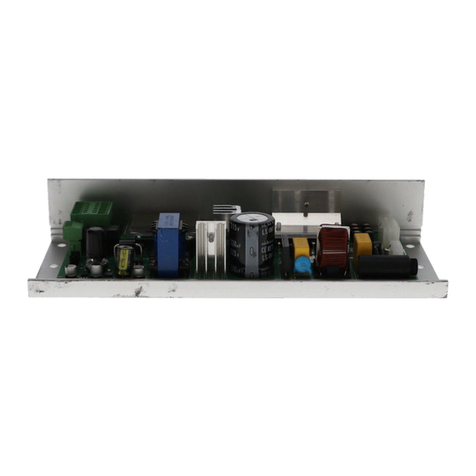
Radio Controls For Automated Door Systems
NABCO Part #243681-05 (4 wire) Receiver 300 MHZ
This combination of radio controls is designed to remotely control
either a NABCO Entrances or a competitor’s automatic door. We
have provided an assortment of wiring diagrams that will allow
installation of the Receiver into many of NABCO’s swing and
sliding automatic door systems. If you need additional information
for competitors products, please contact the NABCO Engineering
Department.
The transmitter/receiver combination is functional with as many as
1024 code variations to accommodate the owner’s preferences. All
radio controls are set with the even numbered switches in the “ON”
p
osition when they leave the factory, therefore, it is recommended
that an alternate code be selected and set at the time of installation.
Please refer to the “Setting the Codes” section for instructions.
The radio frequency (RF) portions of the controls are tuned to
standard frequencies and are thoroughly tested at the factory. No
RF adjustments are needed nor should any be attempted.
TRANSMITTER BATTERY PLACEMENT
Batteries are included in the transmitter. A standard 9 volt battery
is provided. We recommend a high performance battery for longer
life.
Install the battery in the rear of the transmitter. Use a small
screwdriver to pry the code switch access cover from the unit. In
severe cold, warm the transmitter to room temperature before
p
rying on the cover to avoid cracking the plastic tabs.
SETTING THE ACCESS CODES
RECEIVER: Use a small screwdriver to pry the code switch access
cover from the receiver. Use a small screwdriver to set the code
switches on the receiver.
TRANSMITTER: Use a small screwdriver to pry the code switch
access cover from the receiver. Use a small screwdriver to set the
code switches on the receiver so that they match the exact codes on
the receiver. Avoid using sequential or odd/even code sequences.
I
MPORTANT! The code on the transmitter must match the receiver
code exactly or the system will not function. (See Figure #1)
N
ote:
The switches are in the “ON” position when the switch is depressed
toward the number.
After the codes have been set, reinsert the access covers on both
units.
RECEIVER INSTALLATION
The receiver may be mounted directly inside the door header or may
be mounted outside and wired into the door header. The antenna
should be secured outside and extended as far as possible in a
vertical position.
ELECTRICAL CONNECTIONS
POWER REQUIREMENTS
Model 300, 400, 500 &710 swing doors with Magnum or analog
controls do not need a separate power source. The swing door
control board will provide adequate amperage to power the
receiver.
Refer to the wiring diagrams at the back of this manual for more
information.
Model 1175 Sliding Door Systems & Model 300, 400 swing
doors with “U” series microprocessors require a 24 VAC
transformer as a power source. This transformer is NOT provided
in this package and needs to be ordered separately (P/N 142101).
12345678910
Figure 1
Page 2 Part # 254915 Effective 10-1-03
OPERATIONAL CHECK
To verify operation, position yourself at a distance of 25 feet from the receiver and press the transmitter button. Operation should be reliable
at this distance but environment and location of both the transmitter and receiver may affect the range. Try different locations and positions.
If operation is still unsatisfactory, consider the following for troubleshooting:
1. If the door does not open when the wall switch is pressed, be sure that:
a. The transmitter and receiver are set to the same code.
b. The LED on the transmitter illuminates when the button is pushed. If it does not, it could mean:
1. A dead battery
2. A defective transmitter
c. If the LED barely illuminates or only flashes, it could mean:
1. The pulse extender board is defective
2. The battery is weak.
d. The relay is working, it should be heard clicking on the receiver when the transmitter is activated. If no relay can be heard:
1. The transmitter is not sending a signal or the receiver is not receiving it. Try substituting another transmitter or receiver if
available.
3. If, after performing the above operational checks, the controls still do not function, they should be returned to NABCO Entrances for
repair or replacement.
TO REPLACE OR ADD A NEW TRANSMITTER
A replacement or new transmitter or receiver may be matched to the companion receiver or transmitter. To order, specify the Part Number
as noted on the first page of this manual. Customer Service Representatives can provide the proper replacement unit. The digital code must
be reset to match the existing sequence.
FCC NOTICE
Users of the transmitter with the pulse extender board are authorized under part 15 of the FCC rules to use this device without a license.
However, making any modifications not expressly approved by the manufacturer may void the user’s authority to operate this device.
Page 3 Part # 254915 Effective 10-1-03
Figure 2
Wiring Diagram for Radio Activation
on a GT 300, 400, 500, 600 or 710 Swing Door with Magnum Board
Figure 3
Wiring Diagram for Radio Activation and Electric Strike
on a GT 300, 400, 500, 600 or 710 Swing Door with Magnum Board
White
Green
+ Red
- Black
}
CONNECT TO TERMINAL BLOCK #5 RED 24VAC COMMON
24 Volts AC\DC
CONNECT TO TERMINAL BLOCK # 6 BLACK ACTIVATION
CONNECT TO TERMINAL BLOCK # 1 BROWN 24VAC
Four Wire
Radio Receiver
(part # 24-3681-05)
P/N 142101
Customer
LOCK DELAY OPER. LOCK OPER.DELAY
CCNC NO NC NO
+OUT
TRIG REF TRIG 12 - 24V
LOCK RLY OPER RLY MOM GND EXTD POWER
+ Red
- Black
}
CONNECT TO TERMINAL BLOCK #5 RED 24VAC COMMON
CONNECT TO TERMINAL BLOCK #6 BLACK ACTIVATION
OR BLACK WIRE OF ROCKER SWITCH
SA-1 Door sequencer (P/N 1410062)
Brown
Orange
Magnum Control
Four Wire
Radio Receiver
(part # 24-3681-05)
White
24 Volts AC\DC
Green
Supplied 24
VAC Electric
Strike
120 VAC
24 VAC
Transformer
Page 4 Part # 254915 Effective 10-1-03
Figure 4
Wiring Diagram for Radio Activation
on a Swinging, Sliding, or Folding Door with a “U” series Microprocessor
Figure 5
Wiring Diagram for Radio Activation
on a Swing Door Analog Control
White
Green
+ Red
- Black }24 Volts AC\DC
1234
Brown
Orange
Green
(if used)
Red
or
Black
Red
Green
(if used)
Brown
Orange
or
Black
Cut Main Harness and
Splice in Radio
Receiver as Illustrated
ToMicroprocessorControl
24 Volts AC Transformer
Part # 14-2101
Four Wire
Radio Receiver
(part # 24-3681-05)
White
Green
+ Red
- Black }
24 Volts AC\DC
Red - Common
Black - Activation
Blue - 24 VAC
White -Safety
Switch Harness
Four Wire
Radio Receiver
(part # 24-3681-05)
Model
2200
Time
Delay

Other Nabco Door Opening System manuals

Nabco GT20 8300 User manual

Nabco

Nabco GT20 8300 User manual

Nabco GT20 Owner's manual

Nabco

Nabco GT20 Owner's manual

Nabco 710 User manual

Nabco

Nabco 710 User manual

Nabco C-00139 User manual

Nabco

Nabco C-00139 User manual

Nabco ICU 2400 User manual

Nabco

Nabco ICU 2400 User manual

Nabco GYRO TECH GT-1175 Owner's manual

Nabco

Nabco GYRO TECH GT-1175 Owner's manual

Nabco GT20 User manual

Nabco

Nabco GT20 User manual

Nabco GT20 Owner's manual

Nabco

Nabco GT20 Owner's manual

Nabco Opus Control User manual

Nabco

Nabco Opus Control User manual

Nabco Acusensor 3 User manual

Nabco

Nabco Acusensor 3 User manual

Nabco GYRO TECH GT-1175 User manual

Nabco

Nabco GYRO TECH GT-1175 User manual

Nabco GT-1400 User manual

Nabco

Nabco GT-1400 User manual

Nabco GYRO TECH GT-1175 User manual

Nabco

Nabco GYRO TECH GT-1175 User manual

Nabco GYRO TECH GT-1175 User manual

Nabco

Nabco GYRO TECH GT-1175 User manual

Nabco GT 300 User manual

Nabco

Nabco GT 300 User manual

Nabco GT-710 User manual

Nabco

Nabco GT-710 User manual

Popular Door Opening System manuals by other brands

Brady KEYCK installation instructions

Brady

Brady KEYCK installation instructions

Bohle Juna instruction manual

Bohle

Bohle Juna instruction manual

BSW SECURITY 1451 Mounting instruction

BSW SECURITY

BSW SECURITY 1451 Mounting instruction

DITEC VALOR HH-HS Technical manual

DITEC

DITEC VALOR HH-HS Technical manual

Assa Abloy Corbin Russwin PED4800 Series installation instructions

Assa Abloy

Assa Abloy Corbin Russwin PED4800 Series installation instructions

Assa Abloy Sargent PE8800 Series installation instructions

Assa Abloy

Assa Abloy Sargent PE8800 Series installation instructions

Falcon SC71 Series installation instructions

Falcon

Falcon SC71 Series installation instructions

Assa Abloy G-CO-FMS Mounting instructions

Assa Abloy

Assa Abloy G-CO-FMS Mounting instructions

B&D Controll-A-Door RDO-1V4 installation instructions

B&D

B&D Controll-A-Door RDO-1V4 installation instructions

Dorma BTS 65 manual

Dorma

Dorma BTS 65 manual

BEA IXIO-DT3 user guide

BEA

BEA IXIO-DT3 user guide

Dormakaba TS 97 FL XEA Mounting instructions

Dormakaba

Dormakaba TS 97 FL XEA Mounting instructions

GEZE TS 5000 ISM BG manual

GEZE

GEZE TS 5000 ISM BG manual

Helm MK-L 80 G 159 installation instructions

Helm

Helm MK-L 80 G 159 installation instructions

Assa Abloy Norton 9510 Series installation instructions

Assa Abloy

Assa Abloy Norton 9510 Series installation instructions

DoorHan SHAFT-120 Installation and operating manual

DoorHan

DoorHan SHAFT-120 Installation and operating manual

EVVA EMZY Mounting manual

EVVA

EVVA EMZY Mounting manual

Dorma 8956 SPA SP-6 manual

Dorma

Dorma 8956 SPA SP-6 manual

manuals.online logo
manuals.online logoBrands
  • About & Mission
  • Contact us
  • Privacy Policy
  • Terms and Conditions

Copyright 2025 Manuals.Online. All Rights Reserved.