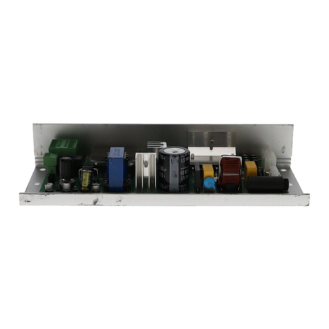
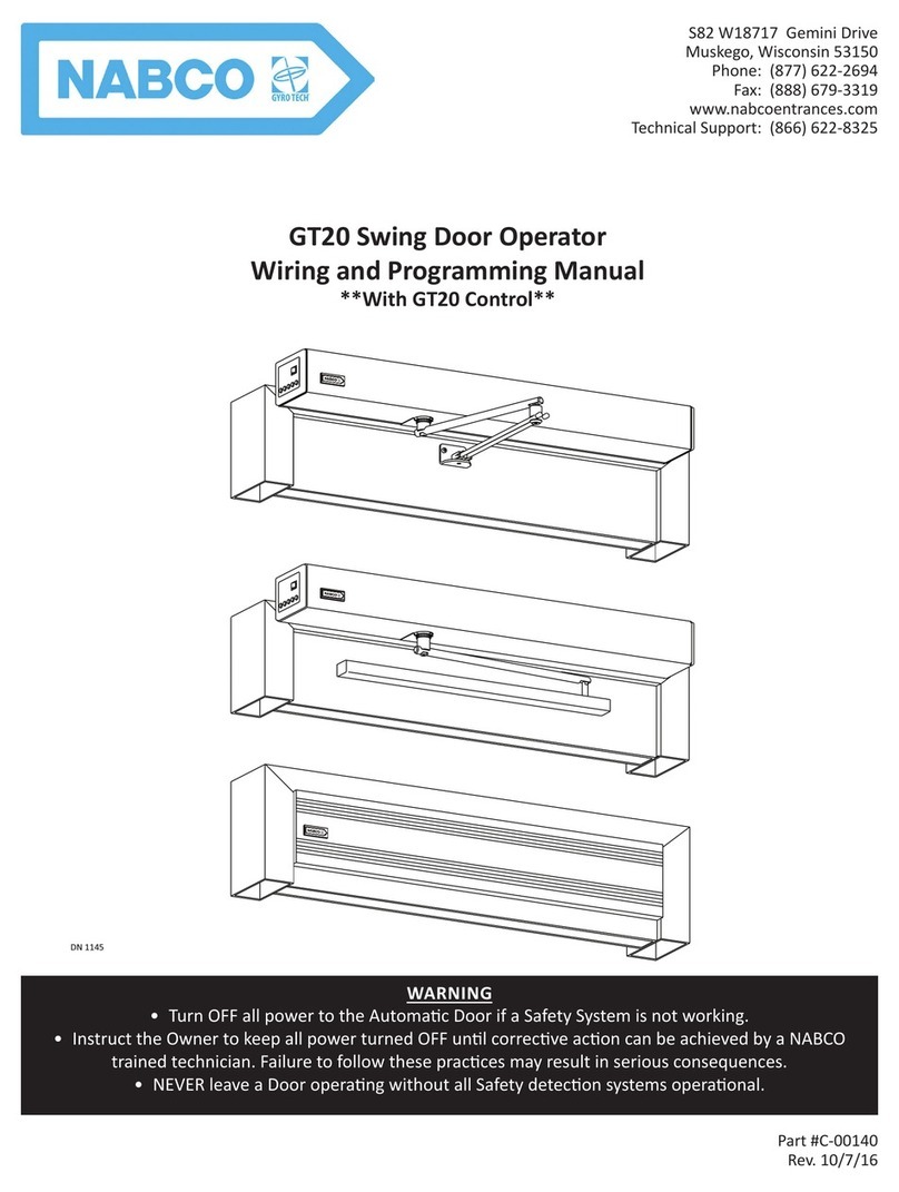
Nabco GT20 Owner's manual

1 of 43
GT20 Wire and Programming Manual
P/N C-00140 Rev 5-7-18
Nabco Entrances Inc. S82 W18717 Gemini Drive Muskego, Wisconsin 53150
Phone: (877) 622-2694 Fax: (888) 679-3319 www.nabcoentrances.com
NABCO hours of Operaon: Monday to Friday 8:00 a.m.- 4:30 p.m. (Central Time)
• Turn OFF all power to the Automatic Door if a Safety System is not working.
• Instruct the Owner to keep all power turned OFF until corrective action can be achieved
by a NABCO trained technician. Failure to follow these practices may result in serious
consequences.
• NEVER leave a Door operating without all Safety detection systems operational.
WARNING
DN 1145

2 of 43
GT20 Wire and Programming Manual www.NabcoEntrances.com
P/N C-00140 Rev 5-7-18
Table of Contents
CHAPTER 1: WARNING LABELS 4
CHAPTER 2: GENERAL SAFETY RECOMMENDATIONS 4
CHAPTER 3: SCOPE 5
CHAPTER 4: 120 VAC GENERAL WIRING 6
CHAPTER 5: THE POWER/PROGRAM SELECTOR 7
SECTION 5.1: Power Switch ........................................................................7
SECTION 5.2: Program Selector Buons ..............................................................7
Table 1 Operang Modes .....................................................................7
CHAPTER 6: PROGRAMMING THE GT20 CONTROL 8
Table 2 Terminals (1-13) ......................................................................8
Table 3 LEDs (14) ............................................................................8
Table 4 Terminal Connecons ..................................................................9
CHAPTER 7: WIRING 10
CHAPTER 8: INITIAL SETUP PROCEDURE 22
SECTION 8.1: The Joysck ........................................................................22
SECTION 8.2: Setup Procedure ....................................................................22
SECTION 8.3: Reset Back to Factory Default ..........................................................25
CHAPTER 9: PROGRAMMING 25
Table 5 The Four Levels of Menu Navigaon ..................................................25
SECTION 9.1: The Home Page .....................................................................26
Table 6 Door Panel Posion ..................................................................26
Table 7 Door Panel Control ...................................................................26
Table 8 Door Panel Operaon .................................................................26
SECTION 9.2: Menu Selecon .....................................................................27
Table 9 Menus .............................................................................27
Table 10 Partameter Menu: Sengs for Door Panel Movement .....................................27
Table 11 Congurator Menu: Sengs for Door Panel Funcons .....................................29
Table 12 Double Door Menu: Simultaneous Pairs and Astragal Pairs .................................30
Table 13 Diagnosc Menu: Diagnosc Tool ......................................................31
Table 14 Error Acve ........................................................................31
Table 15 History Error .......................................................................31
Table 16 REINIT Menu: Reverts Sengs back to Factory Default ....................................32
Table 17 Block/Unblock Menu: Lock Keys .......................................................32
Table 18 Update SoWare ...................................................................32
Table 19 Teach Menu ........................................................................32
CHAPTER 10: DOUBLE SWING DOORS 32

3 of 43
www.NabcoEntrances.com GT20 Wire and Programming Manual
Rev 5-7-18 P/N C-00140
CHAPTER 11: RELAY PRINT 35
SECTION 11.1: Install the Relay PCB Board. ..........................................................35
SECTION 11.2: Program the Relay PCB Board. . . . . . . . . . . . . . . . . . . . . . . . . . . . . . . . . . . . . . . . . . . . . . . . . . . . . . . . .36
CHAPTER 12: TROUBLESHOOTING 37
SECTION 12.1: Malfuncon with Error - No ..........................................................37
Table 20 Drive Mechanism Table ..............................................................38
Table 21 Operang Table .....................................................................39
Table 22 Safety Sensors Table .................................................................39
Table 23 Power Table ........................................................................40
Table 24 Opon ............................................................................40
Table 25 System ............................................................................40
Table 26 Closing Sequence / Interlock Funcon ..................................................40
Table 27 UL Test ............................................................................41
Table 28 Closing Sequence / Interlock Funcon ..................................................41
CHAPTER 14: SOFTWARE UPDATE VIA USB 42
Table 29 LCD display on the Control Unit ........................................................43

4 of 43
GT20 Wire and Programming Manual www.NabcoEntrances.com
P/N C-00140 Rev 5-7-18
CHAPTER 1: WARNING LABELS
Warning labels are universal and used to alert an individual of potential harm to one’s self or to others. The following warning labels
are listed in a hierarchy order that denes the most potential danger rst, and the least potential danger last. Please refer to this page in
the event that a warning label is displayed within this manual and further denition needs to be explained.
Indicates potenally dangerous situaons Danger is used when there is a hazardous situaon
where there is a high probability of severe injury or death It should not be considered for
property damage unless personal injury risk is present
Indicates a hazardous situaon which has some probability of severe injury It should not
be considered for property damage unless personal injury risk is present
Indicates a hazardous situaon which may result in a minor injury Cauon should not be used
when there is a possibility of serious injury Cauon should not be considered for property
damage accidents unless a personal injury risk is present
Aenon: A situaon where material could be damaged or the funcon impaired
Notice: Indicates a statement of company policy as the message relates to the personal safety or protection
of property. Notice should not be used when there is a hazardous situation or personal risk.
Note: Indicates important informaon that provides further instrucon.
CHAPTER 2: GENERAL SAFETY RECOMMENDATIONS
Do not install, operate or service this product unless you have read and understand the General
Safety Recommendaons, Warning Labels, contained in this manual Failure to do so may result
in bodily injury, or property damage
Read, study and understand the installaon and operang instrucons contained in, or
referenced in this manual before operang If you do not understand the instrucon, ask a
qualied technician Failure to do so may result in bodily injury, or property damage and will
nullify all warranes
The GT20 Swing Door Operator Assembly must not be mounted within locaons presenng
explosion hazards The presence of ammable gases or smoke represents a considerable
safety hazard
Disconnect all power to the juncon box prior to making any electrical connecons Failure to
do so may result in seriouc personal or fatal injury When uncertain whether power supply is
disconnected, always verify using a voltmeter
Do not place nger or uninsulated tools inside the electrical controller Touching wires or other
parts inside the enclosure may cause electrical shock, serious injury or death
According UL 325 84, Do Not mount Operator onto ammable surfaces!
The Ground wire from the Opus Control 120 VAC Harness, and the Incoming 120 VAC Ground
wire must be connected to the Ground screw located within the Swing door Header
If the door appears broken or does not seem to work correctly, it should be immediately
removed from service unl repairs can be carried out or a qualied service technician is
contacted for correcve acon
Notice: This manual, the owner’s manual and all other associated manuals must be given to and retained
by the purchasing facility or end user.
Notice: Wiring must meet all local, state, federal or other governing agency codes.
DANGER
WARNING
CAUTION
WARNINGWARNINGWARNING
WARNING
WARNING
DANGER
DANGER
DANGER
CAUTION
CAUTION

5 of 43
www.NabcoEntrances.com GT20 Wire and Programming Manual
Rev 5-7-18 P/N C-00140
Notice: All electrical troublshooting or service must be performed by qualied electrical technicians and
must comply with all applicable governing agency codes.
Note: A Reseable Fuse is located in the Power Supply Module. Do not aempt to repair the U30 Microprocessor Control or the
Power Supply Module other than reseng the fuse.
Aenon: Electrical circuit to Nabco operator must not be not shared with other equipment such as lighng,
cash registers, or any device that might cause electrical interference on the circuit
XThe GT20 swing door drive mechanism may only be installed and operated for indoor use. If this condition cannot be
X
X
in order to continue the operation of the installation.
XIt is the responsibility of the installing door technician to install all warning and instructional labels in accordance
XIt is the responsibility of the purchasing facility or end user to keep warning and instructional labels and literature
assistance.
X
CHAPTER 3: SCOPE
SECTION 31: To the Installer
The purpose of this manual is to familiarize the installer and purchaser with the proper installaon and operaon of this system.
It is essenal that this equipment be properly installed and operaonal before the door is used by the public. It is the installer’s
responsibility to inspect the operaon of the entrance system to be sure it complies with any applicable standards. In the United
States, ANSI Standard 156.10 (Full Power) and ANSI Standard 156.19 (Low Energy) covers the GT20 Swing Door Operator Assembly.
Other local standards or codes may apply. Use them in addion to the ANSI standard. Both Full Power and Low Energy Swing door
Units are listed by UL according to UL325 and is idened as such on the label.
Instruct the building owners and operator on the essenals of the operaon of this device. The owner should follow these
instrucons to determine whether the door is operang properly and should immediately call for service if there is any malfuncon.
All installaon changes and adjustments must be made by qualied, NABCO trained technicians.
Replacement labels and literature may be obtained from local NABCO Entrances, Inc. Distributors. If the name of the local distributor
is unknown, contact NABCO Entrances, Inc. at 1-877-622-2694 for assistance.
The owner should determine that the door is operang properly and should immediately call for service if there is any malfuncon.
All installaon changes and adjustments must be made by qualied, NABCO trained technicians.
SECTION 32: Objecve
The Swing Door Operator assembly is designed to be installed onto the top surface of the Door Frame, or Door Panel. This manual
was created to oer step by step instrucons..
A pedestrian Door that does not have Its glass secons installed at the Factory
shall specify that the glazing material employed is to comply with the requirement in
UL 325 par2951:
“The glazing material in both xed and sliding panels of all sliding doors and in all
unframed swinging doors shall comply with the requirements in the Performance
Specicaons and Methods of Test for Safety Glazing Material Used in Buildings,
ANSI Z971 Glazing material for other pedestrian doors shall also comply with
ANSI Z971, except that single strength or heavier glass may be used for those
porons of doors involving a glazed area of less than 12 (09 m2) and having no
dimension greater than 18 in (457 mm)”
CAUTION

6 of 43
GT20 Wire and Programming Manual www.NabcoEntrances.com
P/N C-00140 Rev 5-7-18
CHAPTER 4: 120 VAC GENERAL WIRING
Shut the installaon site, branch Circuit Breaker OFF Failure to do so may result in serious
personal or fatal injury When uncertain whether power supply is disconnected, always
verify using a voltmeter
All high voltage electrical connecons must be made by licensed electricians according to
Naonal and Local electrical codes/regulaons
Permanent wiring shall be employed as required by local codes
Keep all Incoming 120 VAC wiring separate from low voltage wiring within Header 120 VAC
Power wires must be routed (separate from other wiring) located near the top of inside Header
Ensure that the Grounding of the Electric Power Supply is installed/connected in a proper way
(especially the PE Cable from the Building Side)
All cable used for eld wiring from a Class 2 circuit of an operator to an external device shall be:
a Type CL2, CL2P, CL2R, or CL2X complying with the Standard for Power Limited Circuit Cables,
UL 13, or
b Other cables with equivalent or beer electrical, mechanical, and ammability rangs
Aenon: Depending upon the installaon, the Power Switch/Program Selector may have to be installed
on the opposite side of the Header If 120 VAC Power wires must be installed from Hinge Side of
Header, ensure all wires are securely clipped to prevent pinching of the wires during the Motor/
Operator installaon process
Aenon: Electrical circuit to Nabco operator must not be not shared with other equipment such as lighng,
cash registers, or any device that might cause electrical interference on the circuit
Aenon: Insert all Incoming 120 VAC Power wires into the pre drilled Electric Service Access Hole located at
the le or right side of Header End Cap
Note: It is recommended for the Installer to house all Incoming 120 VAC wires within an Electrical Conduit.
1. Connect the Main Power Supply.
2. Mount the Side Cover.
DN 1177
~2 Cable
L = Live Wire
N = Neutral Wire (Common)
PE = Ground Wire
PE Cable
~1 Cable
Use Copper
Conductors Only
PC-ABS
0548-407
L Cable
N Cable
PE Cable
Figure 1
DANGER
WARNING
CAUTION
CAUTION
CAUTION
CAUTION

7 of 43
www.NabcoEntrances.com GT20 Wire and Programming Manual
Rev 5-7-18 P/N C-00140
CHAPTER 5: THE POWER/PROGRAM SELECTOR
DN 1186
PROGRAM SELECTOR
BUTTONS
POWER SWITCH
GT20 OPERATOR ASSEMBLY
Night
Exit
Automac
HoldOpen
Manual
OPTIONAL
PROGRAM SELECTOR
BUTTONS
Figure 2
Note: Depending upon the installaon, the Power/Program Selector Switch may have to be installed on the opposite side of
the Header.
SECTION 51: Power Switch
The Power Switch is ulized to turn ON/OFF the power supply to the Operator Assembly.
SECTION 52: Program Selector Buons
By pressing the appropriate LED Buon, the Program Selector is ulized to acvate Operang Modes. Each LED Buon is idened by
an Icon.
Table 1
Automac X
X
Night Door Panel can only be opened by an Acvaon Device connected to a Key Terminal (Example: an
exterior card reader).
Open Door Panel will fully open and remain in the Full Open posion.
Manual All acvaon devices are ignored, Door Panel must be opened manually.
An Internal Spring is ulized to:
XClose the Door Panel for Standard Applicaons.
XOpen the Door Panel for Inverse Applicaons (unless the Door Panel has not been locked).
Exit One Way: The Door Panel is opened by an Interior Acvaon Device only.
plus
Completely close the Door Panel (Inverse = open). Hold the Buons MANUAL and EXIT
simultaneously at least 5 seconds. All pending errors will be deleted and a set-up procedure
(Teach) is carried out.
All LED Buons will ash in the event of a pending fatal error.

8 of 43
GT20 Wire and Programming Manual www.NabcoEntrances.com
P/N C-00140 Rev 5-7-18
CHAPTER 6: PROGRAMMING THE GT20 CONTROL
Do not place nger or uninsulated tools inside the electrical GT20 Control Touching wires or
other parts inside the enclosure may cause electrical shock, serious injury or death
Shut Breaker OFF Failure to do so may result in serious personal or fatal injury When
uncertain whether power supply is disconnected, always verify using a voltmeter
DN 1209
②④
⑤
⑥
⑦
⑧
⑨
⑩
⑪
⑭⑮
⑬
⑯
⑱
⑰
②
②
③
①⑫
Table 2
Terminals (1-13)
# Description # Description # Description
1Power/Program Selector Switch 7Reference Switch Connecon 13 Joysck
2Connecon Terminals 8Potenometer (FSlam) 14 LEDs
3LCD Display 9Connecon to Encoder 15 Serial Port
4CAN Bus Port 10 Connecon to Power Supply 16 Status LED = green
5 Processor 11 Buzzer 17 Status LED = green
6Relay PCB Board (available March 2016) 12 USB Port 18 Jumper
Table 3
LEDs (14)
LED Description Indicator
SOK System OK Green ashing
OE acve Opening Element blue = acv
SE acve Safety Element yellow = acv
ERROR ERROR red
E-Lock Relay E-Lock Relay white
DANGER
DANGER

9 of 43
www.NabcoEntrances.com GT20 Wire and Programming Manual
Rev 5-7-18 P/N C-00140
Table 4
Terminal Connections
Terminal Description Connector Description
X101 Opening Command Outside 824 VDC
9OEO
10 GND
X101 Opening Command Inside 11 24 VDC
12 OEI
13 GND
X102 Key Operated Switch 124 VDC
2KEY
3GND
X103 Plug-In connecon to the Power Supply Unit N/A N/A
X104 Emergency Close/Open/Stop 4EmA
5 EmB
X105 Safety Element Stop 14 SE 24V
15 SE Stop
16 SE Test
17 GND
X106 Jumper N/A N/A
X107 Safety Element Reverse 18 SE 24V
19 SE Rev
20 SE Test
21 GND
X108 Motor or Electric Lock 27 EL 24V
28 GND
29 EL-COM
30 EL-NO
31 EL-NC
32 EL-Fb
X110 External Program Selector SA Auto
SL Locked
SO Open
SM Manual
SW One Way
SG GND
X111 Present Sensor PU Programmable I/O Voltage
Sensor is only checked before the door moves PI Programmable Input
PO Programmable Output
PG GND
X113 Connecon to the Encoder N/A N/A
X114 Power/Program Selector Switch N/A N/A
X115 Serial Port N/A N/A
X116 Connecon to the Relay PCB Board
(Available March 2016)
N/A N/A
X117 Can Bus CG GND
CL CAN Low
CH CAN High
X118 USB/Service N/A N/A

10 of 43
GT20 Wire and Programming Manual www.NabcoEntrances.com
P/N C-00140 Rev 5-7-18
CHAPTER 7: WIRING
Shut the installaon site, branch Circuit Breaker OFF Failure to do so may result in serious
personal or fatal injury When uncertain whether power supply is disconnected, always verify
using a voltmeter
All high voltage electrical connecons must be made by licensed electricians according to
Naonal and Local electrical codes/regulaons
Permanent wiring shall be employed as required by local codes
Keep sufcient spacing between high-voltage and low-voltage wiring. 120 VAC Power
wires must be routed (separate from other wiring) located near the top of inside Header
Ensure that incoming electrical ground is properly secured to the grounding screw or
grounding wire, whichever is provided
Aenon: Insert all Incoming 120 VAC Power wires into the pre drilled Electric Service Access Hole located at
the le or right side of Header End Cap
Aenon: Electrical circuit to Nabco operator must not be not shared with other equipment such as lighng,
cash registers, or any device that might cause electrical interference on the circuit
Note: It is recommended for the Installer to house all Incoming 120 VAC wires within an Electrical Conduit.
SECTION 71: Acvaon Devices
DN 1261
Power Ac va on Devices:
Sensors, Card Readers,etc...
All Devices Must Be
N.O. Dry Contact
NONPOWERED ACTIVATION DEVICES
POWERED ACTIVATION DEVICES
Exterior Push Plate
Interior Push Plate
RADIO
RECEIVER
!!!WARNING!!!
Total Power Consump on
of ALL Sensors and Powered
Ac va on Devices
MUST NOT Exceed 1.2 Amps
Exterior
Ac va on
Device
Interior
Ac va on
Device
SA SL SO SM SW
X110 X108
27 28 29 30 31
18 19 20 21
X107
14 15 16 17
X105
10 11 12 13
8 9
X101
X112 X104 X102
X118
X103 X113
R552
X109
U501
S501
X114
X116
30V OK
OE active (Opening element)
System OK
SE active (Safety element)
green
blue
yellow
5V OK
max.m in.
32
green
green
PGPOPIPU CG CHCL
X117
SG
X111
BG BUBD
ERROR
E-Lock Relay
red
white
8
9
10
11
12
13
COM
N.O.
PWR+
PWR-
COM
N.O.
PWR+
PWR-
SA SL SO SM SW
X110 X108
27 28 29 30 31
18 19 20 21
X107
14 15 16 17
X105
10 11 12 13
89
X101
X112
2
X104 X102
X118
X103 X113
R552
X109
U501
S501
X114
X116
30V OK
OE active (Opening element)
System OK
SE active (Safety element)
green
blue
yellow
5V OK
max. min.
32
green
green
PGPOPIPU CG CHCL
X117
SG
X111
BG BUBD
ERROR
E-Lock Relay
red
white
COM
N.O.
10
9
13
12
COM
N.O.
54 31
2
54 31
WARNING
WARNING
CAUTION
CAUTION
CAUTION

11 of 43
www.NabcoEntrances.com GT20 Wire and Programming Manual
Rev 5-7-18 P/N C-00140
SECTION 72: Safety Devices (Oponal)
DN 1262
SA SL SO SM SW
X110 X108
27 28 29 30 31
18 19 20 21
X107
14 15 16 17
X105
10 11 12 13
8 9
X101
X112
54 312
X104 X102
X118
X103 X113
R552
X109
S501
X114
X116
30V OK
OE active (Opening element)
System OK
SE active (Safety element)
gn
bl
ge
5V OK
max. min.
32
gn
gn
PGPOPIPU CG CHCL
X117
SG
X111
BG BUBD
14
15
17
18
19
21
COM
N.C.
PWR+
PWR-
COM
N.C.
PWR+
PWR-
Swing-Side
Door Mounted
Sensor
Approach-Side
Door Mounted
Sensor
WARNING!
When Any Safety Sensor Input is not Used,
A Jumper Must Be In Place At Input Terminals
15 16, and 19 20.
Swing-Side
Overhead
Presence Sensor
COM
N.C.
PWR+
PWR-
WARNING!
Total Power Consumption Of All Sensors And Powered Activation
Devices Must Not Exceed 1.2 Amps.
PG
PO
16
20
PIPU
All Safety Sensors Must Use
Normally Closed Contacts

12 of 43
GT20 Wire and Programming Manual www.NabcoEntrances.com
P/N C-00140 Rev 5-7-18
SECTION 73: Safety with Monitoring Funcon
DN 1605
SA SL SO SM SW
X110 X108
27 28 29 30 31
18 19 20 21
X107
14 15 16 17
X105
10 11 12 13
89
X101
X112
54 312
X104 X102
X118
X103 X113
R552
X109
U501
S501
X114
X116
30V OK
OE active (Opening element)
System OK
SE active (Safety element)
green
blue
yellow
5V OK
max.min.
32
green
green
PGPOPIPU CG CHCL
X117
SG
X111
BG BUBD
ERROR
E-Lock Relay
red
white
14
15
17
19
OUT 1 COM
OUT 1 N.C.
PWR+
PWR-
WARNING!
When Any Door Mounted Sensor Input is not Used,
A Jumper Must Be In Place At Input Terminals
15 16, and 19 20.
Swing-Side
Overhead
Presence Sensor
COM
N.O.
PWR+
PWR-
WARNING!
Total Power Consumption Of All Sensors And Powered Activation
Devices Must Not Exceed 1.2 Amps.
PG
PO
16
21
PIPU
All Safety Sensors Must Use
Normally Closed Contact
s
TEST IN -
TEST IN +
OUT 2 COM
OUT 2 N.C.
OPTEX OA-EDGE
T (with monitoring function) (pink)
(blue)
(white)
(brown)
(violet)
(black)
(green)
(yellow)

13 of 43
www.NabcoEntrances.com GT20 Wire and Programming Manual
Rev 5-7-18 P/N C-00140
SECTION 74: Locking Devices
DN 1263
FAIL SECURE LOCK: POWERED BY THE GT20 CONTROL
• FAIL SAFE and MAG Locks are wired to
Terminal 31 (EL-NC) instead of 30 (EL-NO).
• If the FAIL SECURE Lock has a built-in
FeedBack Switch, connect the Feed-Back
Switch to T
erminals 28 (GND) and 32 (EL-Fb).
• Jumper provided by NABCO is needed
between Terminals 28 (GND) and 29 (EL-COM).
• Power fo
r Lock: 24 VDC (800mA max.)
FAIL SECURE LOCK: POWERED BY OTHER SOURCE
• FAIL SAFE and MAG Locks are wired to
Terminal 31 (EL-NC) instead of 30 (EL-NO).
• If the FAIL SECURE Lock has a built-in
FeedBack Switch, connect the Feed-Back
Switch to T
erminals 28 (GND) and 32 (EL-Fb).
• If present, REMOVE the Jumper between
Terminals 28 (GND) and 29 (EL-COM).
FAIL SECURE
Electric Strike
FAIL SECURE
Electric Strike
Varistor
(MOV, TVS)
Varistor
(MOV, TVS)
Power Supply For
Electric Strike

14 of 43
GT20 Wire and Programming Manual www.NabcoEntrances.com
P/N C-00140 Rev 5-7-18
SECTION 75: Single Swing Door
DN 1296
Header Mounted Presence Sensor
CAN-BUS
External Program Selector
Motor Lock or Electric Lock
Optionally: Feedback signal
Motor Lock or Electric Lock
Softswitch El Fb NO/NC
Safety Element Reversing
Swing Door Mounted Sensor
Opening command inside
Opening command outside
Option Control-Panel
Emerg.-closing/-opening
Emergency Stop
Key-operated switch
Power supply 120, 60Hz
5 amp Service minimum per operator

15 of 43
www.NabcoEntrances.com GT20 Wire and Programming Manual
Rev 5-7-18 P/N C-00140
SECTION 76: Double Swing Door: Master
DN 1267
Header Mounted Presence Sensor
CAN-BUS
External Program Selector
Motor Lock or Electric Lock for Master
Optionally: Feedback signal
Motor Lock or Electric Lock
Softswitch El Fb NO/NC
Safety Element Reversing
Swing Door Mounted Sensor
Opening command inside
Opening command outside
Option Control-Panel
Emerg.-closing/-opening
Emergency Stop
Key-operated Switch
Power supply 120, 60Hz
5 amp Service minimum per operator

16 of 43
GT20 Wire and Programming Manual www.NabcoEntrances.com
P/N C-00140 Rev 5-7-18
SECTION 77: Double Swing Door: Slave
DN 1266
Header Mounted Presence Sensor
CAN-BUS
External Program Selector
Motor Lock or Electric Lock for Master
Optionally: Feedback signal
Motor Lock or Electric Lock
Softswitch El Fb NO/NC
Safety Element Reversing
Swing Door Mounted Sensor
Opening command inside
Opening command outside
Option Control-Panel
Emergency Close
Emergency Stop
Bolt Switching Contact
Key-operated switch
Power supply 120, 60Hz
5 amp Service minimum per operator

17 of 43
www.NabcoEntrances.com GT20 Wire and Programming Manual
Rev 5-7-18 P/N C-00140
SECTION 78: Dual Pair/Simultaneous Pair: Side A
DN 1268
Header Mounted Presence Sensor
CAN-BUS
External Program Selector
Motor Lock or Electric Lock for Master
Optionally: Feedback signal
Motor Lock or Electric Lock
Softswitch El Fb NO/NC
Safety Element Reversing
Swing Door Mounted Sensor
Opening command inside
Opening command outside
Option Control-Panel
Emerg.-closing/-opening
Emergency Stop
Key-operated switch
Power supply 120, 60Hz
5 amp Service minimum per operator

18 of 43
GT20 Wire and Programming Manual www.NabcoEntrances.com
P/N C-00140 Rev 5-7-18
SECTION 79: Dual Pair/Simultaneous Pair: Side B
Header Mounted Presence Sensor
CAN-BUS
External Program Selector
Motor Lock or Electric Lock for Master
Optionally: Feedback signal
Motor Lock or Electric Lock
Softswitch El Fb NO/NC
Safety Element Reversing
Swing Door Mounted Sensor
Opening command inside
Opening command outside
Option Control-Panel
Emerg.-closing/-opening
Emergency Stop
Key-operated switch
Power supply 120, 60Hz
5 amp Service minimum per operator
DN 1269

19 of 43
www.NabcoEntrances.com GT20 Wire and Programming Manual
Rev 5-7-18 P/N C-00140
SECTION 710: Other
DN 1300
SA SL SO SM SW
X110 X108
27 28 29 30 31
18 19 20 21
X107
14 15 16 17
X105
10 11 12 13
89
X101
X112
54 312
X104 X102
X118
X103 X113
R552
X109
U501
S501
X114
X116
30V OK
OE active (Opening element)
System OK
SE active (Safety element)
gn
bl
ge
5V OK
max. min.
32
gn
gn
PGPOPIPU CG CHCL
X117
SG
X111
BG BUBD
WARNING!
To
tal Power Consumption Of
All Sensors And Powered Activation
Devices Must Not Exceed 1.2 Amps.
To Other GT20 Control
(sim-pair, astragal,
sequenced doors)
GND / COMMON
+24VDC
INPUT (key)
Secured Activation Devices (key switch,
number pad, card reader)
Output of Device (N.O. Dry Contact)
connect to terminals 2 & 3.
Power for Device (if needed) provided on
Terminals 1 & 3.
For Security or Fire A
larm Systems
Output of Device (N.C. Dry Contact)
connect to terminals 4 & 5.
When Not Used, Jumper Must Be In Place.
To Optional External
Program Selector
CG-BLACK
CL-WHITE
CH-RED

20 of 43
GT20 Wire and Programming Manual www.NabcoEntrances.com
P/N C-00140 Rev 5-7-18
SECTION 711: Standard Wiring for Single Full-Automac
DN 1523
SA SL SO SM SW
X110 X108
27 28 29 30 31
18 19 20 21
X107
14 15 16 17
X105
10 11 12 13
89
X101
X112
54 312
X104 X102
X118
X103 X113
R552
X109
U501
S501
X114
X116
30V OK
OE active (Opening element)
System OK
SE active (Safety element)
gn
bl
ge
5V OK
max. min.
32
gn
gn
PGPOPIPU CG CHCL
X117
SG
X111
BG BUBD
14
15
17
18
19
21
COM
N.C.
PWR+
PWR-
COM
N.C.
PWR+
PWR-
Swing-Side
Door Mounted
Sensor
Approach-Side
Door Mounted
Sensor
WARNING!
When Any Door Mounted Sensor Input is not Used,
A Jumper Must Be In Place At Input Terminals
15 16, and 19 20.
Overhead
Presence Sensor
(if used)
COM
N.O.
PWR+
PWR-
WARNING!
Total Power Consumption Of All Sensors Must Not Exceed 1.2 Amps.
PG
PO
16
20
PIPU
All Safety Sensors Must Use
Normally Closed Contacts
11
12
13
COM
N.O.
PWR+
PWR-
Activation
Sensor
Other manuals for GT20
2
Table of contents
Other Nabco Door Opening System manuals

Nabco
Nabco GT 300 User manual

Nabco
Nabco 243681-05 User manual

Nabco
Nabco GT20 8300 User manual

Nabco
Nabco GT-710 User manual

Nabco
Nabco GYRO TECH GT-1175 User manual

Nabco
Nabco GYRO TECH GT-1175 User manual

Nabco
Nabco GYRO TECH GT-1175 Owner's manual

Nabco
Nabco C-00139 User manual

Nabco
Nabco Acusensor 3 User manual

Nabco
Nabco 710 User manual