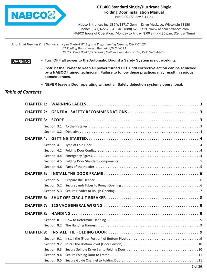
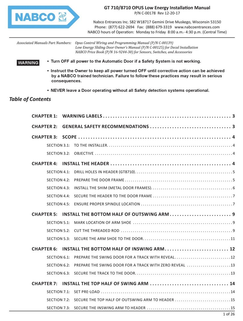
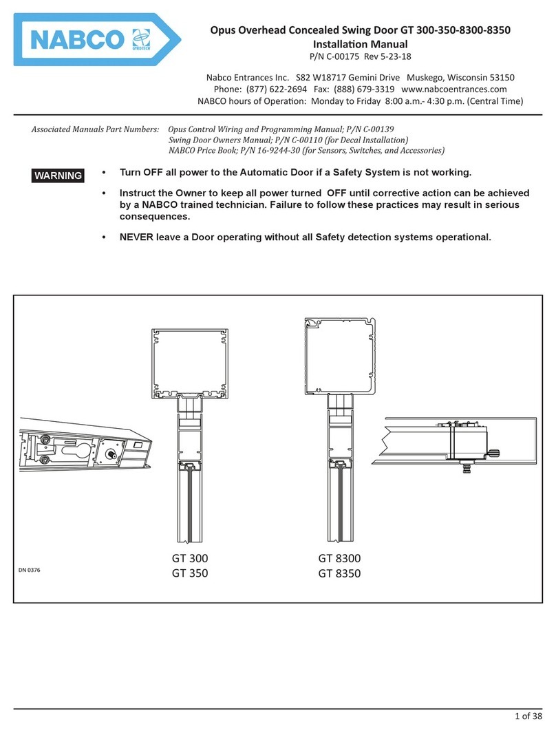
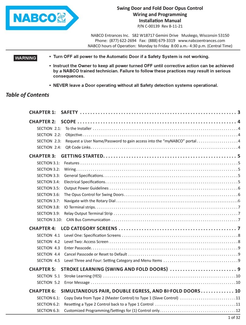
Nabco ICU 2400 User manual

S82 W18717 Gemini Drive
Muskego, Wisconsin 53150
Phone: (877) 622-2694
Fax: (888) 679-3319
www.nabcoentrances.com
Technical Support: (866) 622-8325
NABCO hours of Operaon: Monday to Friday 8:00 a.m.- 4:30 p.m. (Central Time)
P/N C-00394
Rev. 2/28/22
ICU 2400 Automac Sliding Door
OWNER’S MANUAL
A Founding Member of: AAADM
(American Associaon of Automac Door Manufacturers)
WARNING
• Turn OFF all power to the Automac Door if a Safety System is not working.
• Instruct the Owner to keep all power turned OFF unl correcve acon can be achieved by a NABCO
Entrances trained technician. Failure to follow these pracces may result in serious consequences.
• NEVER leave a Door operang without all Safety detecon systems operaonal.
Table of Contents
CHAPTER 1: WARNING LABELS ................................................... 2
CHAPTER 2: GENERAL SAFETY RECOMMENDATIONS ................................ 2
CHAPTER 3: SCOPE.............................................................. 2
SECTION 3.1: To the Customer .................................................................2
SECTION 3.2: Objecve .......................................................................2
CHAPTER 4: GETTING STARTED ................................................... 2
SECTION 4.1: Service Availability ...............................................................3
SECTION 4.2: Safety Standard Compliance .......................................................3
SECTION 4.3: Limited Warranty ................................................................3
SECTION 4.4: Informaon Provided by Door Supplier ..............................................3
CHAPTER 5: GENERAL SAFETY .................................................... 3
CHAPTER 6: OPERATION ......................................................... 4
CHAPTER 7: DAILY SAFETY CHECKS ................................................ 4
Secon 7.1: Presence Sensor ..................................................................4
Secon 7.2: Knowing Act Acvaon .............................................................5
Secon 7.3: Slide Door .......................................................................6
Secon 7.4: Breakout ........................................................................6
CHAPTER 8: SAFETY DECALS. . . . . . . . . . . . . . . . . . . . . . . . . . . . . . . . . . . . . . . . . . . . . . . . . . . . . . 7

ICU 2400 Automac Sliding Door Owners Manual www.NabcoEntrances.com
P/N C-00394 Rev. 2-28-22
2 of 7
CHAPTER 1: WARNING LABELS
Please refer to this section in the event a warning label within this manual needs further explanation.
Indicates a hazardous situaon which has some probability of severe injury. It should not be
considered for property damage unless personal injury risk is present.
Indicates a hazardous situaon which may result in a minor injury. Cauon should not be used
when there is a possibility of serious injury. Cauon should not be considered for property damage
accidents unless a personal injury risk is present.
Noce: Indicates a statement of company policy as the message relates to the personal safety or protecon
of property. Noce should not be used when there is a hazardous situaon or personal risk.
Aenon: A situaon where material could be damaged or the funcon repaired.
Note: Indicates important information that provides further instruction.
CHAPTER 2: GENERAL SAFETY RECOMMENDATIONS
An improperly adjusted door can cause injury and/or equipment damage.
Safety devices must be installed correctly and operaonal.
Do Not operate any Slide Door Unit without fully understanding how a Slide Door funcons. If you
do not fully understand, ask a qualied technician. Failure to do so may result in bodily injury, or
property damage and will nullify all warranes.
Noce: This manual must be given to and retained by the purchasing facility or end user.
Noce: Inspect door operaon daily using the Daily Safety Checklist (within this manual and on door).
Noce: Have door inspected at least annually by an AAADM cered inspector.
CHAPTER 3: SCOPE
SECTION 3.1: To the Customer
The purpose of this manual is to familiarize the Owner with proper operation of the door. It is essential that the Owner
recognizes the importance of maintaining a door system in compliance with industry standards for safety.
It is the responsibility of the Owner/Caretaker to inspect operation of the door on a daily basis. Daily inspection must be done
to ensure safe door operation for use by pedestrians, including (but not limited to) invitees, customers, or employees. This
manual covers ICU 2400 Automatic Slide Doors.
SECTION 3.2: Objecve
This manual provides operation and maintenance requirements, and instructions for a daily safety checklist.
Should the door fail to operate as prescribed in the Daily Safety Check, or at any other me for any
other reason, DO NOT aempt to repair or adjust the door. Call an AAADM Cered technician.
These technicians are trained to service automac door systems in accordance with ANSI/BHMA
A156.38 (Low Energy Power Operated Sliding and Folding Doors).
CHAPTER 4: GETTING STARTED
as a complete package. This package typically includes: an Operator, Controller, Header, Track, Carrier Wheels,
(1) Slide Door, (1) Sidelite, (2) Jamb Tubes, (1) Lock and an Activation/Safety System. Automatic Slide Doors:
XMust include Sensors and Signage for the safety and convenience of the user.
XHave a Safety Zone to cover the area the door travels.
WARNING
CAUTION
WARNING
WARNING
WARNING
WARNING

Rev. 2-28-22 P/N C-00394
www.NabcoEntrances.com ICU 2400 Automac Sliding Door Owners Manual
3 of 7
SECTION 4.1: Service Availability
Door products are distributed through a nationwide network of authorized suppliers for sales, installation, and service.
Immediately contact the Door Manufacturer or the Authorized Door Manufacturer Representative, if service must be
performed on an automatic door system.
SECTION 4.2: Safety Standard Compliance
The automatic door system was designed to comply with the latest operating and safety standards. To ensure continued, safe
operation it is important that:
XThe door system is maintained in compliance with industry standards.
XProper decals/labels are applied and maintained on doors.
X
The American Association of Automatic Door Manufacturers, has established a program to certify automatic door inspectors.
Through this program, inspectors are trained to check door systems for compliance with the appropriate version of an ANSI
standard. In the United States, ANSI Standard 156.38 (Low Energy Power Operated Sliding and Folding Doors) applies.
SECTION 4.3: Limited Warranty
NABCO Entrances Inc. provides to its customer a limited warranty on products. The warranty is:
NABCO ENTRANCES INC. will exchange or repair, F.O.B. the plant, any component found defective
in workmanship and/or material, subject to NABCO’s inspection, for a period of one (1) year
This warranty does not cover loss or damages resulting from causes beyond the manufacturer’s control, misuse, neglect,
accidents, windstorms, or other acts of God, or acts of terrorism. Warranty is for normal use and service. The warranty does
not apply to equipment that has been repaired or altered so as to adversely affect conditions of operation. Warranty will not
obligate NABCO Entrances or damages resulting from such alterations, misuse, or acts of God, or acts of terrorism.
SECTION 4.4: Informaon Provided by Door Supplier
Note: To obtain an AAADM Daily Safety Check video, please go to http://www.aaadm.com/daily-safety-check/index.html
XInstruction on how to conduct the Daily Safety Check.
XLocation of activation Switches and Sensors with instruction of their use.
XCircuit breaker or main power disconnect location for each door system.
XContact number to call for service, or inquiries about the Door system, and/or to report concerns.
X
X
XWarranty information for each door.
CHAPTER 5: GENERAL SAFETY
Pay attention to the following safety items and perform checks periodically where noted.
XForce:
• Force to prevent the door from closing.
• If the door is equipped, force to Breakout the door.
• Force to open door in the event of a power failure.
XIf equipped, Breakout Mode:
• When the door (or door including a Sidelite) is pushed into Breakout mode, check that the door will not activate.
XStrike Stile:
• With door open, grasp the Strike Stile of door and attempt to move it vertically and horizontally. There should be
very little, if any, looseness between door and glass, and/or connections between door and operator
ICU 2400 Automac Sliding Door Owners Manual www.NabcoEntrances.com
P/N C-00394 Rev. 2-28-22
4 of 7
CHAPTER 6: OPERATION
DN 2513
ROCKER SWITCH
A-00805
KEY SWITCH
A-00552
ON
HOLD OPEN
OFF OFF
AUTO OFF H.O.
Rocker Switch
Switch Description
ON When the switch is in ON position, the Door is operational.
OFF When the switch is in the OFF position, the Door is not operational. The OFF position does not shut off the
main power to the Door unit.
HOLD OPEN XDoor is held Open as long as the Switch remains in the Hold Open position.
XDoors should be held Open in this manner. Do Not prop open the doors with any object.
Key Switch
AUTO When the switch is in AUTO position, the Door is operational.
OFF When the switch is in the OFF position, the Door is not operational. The OFF position does not shut off the
main power to the Door unit.
H.O.
(Hold Open)
XDoor is held Open as long as the Switch remains in the Hold Open position.
XDoors should be held Open in this manner. Do Not prop open the doors with any object.
CHAPTER 7: DAILY SAFETY CHECKS
Secon 7.1: Presence Sensor
The ICU 2400 Automatic Slide Door System utilizes a Presence Sensor that activates the Slide Door with Infrared technology.
Infrared Technology is used to scan backwards to detect pedestrians in the threshold until the Slide door is fully closed.
The NABCO Entrances recommendation is for Presence Sensors to detect both moving and non-moving objects in the path of
the door and signal the Control Unit accordingly. ICU 2400 Automatic Slide Doors are typically installed with (1) Sensor on
each side of the Header. In the event a Slide door is still in
the process of closing, and an object is detected within a minimum of (24) inches from the door, the Inactive Sensor will fully
re-open the door.
7.1.1 Sensor Detecon Zone
At about (12) inches away from the door face, walk parallel towards the center of the door opening.
Ensure the Detection Zone is at least as wide as the door opening.
Fully open the Slide door. Crouch motionless in the Threshold for at least (10) seconds. The door should not contact
the pedestrian.
If Holding Beams are installed, open the Door and block the Beam with your Hand.
The Door should not be able to close.

Rev. 2-28-22 P/N C-00394
www.NabcoEntrances.com ICU 2400 Automac Sliding Door Owners Manual
5 of 7
7.1.2 Types of Sensor Malfuncons
Aenon: Examples shown only illustrate some types of causes for Sensor Malfuncons (not all).
DN 1573 DN 1572
An object placed within the Presence Detection Zone that
may be moving within the detection zone (like due to wind).
Sensor is exposed to: Steam, Exhaust Fume, Insects, Heavy
Rain, Heavy Snow.
DN 1571
Within 197” (5m)
DN 1569
Pool of water located within Presence Detection Zone. Multiple Sensors installed close together, or facing each other.
DN 1570 DN 1568
Refl ec ve S cker
XStrong direct Sunlight
X
X
X
X
The bed of a trolley:
X
X
Secon 7.2: Knowing Act Acvaon
Go to the Slide door. Use a Knowing Act Activation.
Opening speed shall be adjusted to open at a speed of (12) inches per second maximum, from fully closed to
fully open.
Slide door shall remain at the fully open position for not less than (5) seconds before starting the closing cycle.
Closing speed shall be adjusted to close at a speed of (6) inches per second maximum per Door Panel, from fully open
to Latch Check.
Latch Check speed shall occur no less than (2) inches from the closed position.

ICU 2400 Automac Sliding Door Owners Manual www.NabcoEntrances.com
P/N C-00394 Rev. 2-28-22
6 of 7
Walk slowly through the door opening. The door should not contact a pedestrian.
Walk out of the Detection Zone.
After a brief time delay (at least 5 seconds), the door should fully close without impact.
Go to the Interior side of Door. Repeat steps.
DN 1729
Figure 1 Walk through Detection Zone
Secon 7.3: Slide Door
If the Slide Door will not be used for at least (1) month, it is recommended to turn Power OFF to
the Unit.
As a prevenve measure, any components showing signs of wear must be replaced by a qualied,
NABCO Entrances trained technician, or service provider. In order to guarantee reliability of the
installaon, any components showing signs of wear must be replaced as a prevenve measure.
Aenon: In the event any type of object needs to be removed from the Sensor Detecon Zone (vicinity), the
Sensor will keep the door open unl it “relearns” the zone before resuming normal operaon. This
may take a minute or two.
activating zones. The purpose of a Daily Safety Check is to ensure pedestrian safety and Owner protection.
Ensure the Power Breaker is switched ON.
Do not switch Power Breaker ON and OFF too quickly.
Ensure the Rocker Switch or Key Switch is set to “ON”.
Check the motion of the Slide door. Slide door should slide freely.
Ensure Full Open Sidelite doors are fully closed.
Failure to do so, will disrupt proper door operation.
Inspect door’s overall condition.
The appropriate signage should be present and hardware should be in good condition.
Ensure the Header Cover, and all other hardware are properly secured.
Check for damaged or missing Weathering.
Ensure Door Latches operate smoothly.
Check all glass for cracks or damage.
Secon 7.4: Breakout
● During Breakout, keep ngers clear of pinch points between the Slide doors.
● Damage can be caused if the Slide Door is not fully open before breakout.
Fully Open the Slide Door.
Breakout cannot occur unless the Slide Door is fully open.
From the side of the Slide Door, Breakout both doors.
In Break Out mode, the door must not activate.
CAUTION
CAUTIONCAUTION
CAUTION

Rev. 2-28-22 P/N C-00394
www.NabcoEntrances.com ICU 2400 Automac Sliding Door Owners Manual
7 of 7
Fully Close both Doors.
Call your supplier if detailed information is needed.
DN 2089
FO Sidelite Panel
Slide Door
Example Shown: Right Hand Unit
Ulity Breakout Side of Door
Figure 2 ICU 2400A Breakout
CHAPTER 8: SAFETY DECALS
Doors shall be equipped with signage visible from either side of the door, instructing the user as to the operation and function
Description
Caution Stand Clear
Automatic Sliding Door
is visible from both sides of the door. Same is true for
the Trail door.
Activate Switch to Operate X(2) Activate Switch signs, shall be adhered to both
sides of door, with the words “Automatic Caution
Door and Activate Switch to Operate” to be
clearly visible.
AAADM
Safety Information Label
Table of contents
Other Nabco Door Opening System manuals

Nabco
Nabco GT20 8300 User manual

Nabco
Nabco GT20 Owner's manual

Nabco
Nabco GYRO TECH GT-1175 User manual

Nabco
Nabco GT-1400 User manual

Nabco
Nabco GT 300 User manual

Nabco
Nabco 710 User manual

Nabco
Nabco GT-710 User manual

Nabco
Nabco Acusensor 3 User manual

Nabco
Nabco GT20 Owner's manual

Nabco
Nabco GT20 User manual
Popular Door Opening System manuals by other brands

ENFORCER
ENFORCER Enforcer E-942FC-600SQ installation manual

Dorma
Dorma BEYOND Mounting instruction

Bohle
Bohle SmartStop GLASS installation instructions

Najm Alfarqadain
Najm Alfarqadain M-238 operation instruction

GEZE
GEZE TS1200 installation instructions

Assa Abloy
Assa Abloy Norton 7970DPS-B Series installation instructions