16. DISPOSAL OF THE SPINDLE
When disposal of a Spindle is necessary, follow the instructions from your local government agency for proper
disposal of industrial components.
9. CHANGING THE TOOL
WARNING
Do not open and close the collet while the brushless motor is running.
CAUTION
・
When the air is supplied to the inlet joint of the Spindle, the tool will be pushed out by
exhausting the coolant air of brushless motor from the edge of Spindle. Be careful not to be
damaged to the tool or be injured.
・Use the air on-off valve through which the air can be exhausted. Do not use 2 way valve,
because the 2 way valve is not echausted and the collet is not closed.
・Do not open and close the collet before the tool is not installed. Because this will cause damage
to the collet or loss of precision.
RECOMMENDATION
Please set the cutting tools to minimize the overhang amount. 13mm is the maximum amount of
overhang to maintain high accuracy and safety.
①Stop the motor. (Or check if the motor is stopped)
②Supply air pressure : from 0.55 - 0.6MPa (79.8 - 87psi) to Air Inlet Joint through 3-way valve. Then, the collet
will be opened. At the same time, the tool is pushed out by the air exhaust for the coolant of motor. So, need
the tool holder not to be damaged to the tool.
③Replace the tool.
④Exhaust the air through 3-way valve. The collet will be closed and the tool can be fixed.
10. REPLACING THE COLLET
CAUTION
Collet will be worn and torn if it will be opened and colsed about 5,000
-
10,000 times. Replace it
with the new collet at this time.
①Stop the coolant air of motor.
②Supply air pressure : from 0.55 - 0.6MPa (79.8 - 87psi) to Air Inlet Joint to keep the collet opened.
Do not take off the tool when the air pressure is supplied
③Place the provided wrench 14mm on the wrench hook of the spindle shaft, and tighten the Spindle.
④Place the provided wrench 9mm on the collet and turn it counterclockwise to loosen the collet. And take off the
collet with the tool from the spindle shaft.
⑤Remove the tool from another collet.
⑥Insert the tool into another collet and turn it clockwise
to be attached on the spindle shaft.
⑦Tight it lightly with the provided wrench 14mm and
wrench 9mm (Specified tightening torque : 1.0 N・m).
⑧Exhaust the air through 3-way valve.
⑨After the collet is replaced, supply the coolant air of
motor to the motor.
11
14
9
12
Tighten
Loosen
Tool
Collet
Spindie Shaft
Fig. 5
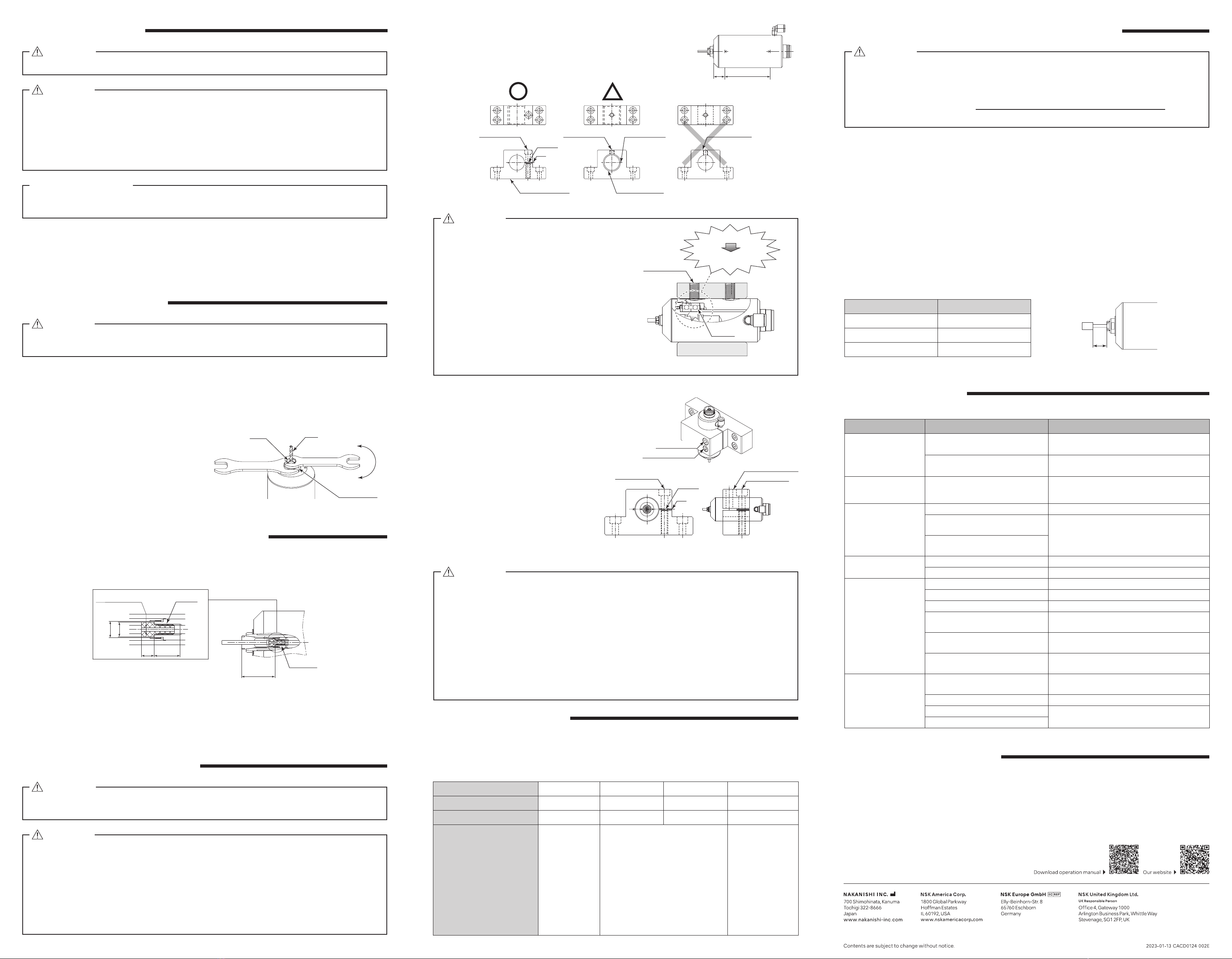
12. INSTALLATION OF THE SPINDLE
11. ADJUSTMENT OF " TOOL MOUNTING DEPTH "
WARNING
When installing a Spindle to a fixed base, make sure the fixed base is grounded in order to avoid
the risk of an electric shock.
CAUTION
・When installing a Spindle, do not hit, drop or cause shock to the Spindle. This may cause
damage to internal components and result in malfunctions.
・When mounting the Spindle, be sure to secure within Clamping Area etched on the Spindle O.D.
If the Spindle is installed incorrectly, damage to the internal components is possible.
・Cautions when tightening the securing bolts on to a Split Type Holder.
Do not over-tighten the bolt. This will cause damage to Spindle's precision.
Tighten the bolt until the Spindle body can not be rotated by hand within the fixture.
Extreme tightening is not necessary or recommended.
Apply working force and check that the Spindle is tight before using.
①When mounting a Spindle, refer to the Clamping Area etched on the
Spindle (Fig. 7).
②When installing a Spindle to the holder, recommended installation
method is shown Fig. 8. Refer to " ③How to fabricate the Split Type
Holder ". If this is not possible, install as shown in Fig. 9.
17
CLAMPING AREA
(Clamping Area)
70
Fig. 7
Bushing with Slit
Fastening Bolt Fastening Bolt
Slit of Bushing
Split Type Holder
Slit
Spacer
Fastening Bolt
Fig. 8 Fig. 10Fig. 9
CAUTION
Do not allow set screws to come directly in
contact with the Spindle body as shown in
Fig. 10, as this will result in damage to the
Spindle housing and internal components.
When installing, never clamp directly over the
bearings, as this will result in bearing damage.
(Refer to Fig. 11)
Bearing
Damage of internal
Components
Deformation
Fastening Bolt
Fig. 11
③How to fabricate the Split Type Holder.
(1) Rough bore the inside diameter of the Split
Type Holder.
(2) Cut a slit. (Ex. Slit 2mm) wide.
(3) Tighten the Screw for Removal and Force
Open the Slit Area.
(4) Insert a spacer (Ex. thickness = 2mm) into
the Slit Area.
(5) Loosen the Screw for Removal, and tighten
the fastening bolt with its specified torque.
(6) Finish the Split Type Holder so that the
inside diameter of the Split Type Holder is
φ
50 with its tolerance range from
-
0.01mm
to
-
0.015mm, and its roundness and
cylindricity of less than 5µm.
(7) When inserting the Spindle loosen the
Fastening Bolt, and tighten the Screw for
Removal, widening the Slit Area.
Fastening Bolt
Spacer
Screw for Removal
Fastening Bolt
Fastening Bolt
Screw for Removal
Side View
Front View
Slit
Fig. 12
CAUTION
・How to confirm the correct tightening or clamping of the Spindles in the holder :
Measure the current value of the CONTROLLER's power cord by the clamp meter.
Fasten the holder so that the increase in the no-load current value (during rotation at the
maximum rotation speed) with the Spindle fastened is 10mA (for type 200V / 230V) or less,
compared to the no-load current value (during rotation at the maximum rotation speed)
without fastening the Spindle. Do not over-tighten the Fastening Bolt. It may damage Spindle's
precision and shorten the life of the bearings.
・The final responsibility for ensuring holder's safety for use in a given application is left to
the designer of the equipment in which NAKANISHI's Spindle is installed. NAKANISHI offers
Spindles with a wide variety of capabilities and specifications.
Please carefully check the Spindle's specifications against the requirements of your equipment
and verify suitability and safety of the Holder prior to initial use.
13. BREAK-IN PROCEDURE
Steps 1 2 3 4
Rotation Speed (min-1) (rpm) 15,000 30,000 40,000 50,000
Rotation Time (min) 15 10 10 15
Items to Check
No Abnormal
Noises
The Spindle housing temperature
during the break-in process should not
exceed 20 degrees C (36 degrees F)
above ambient temperature. Should
the Spindle exceed this limit, rest the
Spindle for at least 20 minutes and re-
start the break in procedure from the
beginning. If the housing temperature
rises again and exceeds 20 degrees
C (36 degrees F) above ambient
temperature, check the Spindle and
motor for proper installation.
The Spindle housing
temperature during
the break
-
in
process should not
exceed 20 degrees
C (36 degrees F)
above ambient
temperature.
Table. 2
During transportation, storage or installation, the grease inside the bearings will settle. If the Spindle is suddenly
run at high-speed, the grease will be ejected from the bearings, causing excessive heat that will cause bearing
damage. After installation, repair, initial operation, or long periods of non operation, please follow the break-in
procedure detailed in Table. 2.
14. CAUTIONS WHEN USING GRINDSTONES AND TOOLS
CAUTION
3.14 x Diameter (mm) x Rotation Speed (min-1) (rpm)
1,000 x 60
Surface Speed (m / s) =
The maximum surface speed or rpm is always specified for a grindstone. Do not exceed the
maximum speed with reference to the calculating chart below. Always follow the grindstone
manufacturer's recommendations.
①The proper surface speed for general grindstones is 10 - 30m/s.
②Do not exceed 13mm of overhang for mounted grindstones as shown in Fig. 13. If the overhang must
exceed 13mm, reduce the motor speed in accordance with Table. 3.
③Dress the grindstone prior to use.
④Do not use cutting tools with bent or broken shanks, cracks or excessive run-out.
⑤For grinding, the maximum depth of cut should not exceed 0.01mm radially or axially. Reciprocate the tool
several times after each pass to eliminate tool pressure.
⑥Always operate cutting tools within the allowable recommended speed of the cutting tools. Use of a cutting
tool outside of the allowable speed of the cutting tools could cause damage to the Spindle and injury to the
operator.
⑦Keep the cutting tool shank and collet clean. If contaminants are left in the collet or collet nut, excessive run-
out will cause damage to the cutting tool and or Spindle.
⑧Do not strike or disassemble the Spindle.
⑨Please set the cutting tools to minimize the overhang amount. 13mm is the maximum amount of overhang to
maintain high accuracy and safety.
Table. 3 Overhang and Speed
Overhang (mm) Max. Speed (min-1) (rpm)
20 N x 0.5
25 N x 0.3
50 N x 0.1
N = Max. Operating Speed with 13mm overhang.
13
Fig. 13
15. TROUBLESHOOTING
Trouble Cause Inspection / Corrective Action
Spindle does not rotate
or rotate smoothly.
The Spindle ball bearings have been
damaged.
Replace the ball bearings.
(Return to NAKANISHI dealer service.)
The motor has been damaged. Replace the motor.
(Return to NAKANISHI dealer service.)
Overheating during
rotation.
Cutting debris has contaminated the
ball bearing, and the ball bearings
are damaged.
Replace the ball bearings.
(Return to NAKANISHI dealer service.)
Abnormal vibration or
noise during rotation.
The tool shank is bent. Replace the tool.
Cutting debris has contaminated the
ball bearing.
Replace the ball bearings.
(Return to NAKANISHI dealer service.)
The Spindle ball bearings have been
damaged.
Tool slippage. Collet is not correctly installed. Check and clean the collet. Reinstall the collet .
The collet is worn. Replace the collet.
High run-out. The tool is bent. Change the tool.
Collet is not correctly installed. Secure the collet correctly.
The collet is worn. Replace the collet.
Inside of the Spindle is worn. Replace the spindle shaft.
(Return to NAKANISHI dealer service.)
Contaminants inside the collet or the
Spindle.
Clean the collet and the inside of the taper and
Spindle.
The Spindle ball bearings have been
damaged.
Replace the ball bearings.
(Return to NAKANISHI dealer service.)
Check can not be
opened and closed.
Poor the air hose. Check all threaded joints and re-tighten if
necessary.
The air hose have been damaged. Replace the air hoses.
Low air pressure. Check and adjusting the air circuit.
Error connection of the air circuit.
If a problem or concern occurs, please check the following prior to consulting your dealer.
Refer to Brushless Motor and E3000 CONTROLLER Operation Manuals.
Please make the stopper by your own to adjust " Tool Mounting Depth "
Utilize the screw M4 x 0.7ℓ10 in the spindle in consideration for " Dimension φA " to fit for tool shank diameter and
the required adjust length (L) refer to Fig 6.
Note 1: The depth to the stopper mounting position is a reference dimension. If you need an accurate depth,
check the actual measurement.
Note 2: Make a φ1.5 through hole in the stopper for air purging.
Without a through hole, air cannot be purged when replacing tools, and dust may enter the collet,
resulting in poor runout accuracy.
(26.4)※
φA
φ6.55
L
M4x0.7
10
Stopper
φ1.5 through hole
(For air purge)
Fig. 6
OM-K0537E006_スピンドル NR50-5100 ATC 取説 英_230124.indd 2OM-K0537E006_スピンドル NR50-5100 ATC 取説 英_230124.indd 2 2023/01/24 9:31:592023/01/24 9:31:59


