manuals.online logo
Brands
  1. Home
  2. •
  3. Brands
  4. •
  5. Nakanishi
  6. •
  7. Industrial Equipment
  8. •
  9. Nakanishi PS Series User manual

Nakanishi PS Series User manual

Thank you for purchasing PS Series Spindle.
PS Series spindles are designed for heavy duty drilling, milling and cutting or on space restricted
machines. Please read this Operation Manual carefully before use, in order to ensure proper usage
and care.
1Caution in Handling
2Features
3Dimensions
4Allowable Max. speed
5Replacing cutting tool
6Replacing Collet Chuck
PS series are not hand tool. Use PS Series installing it on a lathe, NC lathe, a specially
engineered machine and/or automated machine etc.
Use protect cover around PS series and wear protect eye glasses while in operation since it runs.
Do not touch on the spindle while it is running.
Tighten the collet chuck firmly not to come off during the operation.
Before start running the spindle, confirm if the collet chuck is tightened firmly.
Please be especially careful not to hit or crash the bearing caps as this will create unbalanced
rotation causing excessive vibration, heat build up and wear.
Clean the collet chuck often because the collet chuck and the spindle may be hurt and create the
cause of run-out if the debris and polishing powder are sticking in the spindle and the collet
chuck.
Do not exceed spindle speed, refer to 4. Allowable Max. Speed.
1
2
3
4
5
6
Spindle body is precision ground stainless steel (SUS-416) making mounting extremely easy.
Spindle has a labyrinth debris protection system built in and for extreme, conditions positive air pressure
protection is available.
Spindle is available in outer diameters from 20
mm
to 60
mm
, high speed type, low speed type, stainless
steel bearing type, high speed steel bearing type and ceramic bearing type.
1
2
3
D1
D1
D2
(L1)L2
L
Thread
Taper
M1
N1
d1
Fig. 1
Table-1
Model D D1D2LL1L2Chuck
Spanner
d1N1M1
Thread
Taper
PS20-70
PS20-120
PS23-80
PS23-130
PSA23-80
PSA23-130
PSA25-90
PSA25-140
PSA30-100
PSA30-160
PSA35-120
PSA35-180
20
23
23
25
30
35
12.9
16.9
12.9
16.9
18
20
24
110.8
160.7
122.3
172.3
129.7
169.7
133.6
183.6
149.6
209.6
175.6
235.6
15.7
31.8
14.7
18.4
19.4
19.4
70
120
80
130
80
130
90
140
100
160
120
180
CHA
CHK
CHA
CHK
85
10 10
12 14
12 14
12 14
12 14
12 14
15 17
5
7
5
7
9
10.5
11
11
11
11
13.5
16
5.5
8
5.5
8
14
14
M2.6 0.45
M3 0.5
M2.6 0.45
M3 0.5
M4 0.7
M5 0.8
1 / 10
1 / 6
1 / 10
1 / 6
1 / 6
1 / 6
Use under the allowable Max. speed.
Table-2
Model
Allowable
Max. speed
PSA25-90N
PSA25-90H
PSA25-90C
PSA25-140N
PSA25-140H
PSA25-140C
PSA30-100N
PSA30-100H
PSA30-100C
PSA30-160N
PSA30-160H
PSA30-160C
PSA35-120N
PSA35-120H
PSA35-120C
PSA35-180N
PSA35-180H
PSA35-180C
Standard speed
High speed
High speed
(Ceramic bearing type)
Standard speed
High speed
High speed
(Ceramic bearing type)
Standard speed
High speed
High speed
(Ceramic bearing type)
Standard speed
High speed
High speed
(Ceramic bearing type)
Standard speed
High speed
High speed
(Ceramic bearing type)
Standard speed
High speed
High speed
(Ceramic bearing type)
20,000
40,000
40,000
20,000
40,000
40,000
18,000
36,000
36,000
18,000
36,000
36,000
15,000
30,000
30,000
15,000
30,000
30,000
SpecificationModel
Allowable
Max. speed
PA20-70N
PS20-70H
PS20-70C
PS20-120N
PS20-120H
PS20-120C
PS23-80N
PS23-80H
PS23-80C
PS23-130N
PS23-130H
PS23-130C
PSA23-80N
PSA23-80H
PSA23-80C
PSA23-130N
PSA23-130H
PSA23-130C
Standard speed
High speed
High speed
(Ceramic bearing type)
Standard speed
High speed
High speed
(Ceramic bearing type)
Standard speed
High speed
High speed
(Ceramic bearing type)
Standard speed
High speed
High speed
(Ceramic bearing type)
Standard speed
High speed
High speed
(Ceramic bearing type)
Standard speed
High speed
High speed
(Ceramic bearing type)
16,000
32,000
32,000
16,000
32,000
32,000
15,000
30,000
30,000
15,000
30,000
30,000
23,000
46,000
46,000
23,000
46,000
46,000
Specification
1
2
3
Place provided spanner wrench on the spindle.
Place other provided spanner wrench on the
collet cap and turn it counter-clockwise to loosen
the collet cap and pull out the tool.
Collet and collet cap are linked together so that
2 full turns may be required to fully open the collet.
Remove old tool and replace with new one.
Turn collet cap spanner wrench clockwise to fit tightly.
Tool
Collet Cap Loosen
Spindle Tighten
Fig. 2
Follow steps & above (Replacing cutting tool),
and remove collet cap assembly. (Fig. 3)
Collet and Collet cap are linked together.
Hold collet cap firmly in one hand and pull out the
collet chuck while moving it from left to right to
dislogde the collet chuck. (Fig. 4)
Choose a new collet chuck and insert it into collet
cap disagonally to match the collet groove and collet
cap hook. (Fig. 5)
Insert a tool in collet chuck and mount
it into the spindle, and turn it clockwise.
1 21
2
3
4
Tool
Chuck Nut
Loosen
Spindle
Fig. 3
Fig. 5Fig. 4
Collet Chuck
Lean
Collet Cap Move
Collet Cap Hook Push Down
CHA : Standard collet chuck is 3.0
mm
. Optional chucks vary from 0.8 4.0
mm
in 0.1
mm
steps,
and 2.35(0.093"), 3.175(0.125"), are also available.
CHK : Standard collet chuck is 3.0
mm
. Optional chucks vary from 0.8 6.0
mm
in 0.1
mm
steps,
and 2.35(0.093"), 3.175(0.125") and 6.35(1/4") are also available.
CAUTION :
Do not tighten collet cap too much without mounting a tool. The collet chuck will be crushed
unnecessarily and separate from the collet cap. Then, the collet chuck will be difficult to remove
from the spindle even when the collet cap is loosened.
Rev.AOM-K0230E
PS Series
PS-20, 23, PSA-23, 25, 30, 35
7Installation of spindle
8How to supply air for debris protection
9Guidance for belt installation
10 Break-in procedures
11 Pulley removal procedures
12 Cautions when using grindstone
13 Trouble shooting
When installing spindle on a holder, it is not recommendable to fix the spindle with a fastening bolt directly
as shown in Fig. 6 because the sheath is deformed and creates rotating malfunction, heat generation, etc.
Therefore, the installation as shown in Fig. 7 is recommended. In case it is impossible, install it as shown
in Fig. 8.
Fig. 6 Fig. 7 Fig. 8
Fastening Bolt Fastening Bolt Fastening Bolt Slit of Bush
Slit
Bush with Slit
Use a standard screw driver to remove the screw and screw in
a M5 0.8 thread quick disconnect fitting.
For spindles with 2 sealing screws you can use either location.
Supply clean, dry air between 0.1-0.3 MPa pressure.
(Please use caution as contaminated air will void warranty.)
For high speed operation increase belt tension to prevent slipage. During normal speed operation please
reduce belt tension to increase rear bearing life.
If the motor pulley and spindle pulley are offset high speed rotation will produce excess vibration, causing
heating build up and reduced life expectancy.
Please limit pulley center to center offset to less than 0.2
mm
.
Please follow the belt makers usage guidelines.
CAUTION :
Please cover all rotating parts to prevent injury.
Danger : Do not use beyond the peripheral speed of 2,000m/min. because it is dangerous.
Fig. 9
PS Series spindles are high speed spindles, but the following break-in procedures are necessary.
During shipping and storage grease settling will occur. If the spindle is rotated at high speed quickly.
Uneven grease coverage will cause heat build up and bearing damage.
After initial fixturing please follow the break-in procedures to insure optimal life expectancy.
Please follow the break-in schedule in table 3.
Table-3 Break-in schedule
Step 1 2 3 4
Maximum
allowable speed
Duration
Checkpoint
30%
15 minute
No abnormal noise
60%
10 minute
80%
10 minute
Same as step 2.
100%
15 minute
Spindle outer case
approximately 20˚C.
Spindle case should be
less than 20˚C. If case
temperature exceeds
20˚C, please shut down
for 20 minutes. After 20
minute cool down
period restart from step
1. If overheating
continues please check
spindle fixture.
Remove the pulley set screw, use a pulley removal tool to remove pulley. Please male a plate to insert
between the pulley removal tool jaws and the pulley to aid in removal.
Plate
Fig. 10
1
2
3
Follow the recommended speed by the manufacturers when using drill, end mill, etc. Do not use them
beyond the recommended speed because it becomes the cause of malfunction.
Make sure the tool shank is clean. If foreign materials and any debris are left in the collet chuck, they
will affect T.I.R specifications.
The recommendable peripheral speed of vitrified grindstone is within the range of 600 to 1,800m/min.
Peripheral speed = D= Grindstone Diameter
N= Grindstone rpm.
D N
1,000
4Mount a stemmed grindstone within 13
mm
of over-hanging
mode. When mounting a stemmed grindstone longer than
13
mm
over-hanging mode, use it by slowing down the motor
speed. (Fig. 11, Table-4)
Fig. 11
Table-4
Over-hang(
mm
)
20
25
50
(min–1)
N0.5
N0.3
N0.1
5
6
7
8
9
10
11
Do not use a poor quality and run-out grindstone with cracks and scratches.
Try to use a grindstone after dressing is made.
In case of grinding, the depth of cutting in one cycle is within 0.02
mm
.
The depth of cutting for single phase grinding is 0.01
mm
. After one cycle of grinding, repeat reciprocating
motion few times and start next cycle of grinding.
Follow the recommended speed by the manufacturers when using drill, end mill, etc. Do not use them
beyond the recommended speed because it becomes the cause of malfunction.
Make sure the tool shank is clean. If foreign materials and any debris are left in the collet chuck, they
will affect T.I.R specifications.
Do not give an excessive shock and do not disassemble uselessly.
It is dangerous to run the run-out grindstone with cracks and bent shank in a high speed suddenly because the
grindstone may be broken of explode and shank may be bent or broken. When rotating a new grindstone or
grindstone without dressing is made, run it with a low air pressure and increase the speed gradually after
confirming the safety.
Table-5
Phenomenon Probable Cause Corrective Action
Vibration of bur
Foreign substance sticking in side
chuck or spindle Clean chuck and spindle interior
In correct chuck nut setting Set chuck nut correctly
Bearings worn out Replace bearings at service center
Noise and abnormal
vibration
Foreign substance sticking in
bearings Replace bearings at service center
Bearings worn out
Tools bent Replace with proper tool
In correct installation of belt Adjust or replace
No rotation Bearings broken Replace with new bearings at
service center
’06.11.003 S
13mm
This manual suits for next models

24

Other Nakanishi Industrial Equipment manuals

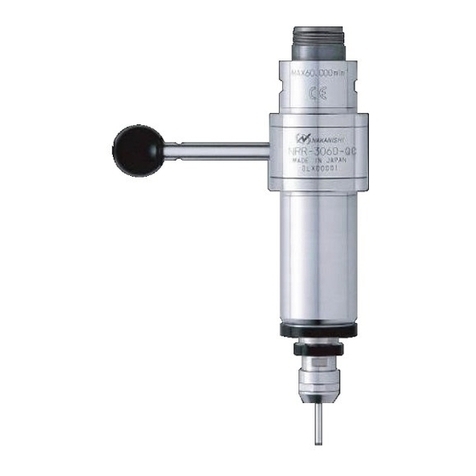
Nakanishi NRR3060-QC User manual

Nakanishi

Nakanishi NRR3060-QC User manual

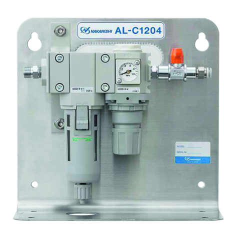
Nakanishi AL-C1204 User manual

Nakanishi

Nakanishi AL-C1204 User manual

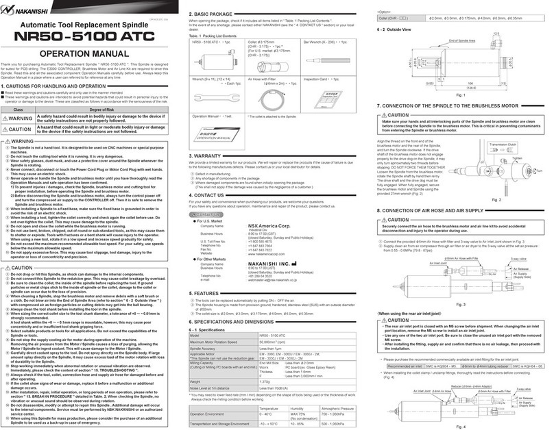
Nakanishi NR50 -5100 ATC User manual

Nakanishi

Nakanishi NR50 -5100 ATC User manual

Nakanishi HES810 User manual

Nakanishi

Nakanishi HES810 User manual

Nakanishi AL-H1207F User manual

Nakanishi

Nakanishi AL-H1207F User manual

Nakanishi NRR4040-QC User manual

Nakanishi

Nakanishi NRR4040-QC User manual

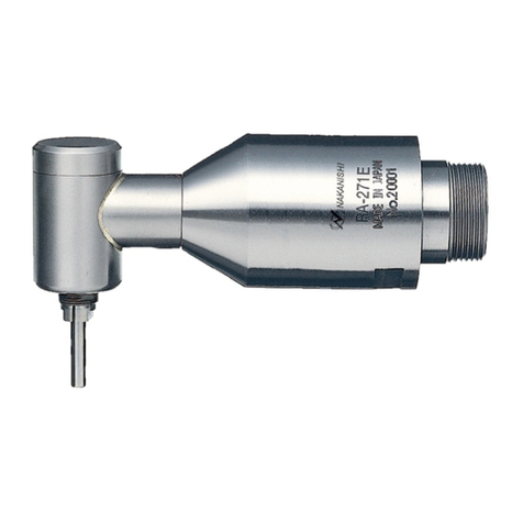
Nakanishi RA-271E User manual

Nakanishi

Nakanishi RA-271E User manual

Nakanishi NR-2551 User manual

Nakanishi

Nakanishi NR-2551 User manual

Nakanishi AL-A1205 User manual

Nakanishi

Nakanishi AL-A1205 User manual

Nakanishi NR3060-AQC User manual

Nakanishi

Nakanishi NR3060-AQC User manual

Nakanishi HTS1501 User manual

Nakanishi

Nakanishi HTS1501 User manual

Nakanishi EMSF-3060K User manual

Nakanishi

Nakanishi EMSF-3060K User manual

Nakanishi NR50 -5100 ATC RS User manual

Nakanishi

Nakanishi NR50 -5100 ATC RS User manual

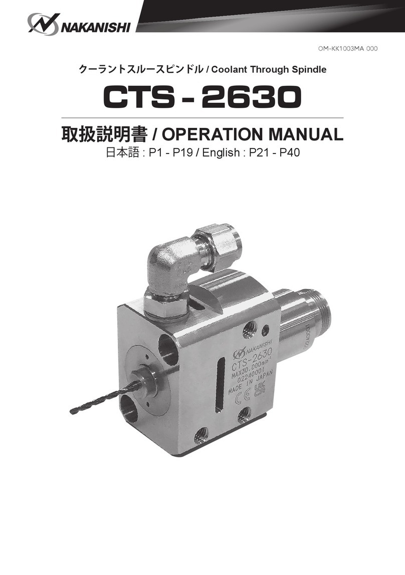
Nakanishi CTS-2630 User manual

Nakanishi

Nakanishi CTS-2630 User manual

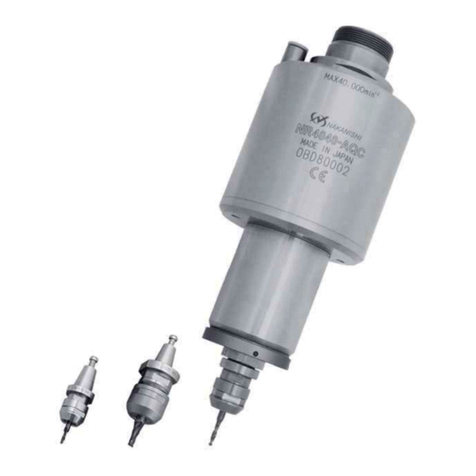
Nakanishi NR4040-AQC User manual

Nakanishi

Nakanishi NR4040-AQC User manual

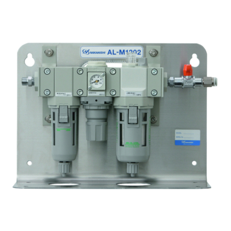
Nakanishi AL-M1202 User manual

Nakanishi

Nakanishi AL-M1202 User manual

Nakanishi RA-100 User manual

Nakanishi

Nakanishi RA-100 User manual

Nakanishi NRR-2651 User manual

Nakanishi

Nakanishi NRR-2651 User manual

Nakanishi EM20-S6000 User manual

Nakanishi

Nakanishi EM20-S6000 User manual

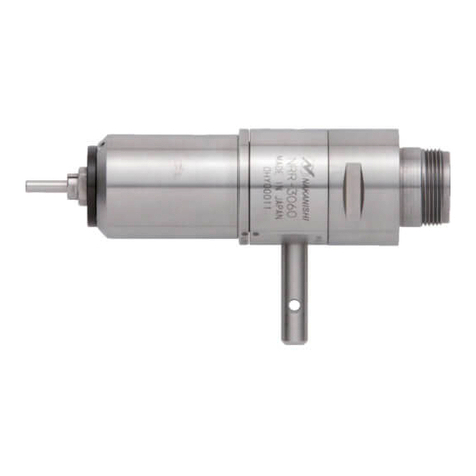
Nakanishi NRR-3060 User manual

Nakanishi

Nakanishi NRR-3060 User manual

Nakanishi RAS-101 User manual

Nakanishi

Nakanishi RAS-101 User manual

Nakanishi AL-M1203BS2 User manual

Nakanishi

Nakanishi AL-M1203BS2 User manual

Nakanishi NR-303 User manual

Nakanishi

Nakanishi NR-303 User manual

Popular Industrial Equipment manuals by other brands

ABB +Q957 user manual

ABB

ABB +Q957 user manual

G.B.C BASIC EDGE 50 instruction manual

G.B.C

G.B.C BASIC EDGE 50 instruction manual

Tronair Batpak 11-6602-1000 Operation & service manual

Tronair

Tronair Batpak 11-6602-1000 Operation & service manual

Pilz PNOZ mi2p Operation manual

Pilz

Pilz PNOZ mi2p Operation manual

Clemco Zero BNP 6012 manual

Clemco

Clemco Zero BNP 6012 manual

Erskine Attachments V-Plow Operator's manual

Erskine Attachments

Erskine Attachments V-Plow Operator's manual

ABB HT610965 Operation manual

ABB

ABB HT610965 Operation manual

Morra MH 540 user manual

Morra

Morra MH 540 user manual

Eaton S090ST manual

Eaton

Eaton S090ST manual

GRIGGIO G 240 P4 instructions

GRIGGIO

GRIGGIO G 240 P4 instructions

Nexen AIR CHAMP HT45 user manual

Nexen

Nexen AIR CHAMP HT45 user manual

WTE V5 installation manual

WTE

WTE V5 installation manual

ABB HT845232 Operation manual

ABB

ABB HT845232 Operation manual

SMC Networks CJP Series Operation manual

SMC Networks

SMC Networks CJP Series Operation manual

JohnDow Industries JDI-AFT58 Operator's manual

JohnDow Industries

JohnDow Industries JDI-AFT58 Operator's manual

IMB MB9016A instruction manual

IMB

IMB MB9016A instruction manual

Clarke CUMB1 Assembly & operating instructions

Clarke

Clarke CUMB1 Assembly & operating instructions

amiad Arkal Spin Klin 2 user guide

amiad

amiad Arkal Spin Klin 2 user guide

manuals.online logo
manuals.online logoBrands
  • About & Mission
  • Contact us
  • Privacy Policy
  • Terms and Conditions

Copyright 2025 Manuals.Online. All Rights Reserved.