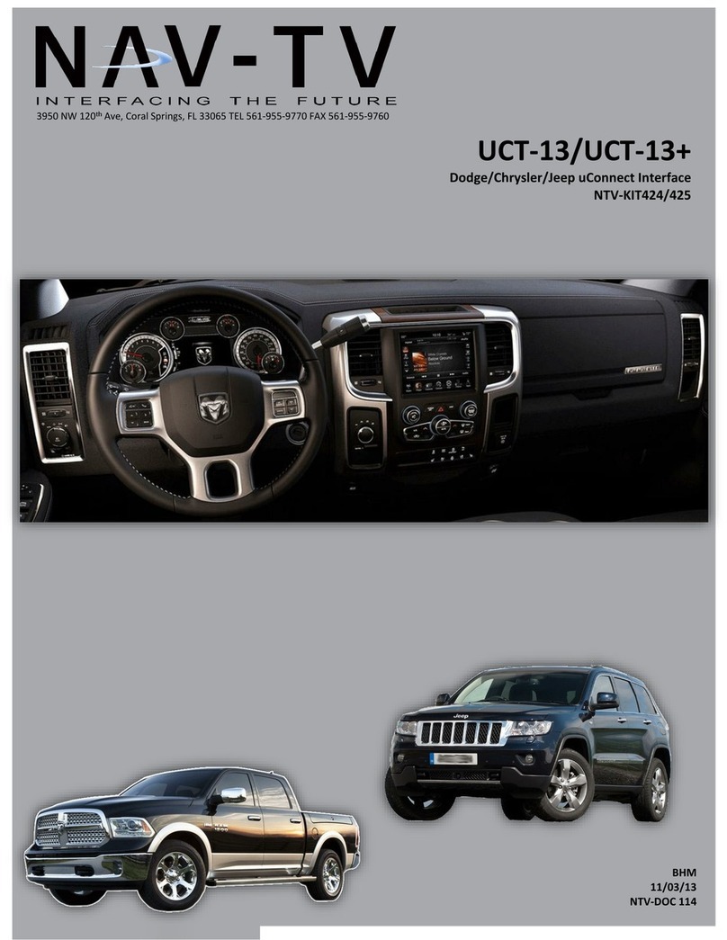
Nav TV UCT-13 User manual

Brendon Martell
February 5, 2013
Nav-TV UCT-13
Dodge UConnect Camera Interface

2 | P a g e
Agreement: End user agrees to use this product in compliance with all State and Federal laws. NAV-TV Corp. would not be held liable for misuse of its product. If you do
not agree, please discontinue use immediately and return product to place of purchase. This product is intended for off-road use and passenger entertainment only.
Included Parts
Needed Tools
Torx t20
Panel tools
Zip ties
7mm driver
Soldering iron, solder
Black tape
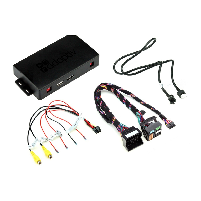
UCT-13 XG Module
XG Harness
USB Cable
AVSW (optional)
Female Video in
RCA
Male Video RCA
(optional)

3 | P a g e
Agreement: End user agrees to use this product in compliance with all State and Federal laws. NAV-TV Corp. would not be held liable for misuse of its product. If you do
not agree, please discontinue use immediately and return product to place of purchase. This product is intended for off-road use and passenger entertainment only.
XG Module connector pinout
Color
Description
PIN #
Connect to PIN
Yellow
Constant Power (12v)
1
RAM 44
RCA MALE
6
RCA Shield
7
White/Brown
CAN HIGH (Radio)
8
RAM 2 (radio side)
White/Blue
CAN HIGH (Vehicle)
9
RAM 2 (vehicle side)
Black
Ground
10
RAM 43
White/Red
ACC Power (12v OUT)
11
White/Blue
Sends (+) out when NAV/AUX is
activated (AVSW V1 Trigger)
12
AVSW 7
White/Purple
Sends (+) out when F. CAM is
activated (AVSW V2 Trigger)
13
AVSW 8
RCA Female (Normally Open)
15
RCA Female (Normally Closed)
16
Brown
CAN LOW (Radio)
17
RAM 12 (Radio side)
Blue
CAN LOW (Vehicle)
18
RAM 12 (Vehicle side)
’13 Dodge Ram Radio connector pinout
Pin #
Description
Color
2
CAN HIGH
Dark Blue
12
CAN LOW
White
31
Diff Video (-)
Green/Brown
32
Diff Video (+)
Green/Orange
33
Shield
43
Ground
Black
44
Constant 12v
Red
Overview
The Dodge UConnect Camera Interface (UCT-13) system allows for multiple video inputs to the factory 8.4” touch
screen in compatible 2013 Dodge Ram 1500 trucks using CAN data filtering. Coupled with our video switcher
(AVSW sold separately), this system will support up to 3 video inputs simultaneously, each activated through the
factory dash controls. This installation requires cutting and soldering, and is not fully plug and play at this time. The
installation for this module is performed behind the factory touch screen.

4 | P a g e
Agreement: End user agrees to use this product in compliance with all State and Federal laws. NAV-TV Corp. would not be held liable for misuse of its product. If you do
not agree, please discontinue use immediately and return product to place of purchase. This product is intended for off-road use and passenger entertainment only.
DO NOT GRAB POWER & GROUND (FOR CAMERA) FROM THE REVERSE LIGHT.
For all installations, the power, ground and CAN wires from the UCT-13 module must be soldered behind the radio screen at
the main connector. Refer to page 3 for diagrams.
If using an AVSW (Nav-TV switcher) and the vehicle has a factory reverse camera, you must cut the DIFF camera signal wires
in half behind the screen, and solder on RCAs from both pair of ends to be plugged into the AVSW (page 6 & 7).
When adding an aftermarket camera: power, ground and signals can be grabbed at the tailgate connector (inside the
tailgate, behind the handle). The wires are as follows:
-Black: Ground
-Pink/Yellow: 12v Ignition
-Green/Brown: Differential Video (-): Connect this wire to the camera’s RCA Signal, at the tailgate only.*
-Green/Orange: Differential Video (+): Connect this wire to the camera’s RCA Shield, at the tailgate only.*
*Note: the above Diff video signal connections appear to be backwards, but they are accurate. Connecting them any other
way will distort the image.
Differential video signal wires (same as those found in the tailgate connector) can be picked up in the drivers kick panel in
the following connector, to expedite install time:
Cut an RCA cable (keep the male end); leave enough length to run from the drivers kick up into the dash behind the radio.
Solder the cut end of the RCA cable to the green/orange (Shield) and green/brown (Signal) wires in the kick panel. Connect
the RCA to the UCT-13’s supplied RCA that you’ve populated behind the radio.
If installing an external AV source, the audio connections must be made at the factory AUX input, in the center console.
Solder ALL connections!
Installation tips

5 | P a g e
Agreement: End user agrees to use this product in compliance with all State and Federal laws. NAV-TV Corp. would not be held liable for misuse of its product. If you do
not agree, please discontinue use immediately and return product to place of purchase. This product is intended for off-road use and passenger entertainment only.
- Female RCA cable for camera input must
be populated in main radio connector.
-Orange lines indicate video RCA
connections.
- AVSW audio ports are
not used.
-Orange lines indicate
RCA video connections.
Figure 1
Figure 2
Install Scenarios

6 | P a g e
Agreement: End user agrees to use this product in compliance with all State and Federal laws. NAV-TV Corp. would not be held liable for misuse of its product. If you do
not agree, please discontinue use immediately and return product to place of purchase. This product is intended for off-road use and passenger entertainment only.
- Garmin NTX54 and Stand
Alone module sold separately.
- AVSW audio ports are not
used.
-Orange lines indicate RCA
video connections.
- XG connection to AVSW is via the RCA
OUTPUT
- Garmin NTX54 and Stand Alone module sold
separately.
- Orange lines indicate RCA video connections.
Figure 3
Figure 4
Install Scenarios

7 | P a g e
Agreement: End user agrees to use this product in compliance with all State and Federal laws. NAV-TV Corp. would not be held liable for misuse of its product. If you do
not agree, please discontinue use immediately and return product to place of purchase. This product is intended for off-road use and passenger entertainment only.
Programming Tips:
Be certain you’re in FM radio mode before attempting to program, otherwise the cluster information
may not display.
The UCT-13 will not program if a door is open. Close all doors before beginning.
If a door is opened while in programming mode, the info screen at the cluster will indicate as such
(overriding Nav-TV programming mode display). The Nav-TV programming mode will return momentarily
if nothing else is touched so that you may continue programming.
Nav-TV programming mode will time out (back to factory) after 15 seconds, however letting the system
timeout will NOT save any changed settings.
In order to save setting changes made in Nav-TV programming mode, you must scroll until you see ‘EXIT’
on the cluster and press enter with the tuning knob, or press the ‘BACK’ button.
Don’t forget to check out YouTube channel ‘NavTV1’ periodically for installation videos!
Programming sequence (cluster)
Selection option
Description
NAVTV Settings
TUNE-Next Item / Enter Change
Rotate TUNE knob to access different menus,
press knob inwards to enter/change setting
RVC
OEM / Retrofit
RVC: Rear view camera. OEM: Factory Dodge
installed camera only. Retrofit: Any
aftermarket camera.
Force RVC
OFF / ON
Enables option of forcing RVC.
F. CAM
OFF / ON
Enables option of installed front camera.
ADD NAV
OFF / ON
Enables option of installed Garmin NAV.
AUX VID
OFF / MANUAL / AUTO
Selects AUX mode setting. Manual: “SCREEN
OFF” button toggles video on & off.
Automatic: Video displays automatically
when sourcing radio to AUX mode.
EXIT
Exits programming mode and saves changes.
Press and hold
(15 seconds) to
enter NAV-TV
settings mode
UCT-13 Programming
While in NAV-TV
settings mode only:
Rotate in clockwise
direction (one detent at
a time!) to scroll
through options. Press
ENTER to change
setting.

8 | P a g e
Agreement: End user agrees to use this product in compliance with all State and Federal laws. NAV-TV Corp. would not be held liable for misuse of its product. If you do
not agree, please discontinue use immediately and return product to place of purchase. This product is intended for off-road use and passenger entertainment only.
UCT-13 Operation
Operation
Shown on cluster
Activate Rear Camera: To force rear camera,
press and hold radio “BACK” button for 2
seconds. To exit forced rear camera, press and
release radio “BACK” button.
Activate Front Camera: To force front camera,
press and hold both radio “SCREEN OFF” &
“BACK” buttons together for 2 seconds. To exit
forced front camera, press and release radio
“BACK” radio.
Activate NAV mode: To activate the NAV
screen, press and hold radio “SCREEN OFF”
button for 2 seconds. To exit NAV mode, press
and release the “BACK” button.
Activate Aux Video: To activate the auxiliary
video mode, the radio must be in the AUX
source mode, which is found in the “MEDIA”
section on the touch screen. If you have “AUX”
programmed to automatic (refer to
programming), the video should appear as soon
as you select “AUX”. If you have “AUX”
programmed to manual, once in “AUX” source
mode, you must press and release “SCREEN
OFF”. To exit AUX Video mode, press and
release the same “SCREEN OFF” button again.
Press for 2 seconds to activate
NAV (optional)
Hold both ‘SCREEN OFF’ and ‘BACK’ together for 2
seconds to force front camera (optional)
Press for 2 seconds to force
rear camera

9 | P a g e
Agreement: End user agrees to use this product in compliance with all State and Federal laws. NAV-TV Corp. would not be held liable for misuse of its product. If you do
not agree, please discontinue use immediately and return product to place of purchase. This product is intended for off-road use and passenger entertainment only.
Dodge Ram Radio removal
4
Remove the Torx 20 screw at the rear of
the pocket on the right side of the dash.
Remove 2 more Torx 20 screws at the
top of the dash. They are hidden
beneath a rubber mat.
The face should be free now, pull
straight outwards (towards you) with
medium force. Use plastic panel tools if
necessary.
Remove (4) 7mm screws that secure the
LCD touchscreen.
1
2
3

10 | P a g e
Agreement: End user agrees to use this product in compliance with all State and Federal laws. NAV-TV Corp. would not be held liable for misuse of its product. If you do
not agree, please discontinue use immediately and return product to place of purchase. This product is intended for off-road use and passenger entertainment only.
Q1. I can’t get into programming mode.
A1. Verify your CAN data wires are connected properly. Make certain you are in FM radio mode before you begin
programming, otherwise the cluster information might not display. Hold down the “MUTE” button until you see the display
options post on the cluster.
Q2. I’m getting no image at all on my factory screen.
A2. Verify your connections are correct, starting with the CAN data wires. Also check that the video RCA supplied is
been populated in the correct location.
Q3. When I try to force (front, rear) camera, nothing happens.
A3. Make certain you’ve enabled the options you want to use in the Nav-TV settings mode. Refer to page 7.
Q4. I hear no audio when my auxiliary source is playing on screen.
A4. You must run audio up into the center console AUX jack to get sound through the speakers in AUX mode.
Q5. I’ve added an aftermarket camera, when the camera image is displayed, video is scrambled.
A5. Swap the video & shield connections going to the radio.
FAQs
Other manuals for UCT-13
1
Table of contents
Other Nav TV Automobile Electronic manuals

Nav TV
Nav TV Tooki Audi User manual

Nav TV
Nav TV MOST-HUR MB User manual

Nav TV
Nav TV REC-AV XG User manual

Nav TV
Nav TV NTV-KIT701 User manual

Nav TV
Nav TV Volvo VIM User manual

Nav TV
Nav TV UCT-13 User manual

Nav TV
Nav TV Genesis VIM XG User manual

Nav TV
Nav TV Sonata-CAM User manual

Nav TV
Nav TV OPI-A User manual

Nav TV
Nav TV NTV-KIT873 User manual
Popular Automobile Electronic manuals by other brands

B&G electronics
B&G electronics PW-100 Installation and operation manual

Audiotechnik Dietz
Audiotechnik Dietz 66103 instruction manual

Directechs
Directechs DB3 installation guide

Perfect Tuning
Perfect Tuning Universal Gauge user manual

Innova
Innova 3130b owner's manual

Saab
Saab 32 025 686 installation instructions