manuals.online logo
Brands
  1. Home
  2. •
  3. Brands
  4. •
  5. Nav TV
  6. •
  7. Automobile Electronic
  8. •
  9. Nav TV UCT-13 User manual

Nav TV UCT-13 User manual

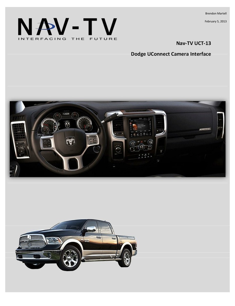
UCT-13/UCT-13+
Dodge/Chrysler/Jeep uConnect Interface
NTV-KIT424/425
BHM
11/03/13
NTV-DOC 114
3950 NW 120th Ave, Coral Springs, FL 33065 TEL 561-955-9770 FAX 561-955-9760
BHM
11/03/13
NTV-DOC 114
Agreement: End user agrees to use this product in compliance with all State and Federal laws. NAV-TV Corp. would not be held liable for
misuse of its product. If you do not agree, please discontinue use immediately and return product to place of purchase. This product is
intended for off-road use and passenger entertainment only.
2 | P a g e
Overview
The Dodge uConnect Camera Interface (UCT-13) system allows for multiple video inputs to the
factory 8.4” touch screen in compatible 2013 Dodge and Jeep vehicles. Coupled with our video
switcher (included in NTV-KIT425), this system will support up to 3 video inputs simultaneously,
each activated through the factory dash controls.
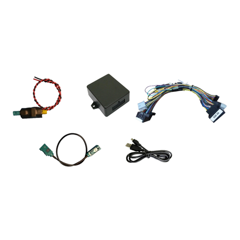
Kit Contents
Plug & Play T-harness
NTV-HAR246
UCT-13 Module
NTV-ASY166
USB Cable (updates)
NTV-CAB009
AVSW
NTV-KIT224
Rear View Cam
Front Cam
AUX Video
Control in Motion
(2x) Audio RCA-3.5mm Adapter
NTV-CAB054
(3x) Male barrel RCA
NTV-CON018
Power Trigger Harness
NTV-HAR066
Included with UCT-13+ kit only (NTV-KIT425)
BHM
11/03/13
NTV-DOC 114
Agreement: End user agrees to use this product in compliance with all State and Federal laws. NAV-TV Corp. would not be held liable for
misuse of its product. If you do not agree, please discontinue use immediately and return product to place of purchase. This product is
intended for off-road use and passenger entertainment only.
3 | P a g e
UCT-13 pin out
2013 Dodge/Jeep Radio LCD connector pin out
PIN #
Description
Color
1
12v (+) Constant
Yellow
6
RCA MALE
--
7
RCA Shield
--
8
CAN HI (Radio Side)
White/Brown
9
CAN HI (Car Side)
White/Blue
10
Ground (-)
Black
11
Provides 12v (+) ACC OUT
White/Red
12
(+) Output when NAV/AUX is act (AVSW
V1 Trigger)
Blue
13
(+) Output when F. CAM is act (AVSW V2
Trigger)
Purple
15
RCA Female (Normally Open)
--
16
RCA Female (Normally Closed)
--
17
CAN LO (Radio Side)
Brown
18
CAN LO (Car Side)
Blue
Pin #
Description
Color
2
CAN HIGH
Dark Blue
12
CAN LOW
White
31
Diff Video (-)
Green/Brown
32
Diff Video (+)
Green/Orange
33
Shield
43
Ground
Black
44
Constant 12v
Red
Wire Side
PIN Side
BHM
11/03/13
NTV-DOC 114
Agreement: End user agrees to use this product in compliance with all State and Federal laws. NAV-TV Corp. would not be held liable for
misuse of its product. If you do not agree, please discontinue use immediately and return product to place of purchase. This product is
intended for off-road use and passenger entertainment only.
4 | P a g e
Dash Disassembly (RAM)
1. Remove the Torx t20 screw at the right rear of the pocket on the
right side of the dash.
2. Remove (2x) Torx t20 at the top of the dash. They are hidden beneath a rubber mat.
3. The face should be free now, pull straight
outwards (towards you) with medium force. Use
plastic panel tools if necessary.
4. Remove (4x) 7mm screws that secure the
LCD touchscreen.
BHM
11/03/13
NTV-DOC 114
Agreement: End user agrees to use this product in compliance with all State and Federal laws. NAV-TV Corp. would not be held liable for
misuse of its product. If you do not agree, please discontinue use immediately and return product to place of purchase. This product is
intended for off-road use and passenger entertainment only.
5 | P a g e
UCT-13 Module Installation
Adding a reverse camera only:
1. After removing the factory radio, gather the Plug & Play T-harness and
connect the female side to the factory 44-pin plug. Make certain the lock
connects together securely.
2. After installing a rear camera, connect the signal RCA to the yellow RCA on the
male side (side going into monitor) of the Plug & Play T-harness. The other side
of the yellow RCA can be left disconnected. *The harness is shipped with the AV
RCA’s disconnected, be sure to plug the audio RCAs together if the AVSW is
not used. If left disconnected, the AUX audio jack will not pass thru.
3. Connect the UCT-13 module to the 18-pin connector found in the Plug &
Play T-harness.
4. Connect the monitor to the male side of the Plug & Play harness. Reconnect all other plugs to
the monitor and skip to Programming on Page 8.
Refer to installation diagrams for visual aid (pages 6-7)
Adding a reverse camera and additional AV inputs (UCT-13+):
1. After removing the factory radio, gather the Plug & Play T-harness and connect the female side
to the factory 44-pin plug. Make certain the lock connects together securely.
2. Gather the AVSW Trigger harness and connect the following 3 wires:
AVSW Trigger harness wire
Connect to
Black (pin 3)
Chassis ground
White/Red (pin 7)
Purple (‘AVSW 2’) wire from UCT13
White/Blue (pin 8)
Blue/White (‘AVSW 1’) wire from UCT13
3. Connect the white connector from the trigger harness to the AVSW at the proper port.
4. Signal for the rear camera will connect to yellow input RCA on the AVSW at the port labeled
‘FACTORY AV (TO VEHICLE)’. If adding only video to the factory screen, leave the black and red
audio RCAs connected (straight pass through) in the Plug & Play harness. Refer to page 6, Fig 2
for a diagram of this.
5. When adding A/V AUX, the male RCAs (vehicle side), plug into the ‘FACTORY AV’ of the AVSW.
The female RCAs (radio side); requires male barrel connectors, plug into the ‘AV out’ of the
AVSW. (IN vs. OUT. See page 7, Fig 3 & 4).
6. AVSW input
references:
7. Connect the UCT-13 module to the 18-pin connector found in the Plug & Play T-harness.
8. Connect the monitor to the male side of the Plug & Play harness. Reconnect all other plugs to
the monitor and skip to Programming on Page 8.
Cluster
AVSW input
RVC (forced rear view cam)
Video pass-thru (FACTORY AV input)
Front Cam
V2
AUX
V1; A1
BHM
11/03/13
NTV-DOC 114
Agreement: End user agrees to use this product in compliance with all State and Federal laws. NAV-TV Corp. would not be held liable for
misuse of its product. If you do not agree, please discontinue use immediately and return product to place of purchase. This product is
intended for off-road use and passenger entertainment only.
6 | P a g e
Fig 1: Rear Camera Only
Installation Diagrams
.
Fig 2: Adding front camera with factory rear camera
BHM
11/03/13
NTV-DOC 114
Agreement: End user agrees to use this product in compliance with all State and Federal laws. NAV-TV Corp. would not be held liable for
misuse of its product. If you do not agree, please discontinue use immediately and return product to place of purchase. This product is
intended for off-road use and passenger entertainment only.
7 | P a g e
*Note: This diagram assumes
the vehicle has a factory
reverse camera. If you are
adding an aftermarket
camera, signal input must
connect to the yellow RCA @
‘FAVTORY AV’ on the AVSW.
*Note: This diagram assumes
the vehicle has a factory
reverse camera. If you are
adding an aftermarket
camera, signal input must
connect to the yellow RCA @
‘FAVTORY AV’ on the AVSW.
Fig 3: Adding AUX
Fig 4: Adding AUX and cameras
BHM
11/03/13
NTV-DOC 114
Agreement: End user agrees to use this product in compliance with all State and Federal laws. NAV-TV Corp. would not be held liable for
misuse of its product. If you do not agree, please discontinue use immediately and return product to place of purchase. This product is
intended for off-road use and passenger entertainment only.
8 | P a g e
UCT-13 Programming
Programming the UCT-13 module is done through the factory dash MUTE button, TUNING KNOB, and
CLUSTER LCD for feedback.
1. Before attempting to program, after making connections, let the vehicle go
to sleep. Do this by closing all doors/trunk/hood, lock the vehicle and
waiting 5 minutes before proceeding to program.
2. Turn the vehicle’s ignition on. Be certain you’re resting in FM mode (see an
FM station frequency on the cluster), otherwise the cluster information
may not display.
3. Close all doors (door status may override Nav-TV settings cluster feedback).
4. View the chart below for settings descriptions and the diagram above to begin programming.
5. Nav-TV programming mode will time out (back to factory) after 15 seconds, however letting the
system timeout will NOT SAVE any changed settings. Scroll to the end of the settings menu and
press ‘EXIT’ to exit and save settings.
Programming sequence (cluster)
Selection option
Description
NAVTV Settings
TUNE-Next Item / Enter
Change
Rotate TUNE knob to access different menus, press knob
inwards to enter/change setting
RVC
OEM / Retrofit
RVC: Rear view camera. OEM: Factory Dodge installed
camera only. Retrofit: Any aftermarket camera.
Force RVC
OFF / ON
Enables option of forcing RVC.
F. CAM
OFF / ON
Enables option of installed front camera.
AUX VID
OFF / ON
Enables option of AUX VIDEO
EXIT
Exits programming mode and saves changes.
Press and HOLD (15
seconds) to enter
NAV-TV settings
mode
While in NAV-TV
settings mode
only:
Rotate clockwise
(one detent/time)
to scroll through
options. Press
ENTER to change
setting.
BHM
11/03/13
NTV-DOC 114
Agreement: End user agrees to use this product in compliance with all State and Federal laws. NAV-TV Corp. would not be held liable for
misuse of its product. If you do not agree, please discontinue use immediately and return product to place of purchase. This product is
intended for off-road use and passenger entertainment only.
9 | P a g e
Operation
Displayed on cluster LCD
UCT-13 Operation
Activate Rear Camera: To force rear camera, press and hold radio ‘BACK’
button for 2 seconds. To exit forced rear camera, press and release radio
‘BACK’button.
Activate Front Camera: To force front camera, press and hold both radio
‘SCREEN OFF’& ‘BACK’ buttons together for 2 seconds. To exit forced front
camera, press and release radio “BACK” radio.
Activate Aux Video mode: To activate the AUX screen, press and hold
radio ‘SCREEN OFF’button for 2 seconds. To exit NAV mode, press and
release the ‘BACK’button.
Activate CIM (Control in Motion): To activate CIM for factory navigation,
press and hold the ‘Volume’ button for 3 seconds (CIM will disable
automatically after 60 seconds). This function will reset upon every key
cycle.
CIM: Hold (3
sec) to
activate
Force front camera: Hold both
‘SCREEN OFF’ & ‘BACK’ (2 sec)
AUX: Press & hold (2
sec) to activate
Force rear camera:
Press & hold (2 sec)
BHM
11/03/13
NTV-DOC 114
Agreement: End user agrees to use this product in compliance with all State and Federal laws. NAV-TV Corp. would not be held liable for
misuse of its product. If you do not agree, please discontinue use immediately and return product to place of purchase. This product is
intended for off-road use and passenger entertainment only.
10 | P a g e
FAQs
Q1. I can’t get into programming mode.
A1. Turn off the vehicle and remove the key. Close all points of entry and use the remote to lock
the vehicle. Wait approx. 5 minutes without opening or disturbing the vehicle. Unlock and cycle the
ignition to the ‘RUN’ position. Make certain that the cluster is in FM radio mode before you begin
programming; and no errors are displayed (door open, etc), otherwise the cluster information might not
display. Hold down the “MUTE” button until you see the display options post on the cluster.
Q2. When I try to force (front, rear) camera, nothing happens.
A2. Make certain you’ve enabled the options you want to use in the Nav-TV settings mode.
Refer to page 8.
Q3. I hear no audio when my auxiliary source is playing on screen.
A3. Verify that the audio RCAs are connected properly to the AVSW.
Q4. Everything works properly, but when an audio source is connected to the 3.5mm audio jack,
there’s no audio.
A4. Make sure the audio RCAs are connected together on the Plug-n-Play harness.
Q5. When I place the vehicle into reverse, I get a black screen.
A5. Make sure the camera is getting sufficient power and the RCA is connected to the YELLOW
RCA behind the screen, NOT to the RCA on the UCT13.
Q6. The camera image is displayed properly when the vehicle is in reverse, but there’s only a black
screen when the camera is forced.
A6. Make sure the camera power is not connected to the reverse lamps. Camera power needs to
be connected to an accessory wire (cigarette lighter).

Other manuals for UCT-13

1

This manual suits for next models

1

Other Nav TV Automobile Electronic manuals

Nav TV SRX VIM User manual

Nav TV

Nav TV SRX VIM User manual

Nav TV TOOKI-POR User manual

Nav TV

Nav TV TOOKI-POR User manual

Nav TV Genesis VIM XG User manual

Nav TV

Nav TV Genesis VIM XG User manual

Nav TV NTV-KIT805 User manual

Nav TV

Nav TV NTV-KIT805 User manual

Nav TV UCT-13 User manual

Nav TV

Nav TV UCT-13 User manual

Nav TV OPV-2LR User manual

Nav TV

Nav TV OPV-2LR User manual

Nav TV MOST-HUR MB User manual

Nav TV

Nav TV MOST-HUR MB User manual

Nav TV NTV-KIT701 User manual

Nav TV

Nav TV NTV-KIT701 User manual

Nav TV REC-AV XG User manual

Nav TV

Nav TV REC-AV XG User manual

Nav TV AUDI DYNAMIC-INT User manual

Nav TV

Nav TV AUDI DYNAMIC-INT User manual

Nav TV OPI-A User manual

Nav TV

Nav TV OPI-A User manual

Nav TV Sonata-CAM User manual

Nav TV

Nav TV Sonata-CAM User manual

Nav TV Volvo VIM User manual

Nav TV

Nav TV Volvo VIM User manual

Nav TV Tooki Audi User manual

Nav TV

Nav TV Tooki Audi User manual

Nav TV NTV-KIT873 User manual

Nav TV

Nav TV NTV-KIT873 User manual

Nav TV ProMASTER-CAM User manual

Nav TV

Nav TV ProMASTER-CAM User manual

Popular Automobile Electronic manuals by other brands

Auto Mate AM12 owner's guide

Auto Mate

Auto Mate AM12 owner's guide

ProRacing VP Assembly instructions and an operating manual

ProRacing

ProRacing VP Assembly instructions and an operating manual

Volvo 31339994 installation instructions

Volvo

Volvo 31339994 installation instructions

Pyle Link PLCAP300HB owner's manual

Pyle

Pyle Link PLCAP300HB owner's manual

CrimeStopper SecurView SV-6910 installation manual

CrimeStopper

CrimeStopper SecurView SV-6910 installation manual

MobileVision REARVIEW MIRROR/MONITOR M35 Operation and installation manual

MobileVision

MobileVision REARVIEW MIRROR/MONITOR M35 Operation and installation manual

Lexus RX330 2005 Technical Service Information Bulletin

Lexus

Lexus RX330 2005 Technical Service Information Bulletin

Axxess RFASWC installation instructions

Axxess

Axxess RFASWC installation instructions

H&S XRT Pro Installation & operation manual

H&S

H&S XRT Pro Installation & operation manual

Crux BEEBH-28 installation guide

Crux

Crux BEEBH-28 installation guide

GU Electronic LandRover 2014 PAS manual

GU Electronic

GU Electronic LandRover 2014 PAS manual

Bully Dog Triple Dog GT Gas installation manual

Bully Dog

Bully Dog Triple Dog GT Gas installation manual

PNI ESCORT P03 B user manual

PNI

PNI ESCORT P03 B user manual

Directed 403.CHRYSLER3 installation guide

Directed

Directed 403.CHRYSLER3 installation guide

Auto Mate AM11 owner's guide

Auto Mate

Auto Mate AM11 owner's guide

APRI FBSN-8TRF manual

APRI

APRI FBSN-8TRF manual

CrimeStopper BackStopper CA-5006 install guide

CrimeStopper

CrimeStopper BackStopper CA-5006 install guide

Audiovox CMT-500 operating instructions

Audiovox

Audiovox CMT-500 operating instructions

manuals.online logo
manuals.online logoBrands
  • About & Mission
  • Contact us
  • Privacy Policy
  • Terms and Conditions

Copyright 2025 Manuals.Online. All Rights Reserved.