manuals.online logo
Brands
  1. Home
  2. •
  3. Brands
  4. •
  5. NEC
  6. •
  7. Computer Hardware
  8. •
  9. NEC Express5800/B120f User manual

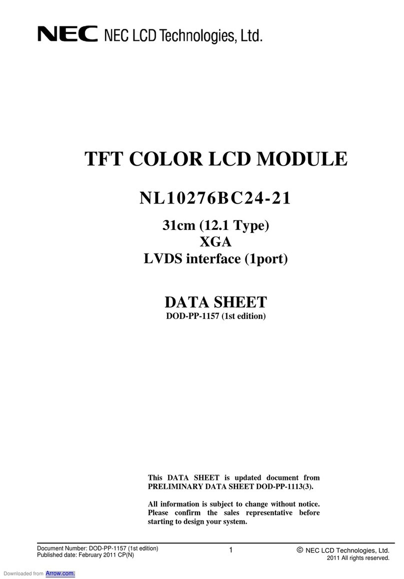
NEC Express5800/B120f User manual

Getting Started describes the procedures necessary for running the server after you
unpack the product. Follow these steps to complete your installation successfully.
SAFETY INDICATION
Refer to Safety Precautions and Regulatory Notices included with the server and follow
the instructions for your safety to setup the server.
CPU Blade
The CPU blade can be equipped with memory module and additional board.
Note: See User's Guide in EXPRESSBUILDER for details.
Important: Make sure that the blade enclosure does not contain any CPU blade. Install
the blade enclosure in the rack. Then, install the CPU blade in the blade
enclosure.
Step 1 Check the accessories.
Unpack the carton box and make sure that you have everything
and that individual components are not damaged.
Note: See the attached packing list.
Important: Keep the EXPRESSBUILDER disc and other attached CD/DVD(s) carefully.
Step 2 Install internal optional devices.
Install internal optional devices.
(Go to Step 3 if you have not purchased options.)
Note: See Installing Internal Optional Devices in the User’s Guide and the guide provided
with the optional device.
Step 3 Install in blade enclosure.
The blade enclosure is the rack mount chassis exclusively used to be equipped with
CPU blades and power supply unit. The blade enclosure is installed in the NEC rack
or NEC-recommended rack conforming to the EIA standard.
Note: Refer to Blade Enclosure User's Guide for details.
Install a CPU blade in blade enclosure according to the following procedure
(1) If an optional slot cover is installed on the slot on which the
CPU blade is to be installed, remove it. Unlock the CPU blade
by holding the lever at the front, pull out the CPU blade, and
then remove the slot cover.
Important: Keep the removed slot cover for future use.
Do not remove the slot cover from any other slot.
(2) Gently place the server on a clean, rigid, and flat desk. Unlock
the eject lever.
(3) Hold the frame of the server so that its MP connector faces the
blade enclosure and the side on which the eject lever is placed
is on the left.
Important: Do not hold the eject lever to install the CPU blade in the blade enclosure. The
eject lever may be disengaged from the CPU blade that causes the CPU blade
to fall down. Or, the eject lever may be bent that causes damage to the CPU
blade.
(4) Align the frame of the CPU blade with the guide rails of the
blade enclosure, and insert the CPU blade into the end of
blade enclosure slowly and carefully.
Important: Make sure that the eject lever hook is hit to the frame of
the blade enclosure, as shown in the figure.
(5) Firmly push the eject lever, holding the frame at the front of the
blade enclosure, and then insert the CPU blade into the blade
enclosure until the eject lever is completely locked.
Step 4 Connect cables.
The keyboard, mouse, display unit, and network devices are connected to the
Connector board in the blade enclosure that is connected with the MP connector at
the rear of the blade enclosure.
The SUV connector on the front of the CPU blade is not used in normal operation.
Use the SUV connector in the following cases:
Using a Flash FDD with the server installed in the blade enclosure
(N8405-016F/016AF/016BF/040F/040AF)
Performing maintenance work
Updating BIOS and firmware
Connect a floppy disk drive, external DVD-ROM drive, keyboard, and mouse
according to the figure shown below. Use the separately priced K410-150(00) SUV
cable (or a standard accessory for the blade enclosure (SIGMABLADE).
However, when using a display unit, keyboard, and mouse connected to the blade
enclosure by using the KVM selection feature of the blade enclosure, do not
connect those devices by way of a SUV cable.
*1 Use the USB hub and external DVD-ROM drive supported by this CPU blade.
Note: See User's Guide in EXPRESSBUILDER and Blade Enclosure User's Guide for
details.
Finally, connect the power cord coming with the power supply unit to the AC inlet of
power supply unit at the rear of the blade enclosure and the AC outlet for 200 to 240
VAC.
Important: The power cord supplied with the power supply unit N8405-017/023(A)/044/055
is exclusively for 200 VAC power. The power cord supplied with the power
supply unit N8405-039(A)/048/054 is exclusively for 240 VAC power. Connect
the power cord only to an AC outlet for 200-240 VAC.
Getting Started!
USB
USB Flash FDD
Self-powered
USB hub *1
First edition, October 2014
E
j
ect leve
r
Monito
r
Keyboard Mouse
Frame
Eject lever hook
Monitor
External DVD-ROM
drive
*1
USB
Ke
y
board Mouse
Go on to the next page.
POWER LED
(green/amber)
STATUS LED
(green/amber/red)
HDD Access LED
(green)
ID LED (blue)
SUV connector
Eject lever
DUMP switch
RESET switch
ID/BMC RESET switch
POWER switch
HDD Access LED
(amber)
* 856-180581-501-00 *
Push down the lock
Step 5 Set up the OS
(1) Turn on the display, the blade enclosure, and then the CPU blades in that order.
If the server starts normally, the NEC logo will appear on the screen.
Important: If an error message is displayed on the screen or beeps are heard
repeatedly after turning on the server, make a note of the displayed
message or the sound of the beeps, and contact your sales representative.
(2) Specify the BIOS settings according to the configuration and usage of the server by
referring to Maintenance Guide and Installation Guide. To change the BIOS
settings, press the F2 key during POST. The factory-default BIOS settings can
usually be used as is.
(3) To install the OS, insert the EXPRESSBUILDER disc into the disk drive on the
server and then restart the server by pressing Ctrl + Alt + Delete keys.
EXPRESSBUILDER starts and the following menu appears.
Tips: EXPRESSBUILDER can be started during POST by pressing the F3 key while the
NEC logo is displayed.
(4) Choose OS installation from the menu. After a while, the following menu is
displayed.
(5) Choose Setup on Home Menu.
(6) See Installation Guide (Windows) to install the OS.
Tips: Installation Guide (Windows) is stored in EXPRESSBUILDER.
When applying a Windows Service Pack to this server, see Service Pack Support in Installation
Guide (Windows).
Step 6 Install the bundled software.
The following software is bundled with this server. Install the software as needed.
Tips: You can create PC for Management by using a general client computer. (You can also
use this server as PC for Management.)
Name Where to
Install Description
NEC ESMPRO
ServerAgentService
Server Monitors the server status.
NEC ESMPRO Agent
Extension
Server Remotely controls the server.
Express Report Service Server Informs the support center of the failure
information.
Express Report Service
(HTTPS)
Server Informs the support center of the failure
information.
NEC ExpressUpdate
Agent
Server Manages and updates the versions of
firmware, software, and other products
installed in the server.
Universal RAID Utility
(URU)
Server Manages and monitors the RAID
controller.
Product Info
Collection Utility
Server Collects information for maintenance.
BMC Configuration Server Sets up BMC.
NEC ESMPRO Manager PC for
Management
Manages the server by integrating with
NEC ESMPRO Agent or other products.
Express Report Service
(MG)
PC for
Management
Informs the support center of the failure
information.
The above bundled software can be installed by using the autorun menu.
Follow the procedure below:
(1) When installing the bundled software in the server, start Windows installed in the
server.
When installing the bundled software in PC for Management, start Windows
installed in the target PC.
(2) Log on to Windows as a user with administrator privileges.
(3) Insert the EXPRESSBUILDER disc into the server.
The following menu is displayed.
(4) Click Integrated Installation on the menu.
(5) Follow the dialog box to install the bundled software.
Trademarks
NEC ESMPRO is a registered trademark of NEC Corporation.
Microsoft, Windows, and Windows Server are either registered trademarks or trademarks of Microsoft
Corporation in the United States and other countries.
All other product, brand, or trade names used in this publication are the trademarks or registered
trademarks of their respective trademark owners.
This guide uses recycled paper.
© NEC Corporation 2014
This document may not be copied or altered without the permission of NEC Corporation.
Windows Service Packs
本指南说明从在打开包装箱,到可以使用本产品的步骤。
请务必遵守本开始指南的指示操作。
安全注意事项
在安装服务器之前,请务必仔细阅读“Safety Precautions and Regulatory Notices”的“使
用时的注意事项”,并遵守注意事项正确地进行安装。
CPU 刀片服务器
可在 CPU 刀片服务器安装内存以及处理器(CPU)、硬盘驱动器、扩展板卡等的可选设备。
提示:有关详情,请参阅保存在 EXPRESSBUILDER 中的用户指南以及刀片服务器机箱の用户指
南。
重要: 请在所有的 CPU 刀片服务器尚未安装的状态下,先将刀片服务器机箱安装到机架上,然
后再安装 CPU 刀片服务器。
步骤
1检查附件。
打开包装箱,确认附件是否齐全。
提示:请参阅附带的“附件清单”。
重要: 请妥善保管附带的 EXPRESSBUILDER 及其他光盘(CD/DVD)。
步骤
2安装内置可选设备。
安装内置可选设备。
(若没有购买可选设备,请直接跳到步骤 3)。
提示:请参阅“用户指南”的“安装内置可选设备”以及可选设备附带的说明书。
步骤
3安装到刀片服务器机箱
刀片服务器机箱是可装载 CPU 刀片服务器以及电源组件等的专用机箱。
将刀片服务器机箱安装到 NEC 的机架或符合 EIA 规格的 NEC 所推荐的机架中。
提示:有关详情请参阅刀片服务器机箱附带的“用户指南”。
按照以下步骤,将 CPU 刀片服务器安装到刀片服务器机箱中。
(1) 若安装服务器的插槽中已安装了可选设备的插槽封盖时,请抓住
前面的控制杆解除锁定后,拉出并拆卸插槽封盖。
重要: ● 请妥善保管拆卸的插槽封盖。
● 除安装服务器的插槽以外,请勿拆卸其他插槽的插槽封盖。
(2) 请在没有灰尘、牢固且平稳的桌子上轻放服务器,解除弹出控
制杆的锁定,使弹出控制杆处于可打开的状态。
(3) 请将有弹出控制杆的面靠左,连接 MP 用的连接器朝向刀片服务器机箱侧,稳定握住
服务器的框架。
重要: 将CPU 刀片服务器安装到刀片服务器机箱上时,请勿握住弹出控制杆。否则,则可能因弹
出控制杆脱落而导致服务器掉落、或因弹出控制杆弯曲而导致服务器破损。
(4) 将服务器的框架沿着刀片服务器机箱的导轨缓慢插入到刀片服
务器机箱内,直到插入刀片服务器机箱的底处为止。
重要: 如图所示,请确认弹出控制杆的挂钩部分已接触到刀片服务器机
箱的框架。
(5) 牢固按下弹出控制杆,用手指按住服务器前面的框架部分,直到
弹出控制杆完全锁定,安装 CPU 刀片服务器。
步骤
4连接连线。
连接键盘、鼠标和显示器以及网络等的设备。请经由服务器背面的与连接 MP 用连接器想连
接的刀片服务器机箱的端口,与各自的设备、外围设备相连接。
另外,日常运作时,并不使用服务器前面备有的 SUV 连接器。
在下述情况下使用 SUV 连接器。
● 在刀片服务器机箱中已安装服务器的状态下使用 Flash FDD 时
(N8405-016F/016AF/016BF/040F/040AF)
● 进行维护作业时
● 进行 BIOS/各种 FW 的更新时
同时连接软盘驱动器以及外接 DVD-ROM 驱动器、键盘和鼠标时,请按照下图所示连接。(请
使用刀片服务器机箱标准附带的 SUV 缆线或另外选购的 K410-150(00)SUV 缆线。)
但是,使用刀片服务器机箱的 KVM 选择功能,然后使用连接到刀片服务器机箱的显示器、
键盘和鼠标时,请勿经由 SUV 线経连接这些设备。
*1 请使用本服务器支持的 USB 集线器以及外接 DVD-ROM 驱动器。
提示:有关详情请参阅保存在 EXPRESSBUILDER 中的“用户指南”以及刀片服务器机箱附
带的“用户指南”。
最后,利用电源组件附带的电源线,连接服务器背面的电源组件的 AC 插座和 AC 200-240V
的插座。
重要: 电源组件 N8405-017/023(A)/044/055 附带的电源线为 AC200V 专用。另外,电源组件
N8405-039(A)/048/054 附带的电源线为 AC 200-240V 专用。
请勿将电源线连接到上述指定电压以外的插座。
USB USB Flash FDD
自供电规格
USB 集线器 *1
鼠标
键盘
USB
外接 DVD-ROM
驱动器 *1
显示器
2014
年
10
月
初版
显示器
键盘
鼠
标
续下一页
POWER 指示灯
(绿色/琥珀色)
STATUS 指示灯
(绿色/琥珀色/红色)
POWER 开关
DUMP 开关
HDD Access
指示灯(绿色)
ID 指示灯(蓝色)
SUV 连接器
RESET 开关
弹出控制杆
ID/BMC RESET
开关
HDD Access
指示灯(琥珀色)
弹出控制杆
按下解除锁定
* 856-180581-501-00 *
框架
弹出控制杆挂钩
步骤
5开启服务器,设置 OS。
(1) 按照显示器、刀片服务器机箱、CPU 刀片服务器的顺序开启电源。
正常启动后,会在显示器上显示出 NEC 标识。
重要: 开启服务器电源后若在显示器上显示出错误消息时,请记录下所显示的消息内容,然后与
当地维护服务公司联系。
(2) 根据服务器配置和系统用途,参阅维护指南以及安装指南,设置 BIOS。
想更改设置时,请在执行 POST 途中按下 F2 键。
通常无需更改 BIOS 设置。
(3) 已安装 OS 时启动已安装的 OS。Windows 时会自动开始安装,请跳至步骤(7)。
(4) 如果未安装 OS,或如果需要重装 OS,请使用 EXPRESSBUILDER。
将EXPRESSBUILDER DVD 放入服务器光驱,然后按下 Ctrl + Alt + Delete 键以重启
服务器。
EXPRESSBUILDER 启动,显示 Boot 菜单。
提示:可从 POST 启动 EXPRESSBUILDER。显示 NEC 标识时,请按下 F3 键。
(5) 从Boot 菜单中选择“OS installation”。选择语言后稍等片刻,会显示出 Home 菜单。
(6) 从Home 菜单中选择 Setup。
(7) 按照《安装指南》中的说明设置 OS。请参考《安装指南(Windows)》。
对服务器应用 Windows Service Pack 时,请参考《安装指南(Windows)》中的“服务包支持”。
步骤
6安装绑定的软件。
服务器绑定了以下软件。请按需安装软件。
提示:可使用普通的客户端计算机创建管理用 PC。(也可使用服务器作为管理用 PC。)
名称 安装位置 概要
NEC ESMPRO
ServerAgentService 服务器 监视服务器状态。
NEC ESMPRO Agent
Extension 服务器 远程控制服务器。
Express Report Service 服务器 可将服务器发生故障时的信息通报给维护服务中心。
Express Report Service
(HTTPS) 服务器 可将服务器发生故障时的信息通报给维修服务中心。
NEC ExpressUpdate
Agent 服务器 可管理和更新服务器的固件、软件等的版本。
Universal RAID Utility
(URU) 服务器 管理、监视RAID控制器。
Product Info
Collection Utility 服务器 可收集维护用的各种信息。
BMC Configuration 服务器 设置BMC。
NEC ESMPRO Manager
管理用PC 可与NEC ESMPRO Agent等联动,对服务器进行管理。
Express Report Service
(MG) 管理用PC 可将服务器发生故障时的信息通报给维护服务中心。
可通过 autorun 菜单安装 Windows 版的绑定软件。
请遵循如下步骤:
(1) 在服务器中安装绑定的软件时,请启动服务器中已安装的 Windows。在管理 PC 中
安装绑定软件时,请启动任意的 PC 中已安装的 Windows。
(2) 以享有管理员权限的用户账号登录 Windows。
(3) 插入 EXPRESSBUILDER DVD。
启动 auto-run 功能,显示如下菜单。
(4) 点击菜单中的 Integrated Installation。
(5) 请按照屏幕上的说明进行安装。
商标
EXPRESSBUILDER、NEC ESMPRO 为NEC 公司的注册商标。
Microsoft、Windows、Windows Server 为Microsoft Corporation 在美国以及其他国家的注册商标或商
标。
其他所记载的公司名称以及产品名称均为各家公司的商标或注册商标。
本资料使用再生纸。
© NEC公司2014
未经 NEC 公司允许,不得对本文档进行复制或转载。
Windows Service Packs

Other manuals for Express5800/B120f

1

Other NEC Computer Hardware manuals

NEC IE-178054-NS-EM1 User manual

NEC

NEC IE-178054-NS-EM1 User manual

NEC SIGMABLADE N8406-017 User manual

NEC

NEC SIGMABLADE N8406-017 User manual

NEC Exastro ITA Operator's manual

NEC

NEC Exastro ITA Operator's manual

NEC Univerge SV9300 User manual

NEC

NEC Univerge SV9300 User manual

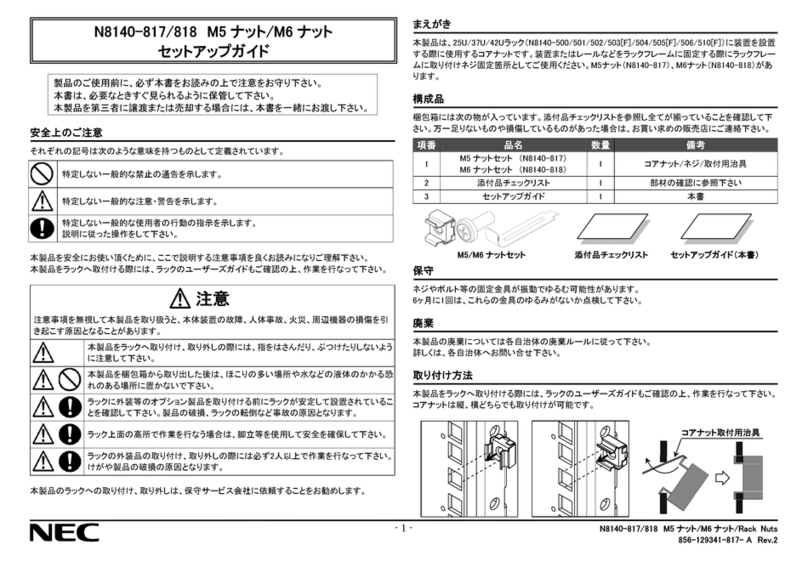
NEC N8140-817 User manual

NEC

NEC N8140-817 User manual

NEC N8151-60 User manual

NEC

NEC N8151-60 User manual

NEC MultiSync M Series User manual

NEC

NEC MultiSync M Series User manual

NEC IE-789835-NS-EM1 User manual

NEC

NEC IE-789835-NS-EM1 User manual

NEC N8151-78A User guide

NEC

NEC N8151-78A User guide

NEC N8151-121 User manual

NEC

NEC N8151-121 User manual

NEC IE-703204-G1-EM1 User manual

NEC

NEC IE-703204-G1-EM1 User manual

NEC IE-703017-MC-EM1 User manual

NEC

NEC IE-703017-MC-EM1 User manual

NEC LED-VP1 User manual

NEC

NEC LED-VP1 User manual

NEC IE-703002-MC User manual

NEC

NEC IE-703002-MC User manual

NEC N8105-58 User manual

NEC

NEC N8105-58 User manual

NEC DS2000 IntraMail How to use

NEC

NEC DS2000 IntraMail How to use

NEC N8146-41 User manual

NEC

NEC N8146-41 User manual

NEC IE-784000-R User manual

NEC

NEC IE-784000-R User manual

NEC IE-V850E-MC User manual

NEC

NEC IE-V850E-MC User manual

NEC N8405-019 User manual

NEC

NEC N8405-019 User manual

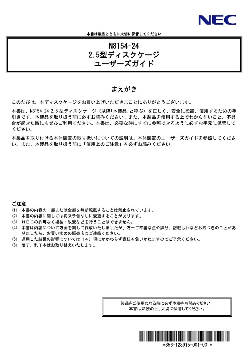
NEC N8154-24 User manual

NEC

NEC N8154-24 User manual

NEC uPD75P308 User manual

NEC

NEC uPD75P308 User manual

NEC IE-789860-NS-EM1 User manual

NEC

NEC IE-789860-NS-EM1 User manual

NEC SB3-DB1 User manual

NEC

NEC SB3-DB1 User manual

Popular Computer Hardware manuals by other brands

Alto BK 2.0 user manual

Alto

Alto BK 2.0 user manual

Thermaltake ARMOR A60 user manual

Thermaltake

Thermaltake ARMOR A60 user manual

MicroBoards Technology CopyWriter BluRay Series user manual

MicroBoards Technology

MicroBoards Technology CopyWriter BluRay Series user manual

Dell Embedded Box PC5000 Service manual

Dell

Dell Embedded Box PC5000 Service manual

Renesas RL78G14 quick start guide

Renesas

Renesas RL78G14 quick start guide

National Instruments PXIe-8106 user manual

National Instruments

National Instruments PXIe-8106 user manual

Lanberg AK-1502-B manual

Lanberg

Lanberg AK-1502-B manual

DG FPGA Setup

DG

DG FPGA Setup

ICP DAS USA PCI-AD64 quick start

ICP DAS USA

ICP DAS USA PCI-AD64 quick start

YASKAWA VIPA System MICRO M13-CCF0000 manual

YASKAWA

YASKAWA VIPA System MICRO M13-CCF0000 manual

JM Precision HP9830A Assembly manual

JM Precision

JM Precision HP9830A Assembly manual

andrews ASF21 Operating instructions  & safety guide

andrews

andrews ASF21 Operating instructions & safety guide

Sonnet Encore ST G4 quick start guide

Sonnet

Sonnet Encore ST G4 quick start guide

Zenith Data Systems Z-100 Series installation manual

Zenith Data Systems

Zenith Data Systems Z-100 Series installation manual

Arctic ACCELERO XTREME PLUS installation manual

Arctic

Arctic ACCELERO XTREME PLUS installation manual

Freescale Semiconductor EVBCRTOUCH quick start guide

Freescale Semiconductor

Freescale Semiconductor EVBCRTOUCH quick start guide

Compex WPQ618 Hardware guide

Compex

Compex WPQ618 Hardware guide

Imagenation PXD1000 quick start guide

Imagenation

Imagenation PXD1000 quick start guide

manuals.online logo
manuals.online logoBrands
  • About & Mission
  • Contact us
  • Privacy Policy
  • Terms and Conditions

Copyright 2025 Manuals.Online. All Rights Reserved.