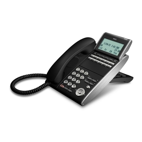
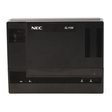
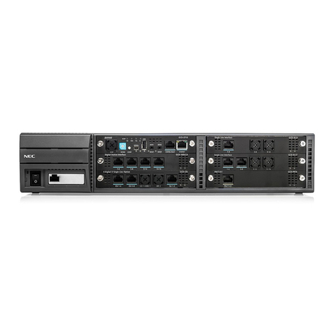
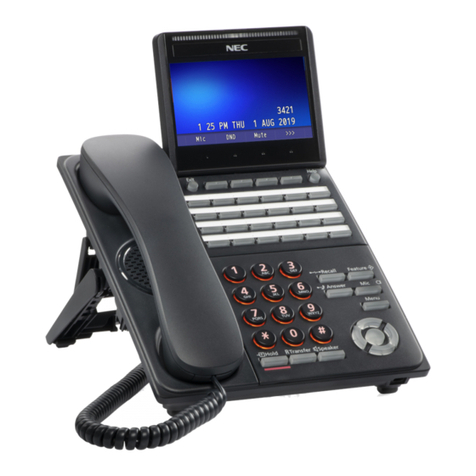
manuals.online logo
Brands
  1. Home
  2. •
  3. Brands
  4. •
  5. NEC
  6. •
  7. Conference System
  8. •
  9. NEC UNIVERGE SL2100 User manual

NEC UNIVERGE SL2100 User manual

Hardware Manual
GVT-010793-301-00NA
ISSUE 4.0
September 2021
631-862-1339
Before use
•
Please read this manual carefully before operating this product and save this manual for future
use.
Copyright
NEC Platforms, Ltd. reserves the right to change the specifications, functions, or features at
any time without notice.
NEC Platforms, Ltd. has prepared this document for use by its employees and customers.
The information contained herein is the property of NEC Platforms, Ltd. and shall not be
reproduced without prior written approval of NEC Platforms, Ltd.
Android is a trademark of Google LLC
Bluetooth is a registered trademark of Bluetooth SIG Inc. and licensed to our company
under license agreement.
Windows is a registered trademark of Microsoft Corporation. Plantronics is a trademark or
registered trademark of Plantronics, Inc. or its subsidiaries in the United States and other
countries and is licensed to NEC Platforms, Ltd. All other brand names and product names
referenced in this document are trademarks or registered trademarks of their respective
companies.
Copyright 2017 - 2021
NEC Platforms, Ltd.
ISSUE 4.0 SL2100
Hardware Manual 1
TABLE OF CONTENTS
Chapter 1 Introduction
COPYRIGHT.......................................................................................................................................... 2
TABLE OF CONTENTS .......................................................................................................................1
PRODUCT LIABILITY.........................................................................................................................4
REGULATORY ....................................................................................................................................10
CHAPTER 1. INTRODUCTION .......................................................................................................16
Section 1 GENERAL INFORMATION ..................................................................................................................16
Section 2 EQUIPMENT LIST...............................................................................................................................18
2.1 Chassis/CPU and Boards For Chassis Expand ........................................................................................21
2.2 Backup Battery Unit...............................................................................................................................22
2.3 Trunk/Extension/ISDN Expansion Interface Boards ..............................................................................23
2.4 Optional Interface Boards .....................................................................................................................24
2.5 Multiline Telephones and Optional Equipment .....................................................................................25
2.6 Wireless DECT Telephones.....................................................................................................................30
2.7 Call Logging Unit ....................................................................................................................................30
Section 3 SYSTEM CAPACITY.............................................................................................................................32
3.1 System Capacity.....................................................................................................................................32
3.2 Chassis Capacity.....................................................................................................................................33
CHAPTER 2. INSTALLATION.........................................................................................................37
Section 1 INSTALLING THE MAIN & EXPANSION CHASSIS .................................................................................37
1.1 Before Installing the Chassis..................................................................................................................37
1.2 Installing the Main Chassis (IP7[ ]-4KSU-C1)..........................................................................................38
1.3 CPU Board (IP7[ ]-CPU-C1).....................................................................................................................38
1.4 Chassis Dimensions................................................................................................................................42
1.5 Wall-Mounting the Chassis....................................................................................................................42
1.6 Rack Mounting the Chassis....................................................................................................................48
1.7 Installing the Expansion Chassis ............................................................................................................48
1.8 Grounding and AC Cabling.....................................................................................................................55
Section 2 INSTALLING THE EXTERNAL BACKUP BATTERY ..................................................................................59
2.1 General ..................................................................................................................................................59
2.2 Unpacking..............................................................................................................................................59
2.3 Battery Box Dimensions.........................................................................................................................60
2.4 Battery Specifications ............................................................................................................................60
2.5 Battery Installation ................................................................................................................................60
2.6 Mounting the IP4WW-Battery Box........................................................................................................66
2.7 IP4WW-Battery Box to Chassis Connection...........................................................................................72
2.8 IP4WW-Battery Box Fuse Replacement ................................................................................................73
ISSUE 4.0 SL2100
Hardware Manual 2
Section 3 INSTALLING THE EXPANSION INTERFACE BOARDS ............................................................................78
3.1 General ..................................................................................................................................................78
3.2 Unpacking..............................................................................................................................................78
3.3 Mounting the Expansion Interface Board..............................................................................................78
3.4 Extension/Trunk Cabling........................................................................................................................83
Section 4 INSTALLING THE OPTIONAL INTERFACE BOARDS ..............................................................................92
4.1 VoIP Board (VOIPDB-C1) ........................................................................................................................92
4.2 Installing the SD Card (SDVMS/SDVML) ................................................................................................97
Section 5 INSTALLING THE MULTILINE TELEPHONES AND OPTIONAL TERMINALS ............................................98
5.1 Installing the Digital Multiline Telephones.............................................................................................98
5.2 Installing the IP Multiline Telephone (IP7[ ]-8IPLD-C1 TEL) .................................................................103
5.3 Installing the DSS Console ...................................................................................................................107
5.4 Installing the Headset..........................................................................................................................110
5.5 Installing the Doorphone Box, Security Sensor Device (locally procure).............................................110
5.6 Installing the Door Unlock Devices ......................................................................................................114
5.7 Installing the External Paging Speaker/External MOH/BGM Sources .................................................115
5.8 SMDR (Station Message Detail Recording)..........................................................................................116
5.9 Wireless Headset Adapter (WHA) .......................................................................................................117
5.10 Installing the IP4WW-12/24TXH-[ ] Multiline Terminals and options..................................................121
5.11 Installing the IP Multiline Telephone (ITK-8LCX-1) ..............................................................................122
5.12 Installing the ITX-3370-1( )(BK) TEL .....................................................................................................127
5.13 Installing the ITX-1615-1W(BK) TEL .....................................................................................................127
Section 6 INSTALLING WIRELESS DECT TELEPHONES .....................................................................................128
6.1 Installing the DTL-8R-1 Cordless DECTTelephone................................................................................128
6.2 Installing the DTL-RPT-1 Cordless DECT Telephone REPEATER.............................................................138
6.3 Installing the DTL-RPT-2 Cordless DECT Telephone REPEATER.............................................................145
6.4 Install the DTZ-8R-1 CORDLESS DECT Telephone.................................................................................154
6.5 Installing the ML440 and AP20 Wireless DECT Telephone ..................................................................162
Section 7 INSTALLING OPTIONAL EQUIPMENT ...............................................................................................169
7.1 NEC Digital Call Logger.........................................................................................................................169
7.2 NEC IP Call Logger................................................................................................................................172
7.3 NEC Digital Player Requirements.........................................................................................................179
7.4 NEC Digital Player/Recorder Installation .............................................................................................180
CHAPTER 3. SYSTEM START UP...............................................................................................185
Section 1 SYSTEM START UP ...........................................................................................................................185
1.1 Before Starting Up the System ............................................................................................................185
1.2 Starting Up the System........................................................................................................................185
Section 2 PROGRAMMING MODE ..................................................................................................................188
2.1 Entering the Programming Mode........................................................................................................188
2.2 Exiting the Programming Mode...........................................................................................................188
2.3 Saving (Backup) the Customer Data ....................................................................................................189
2.4 Loading the Customer Data.................................................................................................................189
Section 3 SYSTEM SHUT DOWN......................................................................................................................191
3.1 Powering Off the System.....................................................................................................................191
3.2 Resetting the System...........................................................................................................................191
CHAPTER 4 MAINTENANCE.......................................................................................................193
Section 1 LITHIUM BATTERY REPLACEMENT ...................................................................................................193
ISSUE 4.0 SL2100
Hardware Manual 3
1.1 General ................................................................................................................................................193
1.2 Lithium Battery Specification...............................................................................................................193
1.3 Replacing the Lithium Battery .............................................................................................................193
Section 2 MAIN SOFTWARE UPGRADING .......................................................................................................196
2.1 General ................................................................................................................................................196
2.2 Before Upgrading the Main Software..................................................................................................196
2.3 Main Software Version Confirmation ..................................................................................................196
2.4 Upgrading the Main Software .............................................................................................................197
Section 3 LED INDICATIONS............................................................................................................................204
CHAPTER 5 SPECIFICATIONS....................................................................................................207
Section 1 SYSTEM CAPACITY...........................................................................................................................207
Section 2 SYSTEM SPECIFICATIONS.................................................................................................................209
2.1 General Precautions ............................................................................................................................209
2.2 Environmental Requirements..............................................................................................................209
2.3 Operating Conditions...........................................................................................................................209
2.4 Site Requirements ...............................................................................................................................209
2.5 AC Power Requirement .......................................................................................................................209
2.6 Electrical Specifications <Power Supply> (Chassis) .............................................................................210
2.7 CPU ......................................................................................................................................................210
2.8 Traffic Capacity ....................................................................................................................................210
2.9 IP Terminal Power Chart ......................................................................................................................211
2.10 IEEE802.3af/802.3at Class Specification..............................................................................................211
2.11 SLT Ring Signal Specification ................................................................................................................211
2.12 Mechanical Specifications ...................................................................................................................211
2.13 Optional Unit Mechanical Specifications.............................................................................................212
2.14 Doorphone Interface Specifications ....................................................................................................212
2.15 General Purpose/Door Unlock Relay Specifications............................................................................213
2.16 External Paging Output Specifications.................................................................................................213
2.17 BGM/ExMOH Source Input Specifications...........................................................................................213
2.18 External Sensor Device Interface Specifications..................................................................................213
2.19 CPU Board LAN Port Specifications......................................................................................................213
2.20 Cabling Requirements .........................................................................................................................214
2.21 Cable Requirements.............................................................................................................................214
ISSUE 4.0 SL2100
PRODUCT LIABILITY 4
PRODUCT LIABILITY
USING THE EQUIPMENT SAFELY
The following safety information describes how to avoid injuries while working with the equipment and
how to prevent damage to the equipment. Learn the meaning of the following symbols and then read
this section carefully before using the equipment.
SYMBOL
DESCRIPTION
DANGER
Incorrect use of the equipment may cause personal injury or death.
WARNING
Incorrect use of the equipment may cause personal injury or a serious system fault.
CAUTION
Incorrect use of the equipment may limit the system performance or cause the system to
fail.
The telephone system can only be used in NEC-designated countries.
If a system-down, malfunction, defect or external factor such as an electrical failure indirectly causes a loss of profit, the com-
pany (or affiliates) will not be held responsible.
The goal is to produce a comprehensive and accurate manual. However, if errors or omissions are found in this manual,
please notify NEC Corporation.
If the system requires installation or repair, contact the dealer or its service technician.
Carefully read all the manuals that relate to the system.
SAFETY CONSIDERATIONS
The following describes the safety considerations that must be observed before using the system, the
powerrelated equipment and the peripheral equipment, such as consoles, the Main Distribution Frame
(MDF), telephones, PCs, printers, etc.
DANGER
If the system emits smoke or a burning, acrid odor, immediately turn off the system power.
Operating the system in this state might cause a fire, an electrical shock, or a system failure. After
turning off the power and confirming that the smoke has disappeared, contact the dealer.
If any equipment, such as the system, the main power source, a cabinet or peripheral equipment tips
over, turn off the power and contact the dealer.
ISSUE 4.0 SL2100
PRODUCT LIABILITY 5
DANGER
Plastic knockout panels are only allowed to be cut using side cutters. Box cutter/knife is not allowed to
be used.
If liquid reaches the inside of the system or the main power source, turn off the power. Operating the
system in this state might cause a fire, an electrical shock, or a system failure.
P W R
Do not touch the internal parts of the main power source to disassemble or configure it. This action
may cause a fire, an electrical shock or a system failure.
NEC Corporation does not take any responsibility for disassembled or reconfigured equipment.
Do not put any container objects (such as a vase or a cup) on the main power source or any peripher-
al equipment. It might cause a fire, an electrical shock or a system failure.
Be sure to use cables designated by NEC or cables attached to the equipment. If cables are not des-
ignated particularly, choose cables with considering safety and transmission performance carefully.
Ask the dealer or your local agency if needed.
Do not tamper with, modify, forcefully bend, forcefully remove or twist an electrical cord or any wiring
to or from the system, the main power source or any peripheral equipment. It might cause a fire, an
electrical shock, or a system failure. If the wiring is damaged, contact the dealer.
dust
Correctly insert all of the electrical plugs into the electrical outlets. Before inserting a plug into an elec-
trical outlet, ensure that there is no dust on the plug’s blades. If there is dust on a blade, it might
cause a fire.
Do not use power other than the power that was designated for the system when it was installed.
PWR
Do not attempt to repair or move the main power source without assistance from the dealer.
Do not put any metal or combustible objects into a vent of the system, the main power source, or any
peripheral equipment. Operating the system in this state might cause a fire, an electrical shock, or a
system failure. If this occurs, turn off the power and contact the dealer.
Be careful when using any peripheral equipment’s Liquid Crystal Display (LCD). If the liquid leaks, it
can be harmful to the user and to the system.
?
Before connecting any non-NEC, customer-provided equipment, check with the supplier to ensure
that the equipment is compatible. If the supplier cannot confirm the compatibility, do not connect the
equipment. Connecting incompatible equipment might cause a fire or an electrical shock.
PWR
ISSUE 4.0 SL2100
PRODUCT LIABILITY 6
WARNING
Do not place any object on the system or the main power source. If the object falls, it might cause
personal injury or damage to the equipment.
When removing a plug from an outlet, be sure to grip the plug, not the cord. Gripping the cord to re-
move the plug could cause a fire or an electrical shock to occur.
If lightning causes a fault, contact the dealer.
Provide the appropriate temperature, humidity, and ventilation on an around-the-clock basis. For ex-
ample, at a height that is one meter (3.28 feet) above the floor, the temperature should be between
20°C and 25°C (68°F to 77°F) and the humidity should be approximately 50%.
ATTENTION
Contents
Static Sensitive
Handling
Precautions Required
Take appropriate anti-static measures so that the other end of the anti-static kit can be connected to
the metal part of the frame.
Observe the following precautions when using any optional batteries:
•The system’s emergency back-up battery may be a rechargeable lead battery. Check the emergen-
cy battery for an electrical failure.
•Battery acid (electrolyte) is extremely harmful to human skin and eyes. If battery acid contacts skin,
wash the affected area with soap and water. If battery acid contacts the eyes, flush the eyes with
water. In either event, seek medical attention. If there is battery acid on a cloth, use water to wash
the battery acid from the cloth.
•Do not intentionally short batteries. Do not put the battery near a fire or in a fire. Do not disassem-
ble the battery, drop it or knock it against another object.
•The battery’s life expectancy is affected by its environment. The normal battery life is approximately
three years. If the battery is used in an outdoor setting and is exposed to high temperatures, its life
expectancy drops to approximately one year.
•Perform periodic diagnostic tests and maintenance procedures on the emergency battery and its
terminals to ensure their readiness. If there is a power failure and the emergency battery is not
ready, then the system will not work. Additionally, a damaged or dead battery, or terminals that
need replacement might cause battery acid to leak, which might cause smoke or a fire. The battery
and terminals are periodic replacement parts (the cost is chargeable to the customer). A service
contract, with the supplier or service technician, to perform routine maintenance for the battery is
recommended.
Do not touch peripheral equipment with wet hands. Do not allow any liquid to touch any of the periph-
eral equipment.
Do not touch the printer’s internal components when replacing disposables such as a cartridge or a
ribbon. Ensure that the printer is turned off and that it is not hot in order to prevent burns from any
accidental contact with the internal components.
Do not drop the peripheral equipment or knock it against another object. These actions might cause
an equipment failure.
ISSUE 4.0 SL2100
PRODUCT LIABILITY 7
CAUTION
Thinner
Do not use benzine, thinner or alcohol for cleaning. When removing dust and dirt, put diluted, mild
detergent on a cloth and then wring out the cloth. Remove the dust and dirt with the cloth and then
wipe the cleaned area with a dry cloth.
Do not place any equipment in the following environments:
•Locations that are exposed to direct sunlight
•Locations where the moisture level exceeds the allowed level
•Locations where the equipment might be exposed to water, oil, orchemicals
•Locations with very low temperatures, such as in a walk-in cooler orfreezer
•Locations that are exposed to Electromagnetic Interference (EMI) from devices such as television
sets and two-way radios
•Locations that receive illegal electric waves
The life expectancies of the system and the main power source will be shortened if placed in a loca-
tion that is affected by hydrogen sulfide or salt, such as a seaside area.
Installation Environment
Consider the following items before the installation.
Stability
WARNING
Install the system with anchor bolts to prevent constant movement or vibration, such as from a nearby
motor or automatic door, and to resist catastrophic movement from natural disasters, such as an
earthquake. If the system moves or falls, an injury could occur.
Floor, Wall and Ceiling
WARNING
The wall and ceiling materials must be resistant to Electrostatic Discharge (ESD) and provide heat
insulation. Since the battery’s life expectancy depends on the ambient temperature, the room where
the battery is installed must be well ventilated and vented to the outside. Check the battery specifica-
tions to determine if the battery can or cannot be installed near a motor or a power transformer.
The floor material that is under and around the system must be resistant to ESD.
Windows
CAUTION
Keep all of the windows closed if the location is affected by dust, sea breeze or corrosive gas. Cur-
tains or blinds are necessary to avoid direct sunlight.
Fire Extinguisher
WARNING
Place a fire extinguisher for electrical fires (such as a carbon-gas fire extinguisher or a halon-gas fire
extinguisher) near the system. It is recommended that the room also be equipped with an automatic
fire-detection system. In the event of smoke and fire, turn off the main power source and the backup
battery, then use the fire extinguisher to put out the fire while trying to avoid inhaling any smoke.
ISSUE 4.0 SL2100
PRODUCT LIABILITY 8
Safety Environment
WARNING
Consider measures to deal with disasters (such as fires, floods and earthquakes) and to ensure the
safety of the staff.
Regularly clean the room or rooms where the switching equipment resides.
Do not spray any insecticides directly on the equipment (insecticides can adversely affect the switch-
ing equipment).
Air Conditioning Facilities
WARNING
The system and the air conditioning system must be installed separately and have separate power
sources.
To prevent an electromagnetic arc from causing noise, attach a surge-limiting capacitor and resistor
on the air conditioner’s electromagnetic switch’s coil.
It might be necessary to adjust the ventilation so the air conditioning is equally effective throughout
the equipment room.
Do not place the system in a location where condensation might fall from an air conditioner or a duct.
Do not place the system in a location where hot and humid air is exhausted, as this might damage the
system.
Lightning Strikes
WARNING
The grounding system must protect the system, MDF, main power source, PCPro, printer, modems,
etc. from damage caused by lightning strikes and electrical surges.
All the grounding conductors must have a resistance of less than one Ω to bring a zerovoltage refer-
ence to the system components.
To achieve this, the following ground conductors must connect to the Primary Ground Bar:
•The Earth Ground (E) from the Rectifier
•The Frame Ground (FE) from the system
•The Power Ground (PE) from the system, through the Rectifier
•The Frame Ground (FE) from the MDF
•The AC service outlets, with plug outlets, for the PCPro, printer, modems and any measurement
devices, such as a protocol analyzer.
Electromagnetic Interference
CAUTION
When installing an additional device in the vicinity of the system, observe the installation and operat-
ing instructions for the device.
Otherwise, EMI noise from the device may cause a malfunction of the system.
Disposables and Periodic-replacement Parts
CAUTION
Many parts, such as batteries, backup batteries, fuses and displays need to be replaced on a periodic
basis. In the event of sudden traffic, a part that is past due for replacement might lead to a system
failure and damage to the system.
A service contract with the dealer or its service technician to monitor the replacement cycles and to
supply the replacement parts and the necessary disposables is recommended.
ISSUE 4.0 SL2100
PRODUCT LIABILITY 9
MEMO
ISSUE 4.0 SL2100
Regulatory 10
Regulatory
CERTIFICATION LABELS
The product certification labels can be found on the outside surface of the main unit. These labels
have important safety and regulatory compliance information.
SAFETY INFORMATION
This equipment has been certified by Canadian Standards Association (CSA) and found to comply
with all applicable safety requirements for North America:
•CAN/CSA C22.2 No.60950-1-07+ Safety of Information Technology Equipment --
A1:2011+A2:2014
Part l: General Requirements
RADIO FREQUENCY INTERFERENCE
In compliance with FCC Part 15 rules, the following statements are provided.
NOTE
This equipment has been tested and found to comply with the limits for a Class B digital device,
pursuant to part 15 of the FCC Rules. These limits are designed to provide reasonable protection
against harmful interference in a residential installation. This equipment generates, uses and can
radiate radio frequency energy and, if not installed and used in accordance with the instructions, may
cause harmful interference to radio communications. However, there is no guarantee that interference
will not occur in a particular installation. If this equipment does cause harmful interference to radio or
television reception, which can be determined by turning the equipment off and on, the user is
encouraged to try to correct the interference by one or more of the following measures:
•Reorient or relocate the receiving antenna.
•Increase the separation between the equipment and receiver.
•Connect the equipment into an outlet on a circuit different from that to which the receiver is connected.
•Consult the dealer or an experienced radio/TV technician for help.
CAUTION
Changes or modifications not expressly approved by the party responsible for compliance could void
the user's authority to operate the equipment.
For Canada: CAN ICES-3(B)/NMB-3(B)
ISSUE 4.0 SL2100
Regulatory 11
TELEPHONE TERMINAL EQUIPMENT (TTE)
This equipment complies with Part 68 of the FCC rules and requirements adopted by ACTA
(Administrative Council for Terminal Attachments). On the main chassis of this equipment is a label
that contains, among other information, the FCC Registration Number (or product identifier) in the
format: US:AAAEQ##TXXXX. If requested, this number must be provided to the telephone company.
The telephone company may make changes in its facilities, equipment, operations or procedures that
could affect the operation of the equipment. If this happens the telephone company will provide
advance notice in order for you to make necessary modifications to maintain uninterrupted service.
The Ringer Equivalence Number (REN) applies to analog telephone lines (or trunks) and is used to
determine the maximum number of devices that may be connected to a telephone line. Excessive
devices on a telephone line may result in the devices not ringing in response to an incoming call. In
most but not all areas, the sum of RENs should not exceed five (5.0). To be certain of the number of
devices that may be connected to a line, as determined by the total RENs, contact the local telephone
company. The REN for this product is part of the FCC Registration Number (or product identifier) in the
format: US:AAAEQ##TXXXX. The digits represented by ## are the REN without a decimal point (e.g.,
03 is a REN of 0.3). The REN and the FCC Registration Number for this product are provided below.
Connection to party line service is subject to state tariffs. Contact the state public utility commission,
public service commission or corporation commission for information.
For single and two-line equipment that connects to the telephone network via a plug and jack, the plug
and jack used to connect this equipment to the premises wiring and telephone network must comply
with the applicable FCC Part 68 rules and requirements adopted by ACTA. A compliant telephone cord
and modular plug may be provided with this product. It is designed to be connected to a compatible
modular jack that is also compliant. See installation instructions for details.
TELEPHONE/SERVICE PROVIDER COMPANY NOTIFICATION
Before connecting this telephone system to the telephone network, the telephone company may
require the following information.
Site Telephone Number
FCC Registration Number
US: NIFMF03ASL2100
Ringer Equivalence Number (REN)
0.3A
Service Order Codes (SOC)
9.0F (analog), 6.0P (digital)
Facility Interface Codes (FIC)
02LS2, 04DU9-BN, 04DU9-DN, 04DU9-1KN, 04DU9-1SN
USOC Jacks
RJ11C, RJ48C, RJ61X
ALARM DIALING EQUIPMENT
If the SL2100 system is used with alarm dialing equipment, ensure that the installation of the SL2100
does not disable your alarm dialing equipment. If you have questions about what will disable alarm
equipment, consult your telephone company or a qualified installer.
ELECTRICAL SAFETY ADVISORY
Telephone companies report that electrical surges, typically lightening transients, are very destructive
to customer terminal equipment connected to AC power sources. This has been identified as a major
nationwide problem. Therefore it is recommended that you use a surge arrestor on the AC power
input.
ISSUE 4.0 SL2100
Regulatory 12
INCIDENCE OF HARM
Should this product cause harm to the telephone network, the telephone company will notify you in
advance that temporary discontinuance of service may be required. If advance notice is not practical,
you will be notified as soon as possible. Additionally the telephone company may request that you
disconnect the equipment until the problem is resolved. Also, you will be advised of your right to file a
complaint with the FCC, should you feel it is necessary.
REPAIR SERVICE REQUIREMENTS
If the equipment malfunctions, all repairs must be performed by an authorized agent of NEC
Corporation of America. The user requiring service is responsible for reporting the need for service to
an NEC Corporation of America authorized agent or to NEC Corporation of America.
HEARING AID COMPATIBILITY
NEC Multiline Terminals and NEC Single Line Telephones that are provided for this system are
hearing aid compatible (HAC). The manufacturer of other Single Line Telephones for use with the
system must provide notice of hearing aid compatibility to comply with FCC rules that prohibit the use
of non-hearing aid compatible telephones.
OTHER
TOLL RESTRICTION AND LEAST COST ROUTING EQUIPMENT
The software contained in the SL2100 to allow user access to the network must be upgraded torecognize
newly established network area codes and exchange codes as they are placed into service.
Failure to upgrade the premises system or peripheral equipment to recognize the new codes as they
are established will restrict the customer and the customer's employees from gaining access to the
network and these codes.
EQUAL ACCESS REQUIREMENTS
This equipment is capable of providing users access to interstate providers of
operator services through the use of access codes. Modification of this
equipment by call aggregators to block access dialing codes is a violation of the
Telephone Operator Consumers Act of 1990.
DIRECT INWARD DIALING (DID)
VOICE ANNOUNCEMENT/MONITORING OVER DID LINES
When using the Voice Announcement feature to eavesdrop or record sound
activities at the other end of the telephone line may be illegal under certain
circumstances and laws. See section below, RECORDING CONVERSATIONS
or MONITORING AUDIO, for more details.
ANSWER SUPERVISION
Allowing this equipment to be operated in such a manner as to not provide for
proper Answer Supervision is a violation of Part 68 of the FCC Rules. Proper
Answer Supervision is when:
ISSUE 4.0 SL2100
Regulatory 13
1. This equipment returns answer supervision to the Public Network when DID calls are:
•Answered by the called station
•Answered by the Attendant
•Routed to a recorded announcement that can be administered by the Customer Premise Equipment (CPE)
user
•Routed to a dial prompt
2. This equipment returns answer supervision on all DID calls forwarded to the Public Network. Permissible
exceptions are:
•A call is unanswered
•A busy tone is received
•A reorder tone is received.
RECORDING CONVERSATIONS or MONITORING AUDIO
The use of monitoring, recording, or listening devices to eavesdrop, monitor,
retrieve, or record telephone conversations or other sound activities, whether
or not contemporaneous with transmission, may be illegal in certain
circumstances under federal or state laws. This includes using the Voice
Announcement feature for recording or monitoring purposes. Legal advice
should be sought prior to implementing any practice that monitors or records
any telephone conversation. Some federal and state laws require some form of
notification to all parties to a telephone conversation, such as using a beep
tone or other notification methods or requiring the consent of all parties to the
telephone conversation, prior to monitoring or recording the telephone
conversation. Some of these laws incorporate strict penalties.
MUSIC ON HOLD
In accordance with U.S. Copyright Law, a license may be required from the
American Society of Composers, Authors and Publishers (ASCAP), or other
similar organizations, if radio, television broadcasts, music, or works other
than material not in the public domain are transmitted through the Music On
Hold feature of this telecommunications system. NEC Corporation of America,
hereby disclaims any liability arising out of the failure to obtain such a license.
CANADA - TELEPHONE TERMINAL APPARATUS
Notice:
This equipment meets the applicable Innovation, Science and Economic Development Canada (ISED)
Terminal Equipment Technical Specifications. This is confirmed by the registration number. The
abbreviation, IC, before the registration number signifies that registration was performed based on a
Declaration of Conformity indicating that ISED technical specifications were met. It does not imply that
ISED approved the equipment.
Avis:
Le présent matériel est conforme aux spécifications techniques applicables d'Innovation, Sciences et
Développement économique Canada (ISED) au matériel terminal. Cette conformité est confirmée par
le numéro d'enregistrement. Le sigle IC, placé devant le numéro d'enregistrement, signifie que
l'enregistrement s'est effectué conformément à une déclaration de conformité et indique que les
spécifications techniques d'ISED ont été respectées. Il n'implique pas qu'ISED a approuvé le matériel.
Notice:
ISSUE 4.0 SL2100
Regulatory 14
The Ringer Equivalence Number (REN) for this terminal equipment is 0.3. The REN assigned to each
terminal equipment provides an indication of the maximum number of terminals allowed to be
connected to a telephone interface. The termination on an interface may consist of any combination of
devices subject only to the requirement that the sum of the Ringer Equivalence Numbers of all the
devices does not exceed five.
Avis:
L'indice d'équivalence de la sonnerie (IES) du présent matériel est de 0.3. L'IES assigné à chaque
dispositif terminal indique le nombre maximal de terminaux qui peuvent être raccordés à une interface
téléphonique. La terminaison d'une interface peut consister en une combinaison quelconque de
dispositifs, à la seule condition que la somme d'indices d'équivalence de la sonnerie de tous les
dispositifs n'excède pas 5.
ISED Registration Number: IC: 140L-SL2100
Ringer Equivalence Number (REN): 0.3
BATTERY DISPOSAL
The SL2100 system includes the batteries listed below. When disposing of these batteries, Chassis,
and/or Unit, you must comply with applicable federal and state regulations regarding proper disposal
procedures.
Unit Name
Type of Battery
Quantity
Note
IP7[ ]-CPU-C1
Lithium
1
External Battery
(IP4WW-Battery Box)
Sealed Lead
2 per IP4WW-Battery Box
DTZ-8R-1 Cordless Handset
Ni-MH
1
ML440 Wireless Handset
Lithium-ion
1
The SL2100 IP7[ ]-CPU-C1 provides Real-Time Clock backup for approximately three years. The
Lithium battery should be replaced every two years.
IMPORTANT SAFEGUARDS FOR BATTERY DISPOSAL
DO NOT PLACE USED BATTERIES IN YOUR REGULAR WASTE! THE PRODUCT YOU
PURCHASED CONTAINS LITHIUM, SEALED LEAD BATTERIES. LITHIUM, SEALED LEAD
BATTERIES MUST BE COLLECTED, RECYCLED, OR DISPOSED OF IN AN ENVIRONMENTALLY
SOUND MANNER.
The incineration, landfilling or mixing of sealed lead batteries with the municipal solid waste stream is
PROHIBITED BY LAW in most areas. Contact your local solid waste management officials for other
information regarding the environmentally sound collection, recycling, and disposal of the battery.
Sealed lead batteries must be returned to a federal or state approved sealed lead battery recycler.
This may be where the batteries were originally sold or a local seller of automotive batteries. Contact
your local waste management officials for other information regarding the environmentally sound
collection, recycling and disposal of the battery contained in this product.
The packaging for the SL2100 system contains the following labels regarding proper disposal.
ISSUE 4.0 SL2100
Regulatory 15
PRODUCT DISPOSAL INFORMATION
For Countries in the European Union
The symbol depicted here has been affixed to your product to inform you that electrical and electronic
products should not be disposed of as municipal waste.
Electrical and electronic products including the cables, plugs and accessories should be disposed of
separately to allow proper treatment, recovery and recycling. These products should be taken to a
designated facility where the best available treatment, recovery and recycling techniques are
available. Separate disposal has significant advantages: valuable materials can be re-used and it
prevents the dispersion of unwanted substances into the municipal waste stream. This contributes to
the protection of human health and the environment.
Please be informed that a fine may be imposed for illegal disposal of electrical and electronic products
via the general municipal waste stream.
To facilitate separate disposal and environmentally sound recycling arrangements have been made for
local collection and recycling. If your electrical and electronic products must be disposed of please
refer to your supplier or the contractual agreements that your company has made upon acquisition of
these products.
BATTERY INFORMATION
Defective or exhausted batteries should never be disposed of as municipal waste. Return old batteries
to the battery supplier, a licensed battery dealer or a designated collection facility. Do not incinerate
batteries. This product uses Lithium batteries. Do not use any other type.
For an overview of the location of batteries used in these systems, the battery replacement or removal
instructions, please refer to the SL2100 System Hardware Manual.
CONTAINS SEALED LEAD BATTERY.
BATTERY MUST BE RECYCLED. MUST NOT
BE DISPOSED OF IN MUNICIPAL WASTE.
Pb
ISSUE 4.0 SL2100
GENERAL INFORMATION 16
Chapter 1. Introduction
Section 1 GENERAL INFORMATION
Prior to installation, download from NTAC Website the latest version of the SL2100 Main CPU
Software, available free of charge. The latest software will include security improvements, feature
enhancements and bug fixes. Latest software is required to maintain compliance with local and
federal laws.
The SL2100 system is a progression from SL1000/SL1100 system and is newly provide a legacy and
IP communication system for All-In-One Small Box to support Small and Medium Business with easy
installation and easy operation.
The SL2100 has new designed Multiline Terminals and a new small compact chassis comes with the
four universal slots and one CPU/EXIFE slot for Slot-In design chassis.
The SL2100 system enable to expand up to three chassis (one Main and two Expansion chassis) by
bus connection and provides a maximum of 36 analog trunks and 72 Multiline Terminals also equipped
to support IP Networking, Digital Networking (BRI/PRI, T1/E1) and IP Trunks or IP extensions.
ISSUE 4.0 SL2100
GENERAL INFORMATION 17
Figure 1-1 System Configuration
ISSUE 4.0 SL2100
EQUIPMENT LIST 18
Section 2 EQUIPMENT LIST
Table 1-1 Hardware Equipment List
Category
Stock
Number
Equipment Name
Equipment Description
Note
Hardware Kit
BE117448
SL2100 KSU & CPU Package
The Kit is Included;
•BE116491 IP7NA-4KSU-C1 1pc
•BE116496 IP7NA-CPU-C1 1pc
The CPU-C1
has been
initially mounted
into the 4KSU-
C1 chassis.
Also a Li battery
has been
mounted on the
CPU with a
protection
sheet.
BE117449
SL2100 Digital Kit w/ 12B Tels
The Kit is Included;
•BE116491 IP7NA-4KSU-C1 1pc
•BE116496 IP7NA-CPU-C1 1pc
•BE116506 IP7WW-082U-B1 1pc
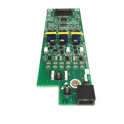
•BE116510 IP7WW-3COIDB-C11pc
•BE116502 IP7WW-SDVMS-C11pc
•BE117451 IP7WW-12TXH-B1 TEL(BK)(C)
4pcs
•A20-030439-001 INSTALLATIONCABLE:
MOD8-25PAIR 1pc
The SDVMS-
C1 equipped
with CPU-C1,
3COIDB-C1
equipped with
082U-B1 has
been initially
mounted into
the 4KSU-C1
chassis.
Also a Li bat-
tery has been
mounted on
the CPU with a
protection
sheet.
BE117450
SL2100 Digital Kit w/ 24B Tels
The Kit is Included;
•BE116491 IP7NA-4KSU-C1 1pc
•BE116496 IP7NA-CPU-C1 1pc
•BE116506 IP7WW-082U-B1 1pc
•BE116510 IP7WW-3COIDB-C11pc
•BE116502 IP7WW-SDVMS-C11pc
•BE117452 IP7WW-24TXH-B1 TEL(BK)(C)
4pcs
•A20-030439-001 INSTALLATIONCABLE:
MOD8-25PAIR 1pc
The SDVMS-
C1 equipped
with CPU-C1,
3COIDB-C1
equipped with
082U-B1 has
been initially
mounted into
the 4KSU-C1
chassis.
Also a Li bat-
tery has been
mounted on
the CPU with a
protection
sheet.
Q24-
FR00000013
6969
SL2100 IP QUICK START
KIT
Kit includes:
•BE116491 IP7NA-4KSU-C1 1pc
•BE116496 IP7NA-CPU-C1 1pc
•BE117453 IP7WW-8IPLD-C1 TEL (BK)(C)
4pc
•BE116745 SL2100 IP Trunk-01 LIC qty.2
•BE116751 SL2100 Email Notify LIC qty.1
•BE116746 SL2100 IP EXT-01 LIC qty.1
Included Licen-
ses are pre-
loaded onto
CPU.
CPU pre-instal-
led into KSU
Chassis
BE116491
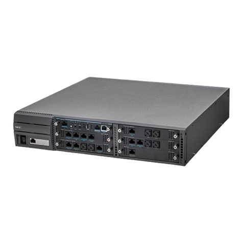
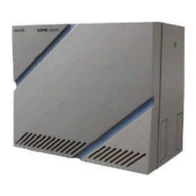
IP7NA-4KSU-C1
Main/Expansion Chassis with AC Cable (US
type)
•Power Supply with Backup Battery Circuit
•CPU/EXIFE Slot : 1, Universal Slot : 4

Other manuals for UNIVERGE SL2100

29

Other NEC Conference System manuals

NEC Conference Max Plus User manual

NEC

NEC Conference Max Plus User manual

NEC SV8500 User manual

NEC

NEC SV8500 User manual

NEC TOPAZ User manual

NEC

NEC TOPAZ User manual

NEC UNIVERGE SL2100 User manual

NEC

NEC UNIVERGE SL2100 User manual

NEC VisuaLink 384 User manual

NEC

NEC VisuaLink 384 User manual

NEC Univerge SV8100 User manual

NEC

NEC Univerge SV8100 User manual

NEC UNIVERGE UM8700 User manual

NEC

NEC UNIVERGE UM8700 User manual

NEC UNIVERGE SL2100 User manual

NEC

NEC UNIVERGE SL2100 User manual

NEC UNIVERGE SL2100 User manual

NEC

NEC UNIVERGE SL2100 User manual

NEC Univerge SV8100 User guide

NEC

NEC Univerge SV8100 User guide

NEC Aspila Topaz Owner's manual

NEC

NEC Aspila Topaz Owner's manual

NEC SOPHO 2000 IPS DM User manual

NEC

NEC SOPHO 2000 IPS DM User manual

NEC Univerge UM8000 User manual

NEC

NEC Univerge UM8000 User manual

NEC ASPILA EX Owner's manual

NEC

NEC ASPILA EX Owner's manual

NEC ElectraElite IPK Operating and installation instructions

NEC

NEC ElectraElite IPK Operating and installation instructions

NEC Univerge SV9100 Owner's manual

NEC

NEC Univerge SV9100 Owner's manual

NEC Univerge SV9100 User manual

NEC

NEC Univerge SV9100 User manual

NEC Univerge SV9100 User manual

NEC

NEC Univerge SV9100 User manual

NEC SL1100 User manual

NEC

NEC SL1100 User manual

NEC Univerge SV8100 User manual

NEC

NEC Univerge SV8100 User manual

NEC Aspire User manual

NEC

NEC Aspire User manual

NEC i-Series User manual

NEC

NEC i-Series User manual

NEC Univerge SV8100 Service manual

NEC

NEC Univerge SV8100 Service manual

NEC Univerge SV9100 User manual

NEC

NEC Univerge SV9100 User manual

Popular Conference System manuals by other brands

MARS COMMERCE GSW2 PLUS installation manual

MARS COMMERCE

MARS COMMERCE GSW2 PLUS installation manual

Panasonic KX-VC1600 user manual

Panasonic

Panasonic KX-VC1600 user manual

Polycom realpresence trio 8800 Features guide

Polycom

Polycom realpresence trio 8800 Features guide

Audio Technica ATUC-50 instruction manual

Audio Technica

Audio Technica ATUC-50 instruction manual

LifeSize Icon 600 installation guide

LifeSize

LifeSize Icon 600 installation guide

Polycom HDX Desktop Systems user guide

Polycom

Polycom HDX Desktop Systems user guide

Ascotel 2025 System manual

Ascotel

Ascotel 2025 System manual

Polycom RealPresence Group 300 user guide

Polycom

Polycom RealPresence Group 300 user guide

Graco 24N978 Instructions - parts

Graco

Graco 24N978 Instructions - parts

Clear One COLLABORATE VERSA 50 quick start guide

Clear One

Clear One COLLABORATE VERSA 50 quick start guide

Clear One ClearOne RAV 600 user manual

Clear One

Clear One ClearOne RAV 600 user manual

Clear One VERSA PRO CT quick start guide

Clear One

Clear One VERSA PRO CT quick start guide

PTZOptics PT30X-NDI-GY user manual

PTZOptics

PTZOptics PT30X-NDI-GY user manual

Clear One ClearOne RAV 600 Brochure & specs

Clear One

Clear One ClearOne RAV 600 Brochure & specs

Tripp Lite N252-024-HU-SHK installation guide

Tripp Lite

Tripp Lite N252-024-HU-SHK installation guide

Clear One Converge 560 datasheet

Clear One

Clear One Converge 560 datasheet

Redline RDL-3000 Series user manual

Redline

Redline RDL-3000 Series user manual

Clear One Converge Pro TH20 Installation and operation manual

Clear One

Clear One Converge Pro TH20 Installation and operation manual

manuals.online logo
manuals.online logoBrands
  • About & Mission
  • Contact us
  • Privacy Policy
  • Terms and Conditions

Copyright 2025 Manuals.Online. All Rights Reserved.