ISSUED: 11-16-05 SHEET #: 055-9447-2
Visit the Peerless Web Site at www.peerlessmounts.com 8 of 8 For customer service call 1-800-729-0307 or 708-865-8870.
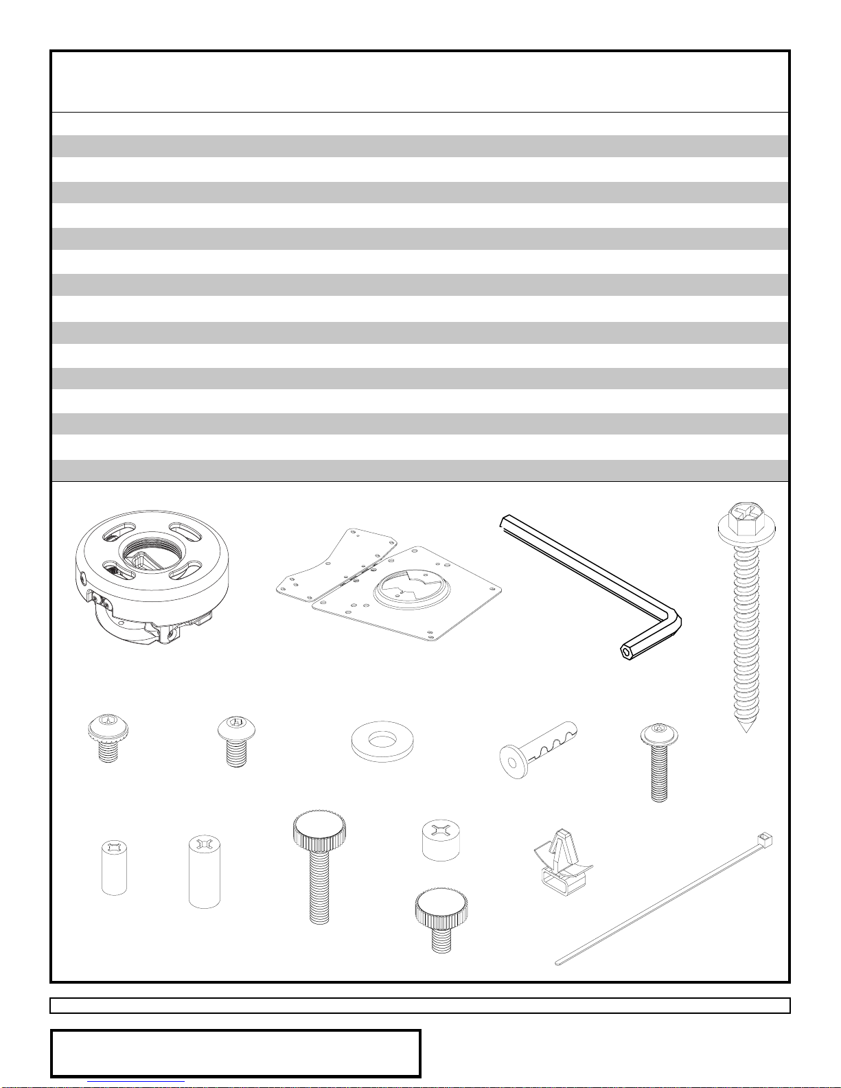
Accessories listed in the included sheet, as well as other parts,
can be ordered through Peerless by calling 1-800-729-0307 or
visiting www.peerlessindustries.com.
©2004PeerlessIndustries,Inc.Allrightsreserved.
PeerlessisaregisteredtrademarkofPeerlessIndustries.
Allotherbrandandproductnamesaretrademarksorregisteredtrademarksoftheirrespectiveowners.
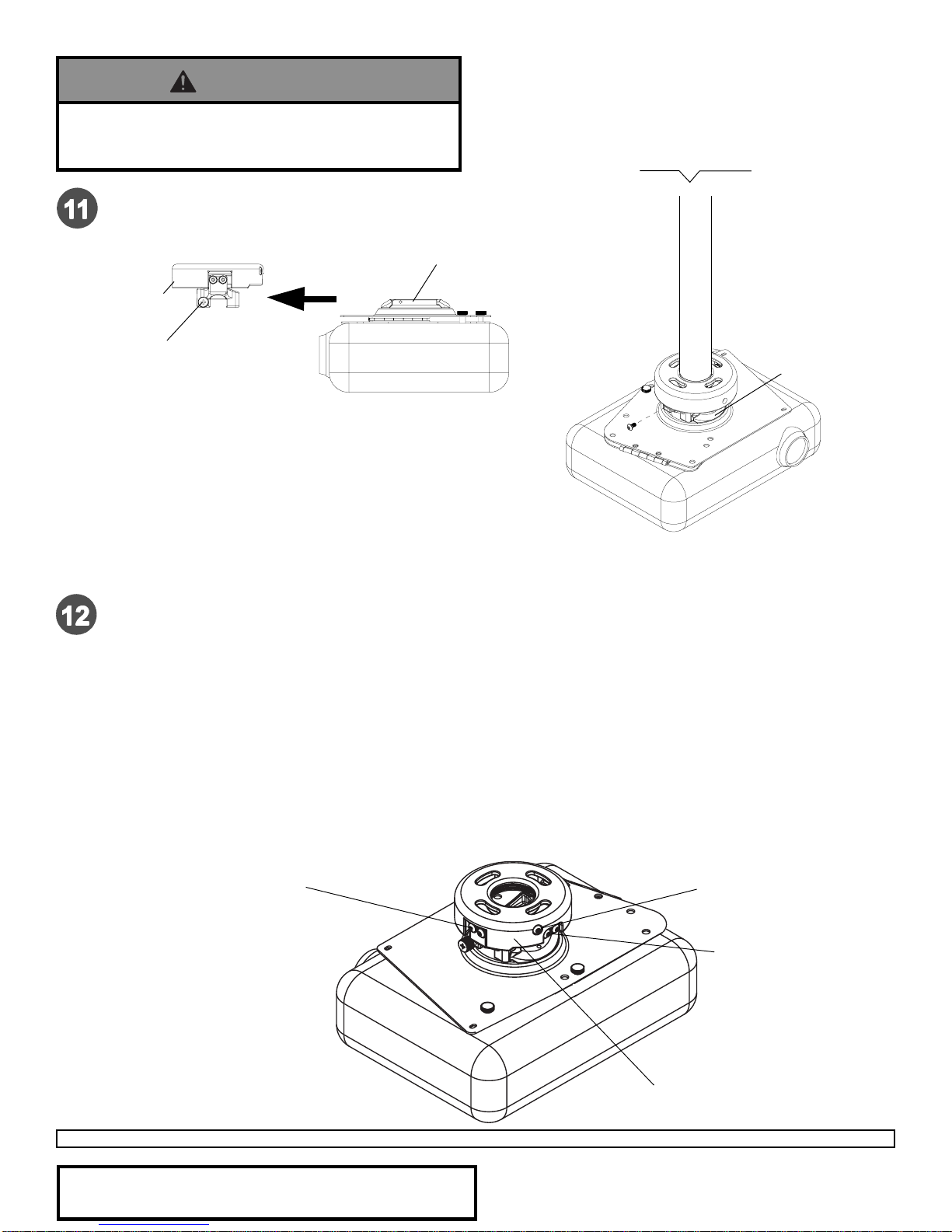
To adjust yaw (swivel) for wood stud, concrete ceiling, and threaded rod mounting applications:
Loosen wood screws (F), or locknuts for threaded rods, until projector mount can be rotated. Rotate mount to
desired position and retighten screws or locknuts.
To adjust yaw (swivel) for extension column applications: Loosen screw on projector mount assembly (A)
indicatedbelow until projector mount can be rotated. Rotatemount to desiredposition and retightenscrew.
To adjust pitch (forward and backward tilt): Loosen two screws on projector mount assembly (A) indicated
below. Tilt mount to desired position and retighten screws.
To adjust roll (side to side tilt): Loosen two screws on projector mount assembly (A) indicated below.Tilt
mountto desired positionand retighten screws.
Projector AlignmentProjector Alignment
Projector AlignmentProjector Alignment
Projector Alignment
SCREWFORSWIVELSTOP
A
SCREWSFORROLL
ADJUSTMENT
SCREWSFORPITCH
ADJUSTMENT
BACKOFMOUNT
Slideconnection block with projector intoprojector mount
assembly(A) as shown. Tightencaptive screw to secure
projectorto projector mount assembly(A).
IMPORTANT: For security installations, insert
one #10-32 x 1/4" socket pin screw (D) through
projectormount assembly (A)and into connection
block as shown.
ACONNECTIONBLOCK
D
CONNECTIONBLOCK
A
CAPTIVESCREW
FRONTOFMOUNT
• Do not lift more weight than you can handle. Use
additionalmanpoweror mechanical lifting equipment
tosafely handle placement oftheprojector.
WARNING