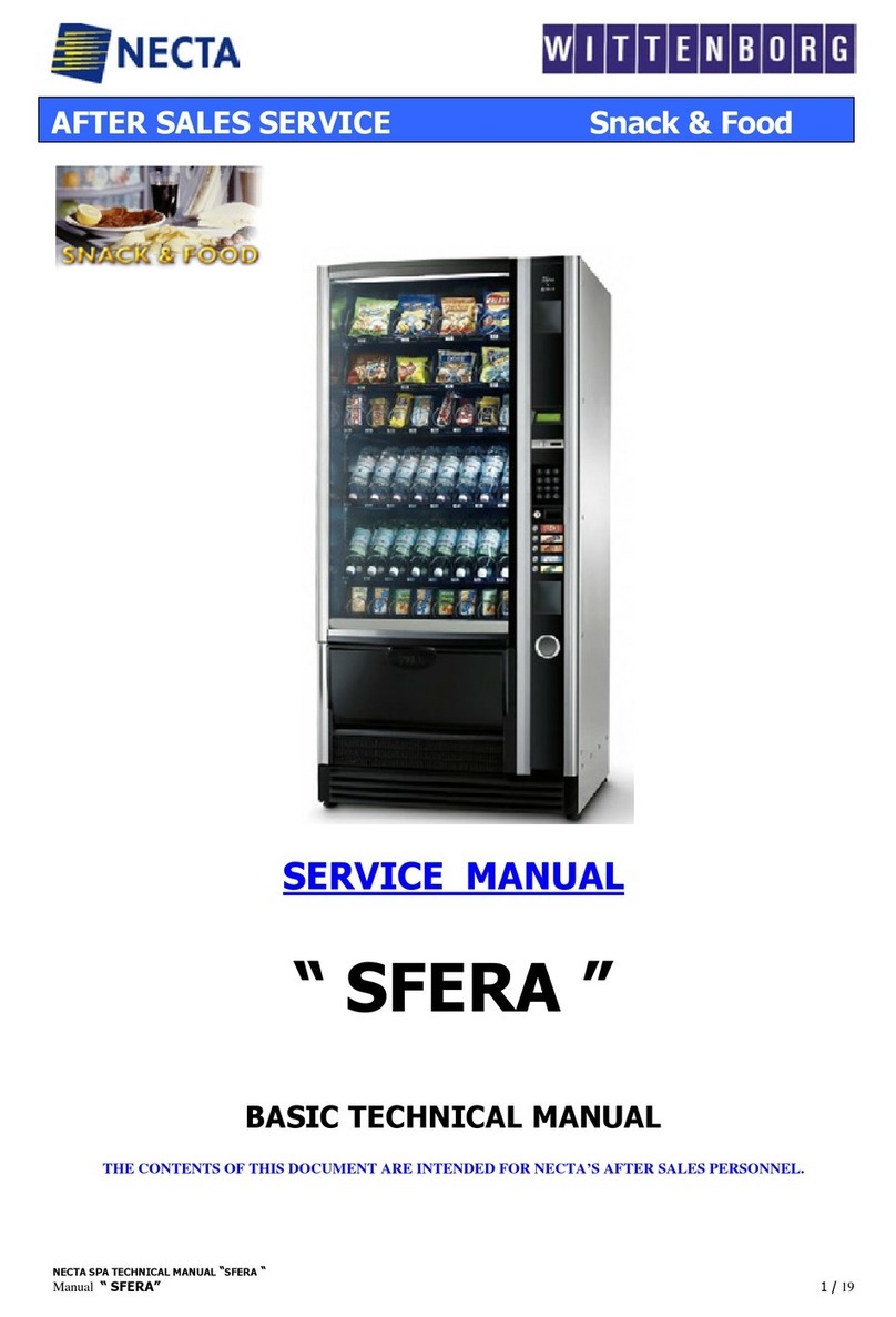
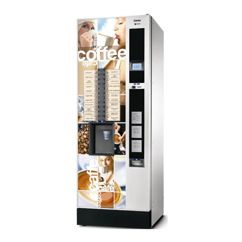
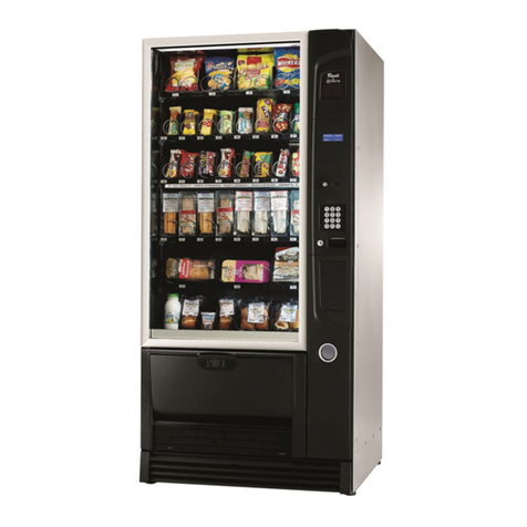
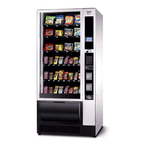
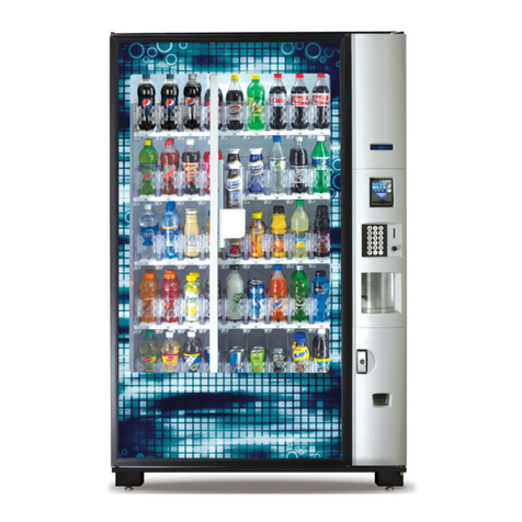
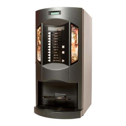
Necta SINFONIA GF6 Operating instructions

USER AND MAINTENANCE MANUAL
VENDING MACHINE
Mod. SINFONIA
Code : H4345 EN 00
Date: February 2013

Instructions
for Installer,
Maintenance Engineer
and final User
SINFONIA
Rev. 00
H4345 - 00 02/2013 Page 2 of 41
INDEX
1 GENERAL INFORMATION...............................................................................................................................3
1.1 Purpose of Manual......................................................................................................................................... 3
1.2 Interested people ........................................................................................................................................... 3
1.3 Responsibility ................................................................................................................................................. 3
1.4 Manufacturer .................................................................................................................................................. 3
1.5 Service Centres ............................................................................................................................................. 3
1.6 Warranty ........................................................................................................................................................ 4
1.7 General safety warnings ................................................................................................................................ 4
1.8 Symbols ......................................................................................................................................................... 5
2 MACHINE FEATURES......................................................................................................................................6
2.1 Technical Features ........................................................................................................................................ 6
2.2 Description of Components ........................................................................................................................... 7
3 INSTALLATION ...............................................................................................................................................8
3.1 Transport and Positionning ............................................................................................................................ 8
3.2 Characteristics of Installation Area ................................................................................................................ 9
3.3 Removing of Wooden Bases ......................................................................................................................... 9
3.4 Levelling ......................................................................................................................................................... 9
3.5 Stability ........................................................................................................................................................ 10
3.6 Connection to Power Mains ......................................................................................................................... 11
3.7 Coin Mechanism Installation ........................................................................................................................ 12
3.8 Control Settings ........................................................................................................................................... 13
4 ACCESS TO INTERNAL PARTS ...................................................................................................................13
5 USING THE VENDING MACHINE..................................................................................................................14
5.1 Warnings ...................................................................................................................................................... 14
5.2 Proper Use ................................................................................................................................................... 14
5.3 Loading Products ......................................................................................................................................... 15
5.4 Loading Operation ....................................................................................................................................... 16
5.5 Extraction of shelves.................................................................................................................................... 18
5.6 Final Check .................................................................................................................................................. 20
5.7 Control Setting ............................................................................................................................................. 20
5.8 Start-up ........................................................................................................................................................ 20
5.9 Replacement of TRAY (SHELF) ASSY height Instruction ........................................................................... 21
6. Description and function of control unit....................................................................................................24
6.1 Display ......................................................................................................................................................... 24
6.2 Key board .................................................................................................................................................... 25
6.3 Set the temperature ..................................................................................................................................... 25
6.4 Quick defrost ................................................................................................................................................ 25
6.5 Description of the main signals and alarms ................................................................................................. 26
6.6 Function ....................................................................................................................................................... 26
7 MAINTENANCE .............................................................................................................................................27
7.1 Access to Maintenance Area ....................................................................................................................... 27
7.2 Preventive Maintenance .............................................................................................................................. 27
7.3 Removing and Installing the Bucket ............................................................................................................ 28
7.4 Led Tube Replacement ............................................................................................................................... 29
7.5 Drum Photocell Adjustment ......................................................................................................................... 30
7.6 Cleaning of the Vending Machine ................................................................................................................ 31
7.7 Warnings ...................................................................................................................................................... 31
7.8 General Cleaning Operation ........................................................................................................................ 32
7.9 Recommended Cleaning Products .............................................................................................................. 33
7.10 Safety device for cleaning ......................................................................................................................... 33
8 INFORMATION – DANGER SIGNS ..............................................................................................................34
9 TROUBLESHOOTING GUIDE.......................................................................................................................36
10 STORAGE AND CLEARANCE ...................................................................................................................38
10.1 Storage ...................................................................................................................................................... 38
10.2 Clearance (disposal) .................................................................................................................................. 38
10.3 Person in Charge of Disposal .................................................................................................................... 39
10.4 Sanctions ................................................................................................................................................... 39

Instructions
for Installer,
Maintenance Engineer
and final User
SINFONIA
Rev. 00
H4345 - 00 02/2013 Page 3 of 41
1 GENERAL INFORMATION
1.1 Purpose of Manual
The manual contains the correct procedures for loading, usage, regular and extra-ordinary maintenance and
installation of vending machines. This manual is a very important part of the vendor and therefore must be
kept intact and available for the whole productive life of the vendor .
KEEP INSIDE THE MACHINE
1.2 Interested people
This manual is for the persons in charge of loading, cleaning and ordinary maintenance of the machine.
(Loading Operator), the final user (User)) and the people involved in installing, setting, extraordinary
maintenance of the vendor (Installer/Maintenance Technician). The persons in charge must know the
instructions and comply with the procedure of the manual.
Technicians allowed to operate one this vending machines
Operator (person who only loads the machine with products to be sold)
o The operator can only load products to be sold in the vending machine.
o Doing this operation the operator should never move the protective lower carter as indicated
on the related safety icon-label on the protection.
Maintenance Engineer / Skilled technician
o In order to perform all the operations requiring to dismount the protective lower carte, it is
necessary to contact only SandenVendo technicians or only authorized (by SandenVendo)
skilled and prepared technicians due to the potential electrical and mechanical risks.
The appliance is not to be used by children or persons with reduced physical, sensory or mental capabilities,
or lack of experience and knowledge, unless they have been given supervision or instruction. Children being
supervised not to play with the appliance. Instructions state that access to the service area is restricted to
persons having safety/hygiene knowledge and practical experience of the appliance (IEC 60335-2-75).
1.3 Responsibility
The responsibility of the manufacturer is limited to the correct usage of the vendor
“SandenVendo Europe S.p.A” declines any responsibility for possible damages caused to people and/or
things as a result of:
- Incorrect installation.
- Usage of unoriginal spare parts.
- Unforeseen modifications/authorized by manufacturer.
- Improper use of vendor
- Connection to inadeguate supply system and not in conformity with the regulations in force
1.4 Manufacturer
“SandenVendo Europe S.p.A.” claims more than 20 years of experience in the manufacturing of Vending
machines, and it is the technical know-how acquired, after years of researches and close contact with the
production and commercialisation at global level that represents the best warranty SandenVendo Europe
S.p.A. can offer
SandenVendo Europe S.p.A.
SandenVendo Europe S.p.A.SandenVendo Europe S.p.A.
SandenVendo Europe S.p.A.
Strada Statale Casale Torino km 4
15030 Coniolo (AL) - ITALIA
Tel.: +39 0142 335111 – Fax: +39 0142 562348
e-mail: infosve@sandenvendo.com
website: www.sandenvendo.com
1.5 Service Centres
N&W GLOBAL VENDING S. p. A.
Via Roma 24
24030 Valbrembo
Italy - Tel. +39 035606111

Instructions
for Installer,
Maintenance Engineer
and final User
SINFONIA
Rev. 00
H4345 - 00 02/2013 Page 4 of 41
1.6 Warranty
The warranty of the vending machine components, starting from the date shown on the delivery note, is 24
months for the cooling unit.
The warranty covers exclusively replaced parts, with labour excluded.
The warranty does not include, damages to the vendor caused by:
• Transport and/or handling
• Operator errors
• Lack of maintenance contemplated for in this Manual
• Failures and/or breakages not caused by the malfunction of the vending machine
1.7 General safety warnings
Carefully read the manual before starting or loading the vendor
Protect the vendor against weather conditions
Do not remove the protection cover unless you are a maintenance technician
Do not change the setting of the electronic board before reading this manual
Do not place the vendor under direct sunlight
Do not sell products with the door open
Refer to routine maintenance chapter for cleaning the vendor
Disconnect the power cable before doing assistance or freeing a jammed product
Use a special protection system
The vendor must be installed in a way that the electric plug is accessible after installation
If the power cable is damaged, it should be substituted by the manufacturer or by his after-sales
technicians or however by an equally qualified person, in order to avoid any risks
The vendor should not be installed in an area where water jets are used
The vendor should not be installed outdoor
To preventy hazards due to machine instability,secure the machine according to the instructions
In case of failure and/or poor operation, please contact exclusively the qualified personnel of our
service centres
Use only spare parts authorised by the manufacturer
Should this manual be lost or damages, you may ask for a copu from the manufacturer, enclose the
serial number of your vending machine with youur request
CAUTION: FAILURE TO ABIDE BY THE INSTRUCTIONS CONTAINED IN THIS MANUAL MAY
INVOLVE DAMAGES TO THE VENDOR AND/OR PERSONNEL
The pictures and illustrations in this document are only indicative. SandenVendo
Europe S.p.A. recalls that the technical and performance of products can
change without notice.
“SandenVendo Europe S.p.A.”. reserves the right of making changes on their
vending machines without any advice; moreover they declare that the vendors
listed in this manual are in conformity with the following directives: 98/37/CE (EC
markings).

Instructions
for Installer,
Maintenance Engineer
and final User
SINFONIA
Rev. 00
H4345 - 00 02/2013 Page 5 of 41
1.8 Symbols
In the manual and/or on the vendor, warning areas have been indicated with signs, plates, symbols
oricons showing danger or obligations in each case
The symbols used in the manual and on the vendor are the following:
SIMBOL
MEANING
COMMENT
Compulsory Compulsory for personnel involved
Compulsory Compulsory for personnel involved to wear protective
gloves during maintenance on the vendor
Compulsory Compulsory for personnel involved to wear protective
clothes during maintenance
i
Extra information Additional information is given
Manual Before doing indicated operation, refer to the instructions in
the Manual
Maintenance
operations
In case of a particular function and/or irregularity, a
mechanical adjustment and/or electric setting could be
required.
Warning Indicates a warning, failure to comply may involve damages
to the vending machine
Danger Extreme care must be given when operating the vend
mechanism
Danger Extreme care must be given when using electric cables
Danger Indicates information concerning personnel safety and
machine’s integrity
Danger/Forbidden
Indicates a danger of electric shock and mechanical risk.
It is forbidden to remove this safety guard.
Only SandenVendo Europe technicians or authorized
personnel can open this safety guard
Clearance Clear in conformity with the recycling procedures
Recycling The recycling of this product helps to reduce the need of
new material and piling up of waste.

Instructions
for Installer,
Maintenance Engineer
and final User
SINFONIA
Rev. 00
H4345 - 00 02/2013 Page 6 of 41
2 MACHINE FEATURES
2.1 Technical Features
MOD. GF6-DR6
Dimensions
GF6 DR6
Height (A) with feet 1830mm 1895mm
Height (A) with leveling screws 1765mm 1830mm
Width (C) 950mm
Depth (B) STD door / Flat door 860 / 845 mm
Weight 290kg 297kg
Electric features
Nominal tension 230 V
Nominal frequency 50 Hz
Installed electric power 850W
Cooling unit
Compressor (12.11CC) cm³
Refr. Power 1058W
Working range 18 ÷ 32°C 65% R.H.
Settable temperature range 1°C
÷ 25°C
Refrigerant R404A
Load 0,360 Kg
Expansion direct with capillary
Cooling forced circulation by means 3 fans
FIG. 2.1
MOD. GF9-DR9
Dimensions
GF9 DR9
Height (A) with feet 1830mm 1895mm
Height (A) with leveling screws 1765mm 1830mm
Width (C) 1220mm
Depth (B) STD door / Flat door 860 / 845 mm
Weight 340 kg 350 kg
Electric features
Nominal tension 230 V
Nominal frequence 50 Hz
Installed electric power 850W
Cooling unit
Compressor (12.11CC) cm³
Refr. Power 1058W
Working range 18 ÷ 32°C 65% R.H.
Settable temperature range 1°C
÷ 25°C
Refrigerant R404A
Load 0,360 Kg
Expansion direct with capillary
Cooling forced circulation by means 3 fans
Subject to technical changes!
FIG. 2.2
B
C
A
A
B
C

Instructions
for Installer,
Maintenance Engineer
and final User
SINFONIA
Rev. 00
H4345 - 00 02/2013 Page 7 of 41
1
SHELVES
2 LED
3 DOOR LIFT WHEEL
4 LEVELLING SCREW
5 COOLING UNIT
6 CONTROL PANEL
FIG. 2.4
2.2 Description of Components
FIG. 2.3
1
CBV PLUG COVER
2 DISPLAY
3 COIN INTRODUCTION
4 PUSH BUTTONS
5 PRODUCT EYELET
6 DOOR LOCK
7 COIN RETURN
8 PRODUCTS WINDOW
9 LOWER DOOR PANEL
10 DOOR UPPER DECOR
11 DOOR LOWER DECOR
1
2
3
4
5
6
7
10
9
8
1
2
6
5
4
3

Instructions
for Installer,
Maintenance Engineer
and final User
SINFONIA
Rev. 00
H4345 - 00 02/2013 Page 8 of 41
3 INSTALLATION
3.1 Transport and Positionning
FIG. 3.1
MODEL
A
(mm)
B
(mm)
C
(mm)
WEIGHT
(Kg)
GF6-DR6 1830
860
(845)
950 290
GF9-DR9 1830
860
(845)
1220
340
GF6-DR6 packed 1830
880 960 295
GF9-DR9 packed 1830
880 1230
345
For transport and HANDLING of the vendor follow carefully the below instructions:
• Use a transpallet/forklift having a minimun loading capacity of 400 kg., the wooden base (A) permits
to fork the vendor on 4 sides (fig. 3.1).
• If installation is not immediate position the vendor vertically in a dry and covered area.
• CAUTION: it is absolutely forbidden to transport and/or position the vendor in a horizontal position.
• If the machine is mistakenly placed in a horizontal position, re-position it again in working
position (vertical) and wait at least12 hours before starting it, otherwise it would be possible to
cause damages or anomalies to the cooling unit.
• Place the vendor in the installation area, work with caution, avoid jumps and bumps.
• Free the machine from its packing, extract, from the back protection grill, the power cable and
carefully place it in the final position.
A
A
A
B
C

Instructions
for Installer,
Maintenance Engineer
and final User
SINFONIA
Rev. 00
H4345 - 00 02/2013 Page 9 of 41
3.2 Characteristics of Installation Area
CAUTION: THE MACHINE IS NOT SUITABLE FOR OUTDOOR INSTALLATION
CAUTION: DO NOT USE JETS OF WATER TO CLEAN VENDOR, DO NOT PLACE THE
VENDOR IN AREAS WHERE JETS OF WATER ARE USED
Environmental conditions for installing vendor
• “Mod. GF6-GF9-DR6-DR9” vendors must be installed in an area/room where temperature does not
exceed 32 °C or fall below 10 °C, otherwise the ele ctric parts (compressor) could overheat or
malfunction.
• The air circulation is very important for the cooling unit, check that there is a 10 cm gap between the
rear of the vendor and the obstacle (wall).
• Check that the surface where the vendor is placed supports the weight of the machine.
3.3 Removing of Wooden Bases
To remove wooden bases, work as follows:
• With a transpallet lift the machine from the floor (holding it from the Front)
• With an adjustable wrench unscrew the screws that fasten the wooden base to the machine: 2
screws on the right hand side and 2 screws on the left hand side
• Assemble the 4 feet on the base of the machine
• Place the machine on the floor
3.4 Levelling
In order to have the best working conditions place the vendor on a perfectly levelled surface. Any
irregularities on the floor can be compensate by adjusting the screw-on feet on the vending machine to
obtain a perfect levelling and guarantee stability.
i
THE BEST PERFORMANCE IS GUARANTEED IF THE VENDOR IS PLACED ON A HORIZONTAL
SURFACE

Instructions
for Installer,
Maintenance Engineer
and final User
SINFONIA
Rev. 00
H4345 - 00 02/2013 Page 10 of 41
3.5 Stability
The stability of the SandenVendo vending machine is granted whether the vending machine empty or full
and / or with the door open.
The overturning of vending machine without external influences is quite impossible.
Against the vandalism, such as possibility of tilting the Vending machine, the following optional kits are
applicable to meet your needs.
1) Wall fixing kit P/N 135078/2
Components provided:
2 x Welded rear bracket A P/N 130461/1
2 x Bracket B P/N 386460
2 x Plugs with screw P/N 391598
12 x Screw P/N 390139
2) Ground anchor kit P/N 139218
Components provided:
4 x Bracket fixed to the ground P/N 402852
16 x Thick metals P/N 402854
12 x Screw 6,3 x 19 P/N 800876
ATTENTION:
SandenVendo does not assume responsibi
lity for any damage caused by the
lack of consultation of the instructions. All the operations must be done by
authorized personnel.
A
B
Use the suitable
material to secure
fixing the Vending
machine to the floor.
12 Hole
Ø 5.5mm
After making 12 holes Ø5mm tighten
the 4 brackets provided on the
cabinet base keeping an appropriate
distance from each other.
For adjust differences in
level, use the thick metals
provided.

Instructions
for Installer,
Maintenance Engineer
and final User
SINFONIA
Rev. 00
H4345 - 00 02/2013 Page 11 of 41
3.6 Connection to Power Mains
SERVICE CORD INSTALLATION
It is obligatory the use of a switch, in conformity to installation regulations, placed in an accessible position,
which has characteristics suitable to withstand the maximum load required and ensure complete
disconnection from the network under the conditions of overvoltage category III and thus ensuring the
protection of circuits against earth faults, overloads and short circuits.
CAUTION: BEFORE DOING ELECTRICL CONNECTION CHECK THE FOLLOWING :
Assure that the characteristics of the poer supply (voltage and frequency) correspond to those
indicated on the plate with technical details of the machine: this vendor must be connected to a
230 V, 50 Hz. power main, voltage under 207 V or over 253 V could cause failures
Assure that, the supply outlet is grounded and that, after making connection the entire appliance
is ground connected.
Assure that the vendor is positioned in a way that the plug for connection to the power main is
accessible after installation
Assure that the neutral wire is blue, otherwise invert the poles
CAUTION
:
The power cord is the type with non
-
separable plug. The replacement of the
cable should only be performed by qualified personnel using only cable H05 RN - F or V
HO5 VF or H07 RN-F 3x1-1, 5 mm2 of sections.
CAUTION: DO NOT ABSOLUTELY USE EXTENSION CORDS
FIG.1
FIG.2
FIG.3
1) Unscrew the 2 screws in FIG.1
2) Pull out the service cord until the
fastening plate appears as in FIG.2
3) Fasten the plate with the 2 screws
as in FIG.3

Instructions
for Installer,
Maintenance Engineer
and final User
SINFONIA
Rev. 00
H4345 - 00 02/2013 Page 12 of 41
3.7 Coin Mechanism Installation
Hook the coin box on the 3 screws (E) located on the coin box door (F).
Check that the coin slot on the coin box is in line with the outlet of the coin channel (G) and that the distance
between the two parts is approx. 10 mm max.
The distance is adjustable loosening the 4 fastening screws (H) of the door and sliding it up or down. Once
finished remember to tighten the screws again.
FIG. 3.4
You can move it at a right angle by placing spacers (washer 1) between the coin box door and the back of
the coin box support .
When it is perfectly centered, remove the selector and tighten the 3 supporting screws (E).
Caution: these operations are not necessary using the coin mechanism recommended by SandenVendo
Europe S.p.A.
Press the coin return button and check that the mechanism works smoothly. It is important that the selector
opens as much as possible. If this doesn’t happen adjust again the height of the coin return motor.
Connect the coin mechanism to the MDB connector that is inserted on a support near the coin box.
i
THE COIN MECHANISMS WITH EXECUTIVE PROTOCOL HAVE 2 CONNECTORS; A POWER
SUPPLY CONNECTOR THAT COMES DIRECTLY FROM THE TRANSFORMER BOX, AND A
COMMUNICATION ONE FROM THE MAIN BOARD.
10mm
H
F
G
E

Instructions
for Installer,
Maintenance Engineer
and final User
SINFONIA
Rev. 00
H4345 - 00 02/2013 Page 13 of 41
3.8 Control Settings
All the control and operation settings of the machine are set through the programming routine of the SF01
electronic board.
The programming routine of the electronic board is described in the SF01 PROGRAMMING MANUAL
supplied with the vendor.
i REFER TO THE SF01 PROGRAMMING MANUAL
4 ACCESS TO INTERNAL PARTS
Access inside the machine (maintenance area) is possibile yusing the specially provided key supplied with
the vendor (rif. Fig. 4.1).
Access to the service area is possible only using a specially provided tool.
Hereunder is a list of the service areas of the vending machine :
• LED (lighting area)
• Refrigerant Unit
• Transformer box-board
FIG. 4.1
FIG. 4.1
TRANSF
ORMER BOX
-
BOARD
COIN MECHANISM
PRODUCT DELIVERY MECHANISM
COIN BOX

Instructions
for Installer,
Maintenance Engineer
and final User
SINFONIA
Rev. 00
H4345 - 00 02/2013 Page 14 of 41
5 USING THE VENDING MACHINE
5.1 Warnings
CAUTION: DO NOT LOAD THE VENDOR WITH PRODUCTS DIFFERENT FROM THE ONES
RECOMMENDED BY THE MANUFACTURER (REFER TO CHAPTER PROPER USE )
5.2 Proper Use
“Mod. GF6-GF9-DR6-DR9” vendors have been designed and built for vending and distributing the following
products:
Modell GF6 Modell DR6
Can capacity 0.33 (h.116)
336 (7 Shelf) 384 (8 Shelf)
Can 0.33 (h.146)
288 (6 Shelf) 336 (7 Shelf)
Bottle capacity 0.50 PET (h.210)
240 (5 Shelf) 240 (5 Shelf)
Bottles 0.50 Coca Cola (h.235)
192 (4 Shelf) 240 (5 Shelf)
Selling cycle time
Max. 13 sec.
No. shelves
from a minimum of 4 to a maximum of 7
Selections
standard 30/max.42
Modell GF9 Modell DR9
Can capacity 0.33 (h.116)
504 (7 Shelf) 576 (8 Shelf)
Can 0.33 (h.146)
432 (6 Shelf) 504 (7 Shelf)
Bottle capacity 0.
50 PET (h.210)
360 (5 Shelf) 360 (5 Shelf)
Bottles 0.50 Coca Cola (h.235)
288 (4 Shelf) 360 (5 Shelf)
Selling cycle time
Max. 13 sec.
No. shelves
from a minimum of 4 to a maximum of 7
Selections
standard 45/max.63
PRODUCTS SIZE:
PET bottles, Glass bottles, Cans
Diameter: min. 43,5mm – max. 71,5mm
Height: min. 88mm – max. 266mm
Weight: min. 185g – max. 653g
Carton packs (brick)
Width: min. 52mm – max. 67mm
Depth: min. 40mm – max.47mm
Height: min. 85mm – max. 134mm
Weight: min. 213g – max. 400g
Attention:Some products although within the above dimensions could
be difficult to load due to their shape.

Instructions
for Installer,
Maintenance Engineer
and final User
SINFONIA
Rev. 00
H4345 - 00 02/2013 Page 15 of 41
5.3 Loading Products
The products that can be delivered are loaded in each shelf inside the machine.
FIG. 5.1 – VENDING SYSTEM
For loading products inside the machine follow the instructions below:
- open the vending machine door (ref. 7.1 ACCESS TO THE MAINTENANCE AREA);
- pull out the shelf until it reaches the blocking point
- push back the pusher until it hooks the back bar of the shelf
- place the products in the selection in front of the pusher, until completely loaded
- push the shelf back to it’s working position, the pusher unhooks automatically
- Re-close the door of the vendor and wait for the reset check of the parameters configuration
Caution
: When the shelf is pushed back to its working position, the pusher unhooks
automatically and presses against the product.
If a selection is not loaded the pusher returns to the starting position in a “violent”
way because of the spring.
In order to avoid this condition unhook manually e accompany the pusher before
returning the shelf in it’s working position.
SHELF 1
SHELF 2
SHELF 3
SHELF 4
SHELF 5
SHELF 6
SHELF 7
SHELF 8

Instructions
for Installer,
Maintenance Engineer
and final User
SINFONIA
Rev. 00
H4345 - 00 02/2013 Page 16 of 41
5.4 Loading Operation
- Follow the below photos for loading products
It is absolutely forbidden to step on the lift during loading
It is absolutely forbidden to use the shelf as support
ALWAYS HOLD THE PUSHER OF AN EMPTY
SELECTION AFTER UNHOOKING IT

Instructions
for Installer,
Maintenance Engineer
and final User
SINFONIA
Rev. 00
H4345 - 00 02/2013 Page 17 of 41
- Pull out the shelf until it reaches the blocking point
- Push the pusher back until it is hooked to the back bar of the shelf
PRODUCT PUSHER
PUSHER SPRING
PUSHER HOOKED TO SHELF’S
BACK BAR

Instructions
for Installer,
Maintenance Engineer
and final User
SINFONIA
Rev. 00
H4345 - 00 02/2013 Page 18 of 41
- Load products in the space in front of the pusher and replace the shelf in its working position
5.5 Extraction of shelves
To extract shelves do the following:
- Place the palm of your hand under the shelf and lift it slighty to allow unhooking
SHELF BRACKET

Instructions
for Installer,
Maintenance Engineer
and final User
SINFONIA
Rev. 00
H4345 - 00 02/2013 Page 19 of 41
Follow below procedures for extracting only the first shelf on the bottom left side :
1) Manually open the vend door
2) The product bucket moves from left to right allowing extraction of the shelf
3) Extract the shelf lifting it slightly
4) The procedure for product loading is the same as the other shelfs
When closing the door, the bucket returns to starting position
BUCKET MOVING FROM LEFT TO RIGHT
VEND DOOR
LIFT SHELF FOR EXTRACTING
WHEN CLOSING THE DOOR THE PRODUCT
RETURNS TO STARTING POSITION
PRODUCT CATCHING
BUCKET

Instructions
for Installer,
Maintenance Engineer
and final User
SINFONIA
Rev. 00
H4345 - 00 02/2013 Page 20 of 41
5.6 Final Check
1- Load the shelves completely
2- Do several selections, check product delivery
It is possible to send your products to the factory, tests will done for correct adjustment.
USUAL PRODUCTS ARE NORMALLY TESTED IN THE FACTORY, ASK FOR THE SETTING
NUMBER OF THE PRODUCT THAT YOU WISH TO SELL AND REFER TO THIS NUMBER WHEN
ORDERING. WE WILL PRODUCE THE VENDOR ACCORDING TO YOUR SPECIFICATIONS.
5.7 Control Setting
All the machine’s contro ald operation settings can be set through the programming routine of the SF01
electronic board.
The programming routine of the electronic board is described in the SF01 PROGRAMMING MANUAL
supplied with the vending machine
i
REFER TO SF01 PROGRAMMING MANUAL
5.8 Start-up
To start-up the Vending machine, work as follows:
• Assure that the plug is connected to the supply mains.
• Give power to the Vendor: ppress the luminous green button MAIN SWITCH situated on the
transformer box inside of the machine (on the sliding panel next to the cell).
• The led tubes switch on through the MAIN SWITCH placed on the front part of the transformer box.
• Execute the programming routine: refer to SF01 Programming Manual
• Load the vendor with the desired products
• Close the vendor door and wait for the general machine check
• The vendor is now ready for vending.
CAUTIONS: IN CASE OF FAILURE AND/OR BAD PERFORMANCE OF THE MACHINE, CONTACT
ONLY THE QUALIFIED PERSONNEL AT OUR SERVICE CENTER
This manual suits for next models
3
Table of contents
Other Necta Vending Machine manuals

Necta
Necta Zenith Fresh Brew Instant Installation guide

Necta
Necta Rondo Owner's manual

Necta
Necta Astro User manual

Necta
Necta StarFood Installation guide

Necta
Necta Snakky 6-30R/I User manual

Necta
Necta Sfera 6-36 R/F User manual

Necta
Necta Samba Top Owner's manual

Necta
Necta Snakky Service manual

Necta
Necta Colibri Manual

Necta
Necta Snakky User manual
Popular Vending Machine manuals by other brands

Westomatic
Westomatic Primo Compact Cleaning manual

Crane Merchandising Systems
Crane Merchandising Systems VOCE Media Operator's manual

Kubota
Kubota GF-41S Operation manual

Westomatic
Westomatic Sigma Touch Operator's & installation manual

Newtech
Newtech Flovend 1 manual

Godrej
Godrej Minifresh 2000 user manual